That is a VERY interesting reason. Let me check the board with care, and be back to you with the details. Also, about the diodes I want to know your suggested position of these.
That is a VERY interesting reason. Let me check the board with care, and be back to you with the details. Also, about the diodes I want to know your suggested position of these.
Ок.
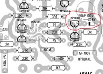
The correct position of the diodes and zener diodes I signed red "correct"
P.S. I redrawed your attachments in a graphical application correctly and laid out in my posts.
Last edited:
Hennady he is the thing: attached is the original board component distribution. the Wilson Mirror transistor is inverted. Anyway I could assemble with the transistor in the typical position as you kindly suggest.
It would be nice to know what test method could be efficient to tell the difference using the simulator ...
It would be nice to know what test method could be efficient to tell the difference using the simulator ...
Attachments
On the board the transistor is drawn incorrectly, it is necessary to swap the Сollector and the EmitterHennady he is the thing: attached is the original board component distribution. the Wilson Mirror transistor is inverted. Anyway I could assemble with the transistor in the typical position as you kindly suggest..
Measure the voltage across resistor R11 (3k) in the emitter T5....It would be nice to know what test method could be efficient to tell the difference using the simulator ...
This voltage should be equal to the voltage at zener D1 (6V)
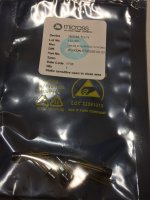
I think you owe me an apology. I am just trying to help GM builders and buy genuine parts.
I'm sorry and thanks your try to diy community.
I busyness for answer before via email.
I will soon arrange to order a few to build GM 2017.
Tks u,
Now, do you still think I offer fake parts?
Attachments

Why don't you try two bipolar capacitor in series for the NFB electrolytic?
That cap combo ranked the best, less THD option, in Cyril Bateman's capacitor testing articles.
That cap combo ranked the best, less THD option, in Cyril Bateman's capacitor testing articles.
Why don't you try two bipolar capacitor in series for the NFB electrolytic?
That cap combo ranked the best, less THD option, in Cyril Bateman's capacitor testing articles.
Because I am publishing a "reference" schematic.😉
Why don't you try two bipolar capacitor in series for the NFB electrolytic?
That cap combo ranked the best, less THD option, in Cyril Bateman's capacitor testing articles.
Carlos,
Can you send the link for this work?
I normally use 2 polarized electrolytic connected in reverse to simulate a non-polar one. This way is used in some Krell amplifiers and works very well with a good low frequency behaviors.
Tks in advance.
Because I am publishing a "reference" schematic.😉
... Which could innovate on using a better type of parts, 😉
You really should use non-polarised in there as there is AC cross that cap, not DC. Polarised caps don't play well with reverse current. Non-polarised is the tool for the job.
The feedback position is probably the most critical for sound quality in the entire amplifier and the components there make more difference than anywhere else. If you can only afford one Vishay Z foil, that's the place for it (though they are only 0.4Watts, I've previously paralleled two Vishays bulk foils for there), and if you really must have DC blocking there then use the very best sounding cap you can get, I used to use Black Gate Nx, but it does sound better with no cap (and risk some DC gain).
There is the Nichicon Muse NP, they might be smooth foil, not etched. Also some MLCC of reasonable size might be worth a try to hear what they sound like.
UES1C471MHM Nichicon | Mouser United Kingdom
http://www.mouser.com/ds/2/293/e-ues-876267.pdf
Last edited:
You really should use non-polarised in there as there is AC cross that cap, not DC. Polarised caps don't play well with reverse current. Non-polarised is the tool for the job.
The feedback position is probably the most critical for sound quality in the entire amplifier and the components there make more difference than anywhere else. If you can only afford one Vishay Z foil, that's the place for it (though they are only 0.4Watts, I've previously paralleled two Vishays bulk foils for there), and if you really must have DC blocking there then use the very best sounding cap you can get, I used to use Black Gate Nx, but it does sound better with no cap (and risk some DC gain).
There is the Nichicon Muse NP, they might be smooth foil, not etched. Also some MLCC of reasonable size might be worth a try to hear what they sound like.
You mean, this way?
Then, why genuine GM uses polarized caps in parallel?
Attachments

No, just one non-polarised cap between the resistor and earth.
A NP cap is equivalent to the two caps in the above drawing. Except it has in the signal path less copper track, solder joints, leads, joins, electrolyte, foils, distortion, therefore can sound better or a lot better.
Manufacturers usually do things like this for cost saving. Two of the cheapest polarised caps they can source vs. a expensive audio grade NP, and maybe the manufacturer is supplied by a company that doesn't make an NP electrolytic. We can only guess at the political and economic machinations behind the component choices.
The best thing is to try different makes, sizes and type of caps there for yourself, run them in, listen to them, then make an educated decision. That's what I've done, and for me the best no cap, DC coupled 🙂
Edit: Parallel caps will have lower ESR and maybe better, or different, bass response. Maybe they were EQ'ing their amplifier. In the Hafler DH200 he used the cap as a bass lift by inserting it before the feedback transistors, ie, the series FB resistor goes to your R21 and the cap is in series between that joint and your Q14B, depending on capacitance value, this reduces low frequency feedback resulting in louder bass, but also DC gain, it also changes the sound a lot as each make and size of cap has it own effect on the signal quality. For some people I've tuned bass response, by selecting a type and capacitance value and circuit arrangement there. Maybe Goldmund wanted to save space and use two small caps instead of one large one, or they found the small size had a sound that they wanted for that amplifier, as sometimes the same make, capacitance value and voltage and can different in a different size package, or the same make and voltage but half the capacitance value and two in parallel.
Last edited:
Hasn't anyone read the Cyril Bateman's articles on caps? They are all available here:
Cyril Bateman's Capacitor Sound articles | Linear Audio NL
Read at least the one about large capacitors, which is the case in question now:
https://linearaudio.nl/sites/linear...0 to 100uF caps and 100 Hz measurements_0.pdf
He recommends twp NP in series, illogical as it may seem, as the lowest distortion option in electrolytics. Comparing them with film types! Isn't that worth a try and see how it sounds?
Hi all,
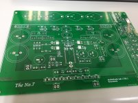
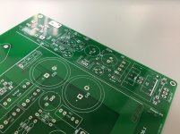
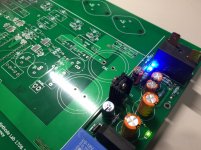
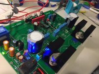
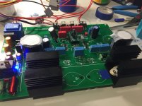
Finally, modulized GM was done! I use it as a test platform.
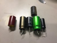
There're several feedback cap I've tested.
And,.... I love Elna Cerafine the most! Very vivid and gorgeous sounding!
My conclusion is :
Cerafine>Frolyt EKSU>Nichicon Muse BP =Elna Silmic II > Frolyt EKM>ROE EK
The input module uses 2N3958, and the power transistors are BUZ901/906.
Finally, modulized GM was done! I use it as a test platform.
There're several feedback cap I've tested.
And,.... I love Elna Cerafine the most! Very vivid and gorgeous sounding!
My conclusion is :
Cerafine>Frolyt EKSU>Nichicon Muse BP =Elna Silmic II > Frolyt EKM>ROE EK
The input module uses 2N3958, and the power transistors are BUZ901/906.
Attachments
- Home
- Amplifiers
- Solid State
- Goldmund Wiki and build 2017