Heck, KT, I delight in this!!
Looks like one of mine.....
Good to see you building, the world is your oyster.....
Hugh
Looks like one of mine.....
Good to see you building, the world is your oyster.....
Hugh
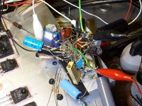
OS, you'll delight in this. This whirlwind of soldering prowess, not a foot away, is my headphone amp prototype. I want to get some blank PCB to do ground plane P-P prototypes.
- keantoken
It turned into the "jungle" !! 😱
OS
Thanks Hugh. I've been letting sheer inconvenience deter hands-on studies quite a bit. To use my bench I have to stand on a chair, which itself has less than a foot of clearance as all the space around it is covered in dismembered junk. For lack of suitable shelves or organizers, my bench is stacked and ready to landslide at the next unlucky attempt at stepping off the chair.
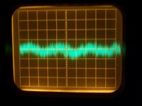
Nonetheless, the built regulator as in the schematic, shows <400uV of noise at 200uV/div (My 561B measures to 10uV/div!), at 5V output. I found no trace of oscillation on first power up with my 20MHz scope, then switched to my sensitive 561B. I used the older reference since I don't have suitable Jfets. No load connected.
It is stable with no output decoupling, but without the 20k bypassed with a cap output impedance is not very high. After I bypass it, I suspect output bypass will be more important. For lack of a signal generator, I will use my scope calibrator through a DC blocking capacitor to test pulse response, and output impedance will become evident too since the calibrator has a known output impedance.
- keantoken
Attachments

Output impedance with the schematic shown is 375mR. I will bypass R5 with a cap, and we'll see if it oscillates.
- keantoken
- keantoken
Looks nice and simple, KT, CCS followed by a CFP in shunt... certainly not up to your usual component count!! I really like this direction. To avoid too much AC gain which might cause overshoot and possible instability, divide R5 into two resistors, 10K pot on the rail in series with 10K to the CFP driver, and bypass only the pot.....
One more thing, however. Output voltage might drift substantially with variations in Vbe for the CFP driver.
Hugh
One more thing, however. Output voltage might drift substantially with variations in Vbe for the CFP driver.
Hugh
Last edited:
It is one of the fastest and best performing combinations you'll find. Without significantly higher component count you can't increase performance without degrading speed. Output impedance rivals that of all but the lowest ESR electrolytics, which theoretically makes it an excellent introduction to all things shunt.
Unfortunately the prototype's output impedance won't go below .25R. I don't know why. Oh, wait, it looks like my grounding wire has a bunch of inductance... Okay, fixed that, but now my scope is reading DC when it's in AC mode. Oh, it's oscillating at 25MHz! Finally, a sign that it's working as expected...
Time to add output bypass.
- keantoken
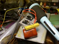
Okay, added a 220uF 35V Samwha cap I harvested from a computer monitor. The designer MUST have been a rabid amp builder because all the transistors were all audio amp part numbers. Samwha caps, and even the KSP42/T92.
No oscillation, and HF noise is lower than my scope can measure (lower than 10uV!). LF noise is below 80uV.
Using coax probe, I will see if output impedance is up to spec.
- keantoken
No oscillation, and HF noise is lower than my scope can measure (lower than 10uV!). LF noise is below 80uV.
Using coax probe, I will see if output impedance is up to spec.
- keantoken

It is one of the fastest and best performing combinations you'll find. Without significantly higher component count you can't increase performance without degrading speed. Output impedance rivals that of all but the lowest ESR electrolytics, which theoretically makes it an excellent introduction to all things shunt.
Unfortunately the prototype's output impedance won't go below .25R. I don't know why. Oh, wait, it looks like my grounding wire has a bunch of inductance... Okay, fixed that, but now my scope is reading DC when it's in AC mode. Oh, it's oscillating at 25MHz! Finally, a sign that it's working as expected...
Time to add output bypass.
- keantoken
That is why I am working so hard to refine layout techniques. Also making my own sprint templates (makros-german 😀) for "better than alex" results.
(below - my own work). 🙂 All that paint shop,
 paid off !!
OS
Attachments
OS, the fact that the oscillation frequency is so high is a sign that my layout is effective, and the fact that it was stable without output bypass until I slapped it with a 2.5' long coax.
Although, I daresay it may still be oscillating, just at higher than my 20MHz scope can show... Noise is low though which would seem to indicate otherwise.
- keantoken
Although, I daresay it may still be oscillating, just at higher than my 20MHz scope can show... Noise is low though which would seem to indicate otherwise.
- keantoken
Last edited:
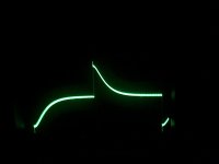
Does that plot look familiar?
- keantoken
Yep, it only slows down by the output cap. In the final layout if integrated to the driver board is the best time to decide the final output cap's value. One that will not show noise, mitigate layout inductance (i.e. no oscillations) and be fast. The type and make will play a role, and better be that certain cap fixed in BOM. How's the drift with the passive ref? Is Vbe steady enough?
Voltage has drifted down since first adjusting, which is not unexpected since Vbe decreases with temperature. I believe it was 200mV. So at 90V output, drift would be more than 3.6V, since these voltages would also increase heat of the device. So except at low voltages, the Jfet Vref is needed, and if that won't work well enough, perhaps a TL431 to servo.
- keantoken
- keantoken
Do you have a j201 around? That will work in Vbe margin and will show good enough regulation due to low idss. Maybe with a 1K Rs will be around its low tempco area. Will need a high Rref, but will run small current. I.e. no real heat, easier noise filtering by the snubber cap.
It is best to use small electrolytics, since they have highish ESR, and won't form resonance with the regulator's output inductance. At 90V, finding high-ESR electrolytics is no problem! Just use the closest 1uF 100V cap (NOT film).
As simulated, this regulator has an ultra-low output inductance of 10nH. So there's not much to improve upon except in local bypass to make up for added inductance between the regulator and load.
- keantoken
As simulated, this regulator has an ultra-low output inductance of 10nH. So there's not much to improve upon except in local bypass to make up for added inductance between the regulator and load.
- keantoken
Define in BOM. C-R-A-P magic cap.😀 Its a struggle! I always hunt them not to 0.1uF bypass the output cap in DCB1 or use a golden top dollar part.
Nope, no Jfets here.
- keantoken
What is your Vout right now that you saw the 200mV drift?
- Home
- Amplifiers
- Solid State
- Goldmund Mods, Improvements, Stability