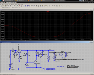
Kean, can you put J201 for R2 with 1k2 source resistor, 447K R5, and run that Zo plot again? Should be around 90Vout too.
So, output decoupling should be a reliable 160V, 1uF bypass. No film bypass, we need an inert, resistive, lossy cap here.
Gotta go.
Bye,
- keantoken
Gotta go.
Bye,
- keantoken
MiiB, the TL431 is slower and has lower impedance. About the only improvement is in bass, and if it's that important we can substitute zeners for R5.
These comparisons might help you decide which is more appealing.
- keantoken
TL431 is 36V max, isn't it?
So, output decoupling should be a reliable 160V, 1uF bypass. No film bypass, we need an inert, resistive, lossy cap here.
Gotta go.
Bye,
- keantoken
It may need be up to 22uF in practice. You will see on final layout when you will measure output noise and straight DC line in AC mode as integrated on the amp board.
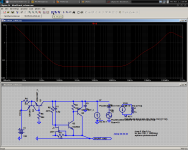
Little better around 100Hz. But significant in %. Especially at 20-30Hz. My model gives 200uA with Rs1k2. The main question remains if it will shrink drift. You will see in practice with OS's fets.
See ya.
See ya.
Getting into the uA, the Ib of Q2 becomes important. Simulated is 36uA. Simulated drift is 116mV/C. Beyond a point, it looks as if the drift will simply result from chaotically combining tempcos of Ib, Id, etc.
Also, increasing bass performance must also increase start-up delay.
Shunt voltage now reads 5.013. It looks as if the voltage is stabilizing. I will leave it on until I wake up.
Now I'm REALLY gone,
- keantoken
Also, increasing bass performance must also increase start-up delay.
Shunt voltage now reads 5.013. It looks as if the voltage is stabilizing. I will leave it on until I wake up.
Now I'm REALLY gone,
- keantoken
Since yesterday, output has drifted about .18mV. At 90V output this would be about 3.2V drift.
- keantoken
- keantoken
Given everything else was okay, what would be an acceptable drift?
By the way, a lot of fine hard work & tenacity on your and your kibitzers parts.
Thanks
By the way, a lot of fine hard work & tenacity on your and your kibitzers parts.
Thanks
What worries me most is not the drift after an hour of start-up, but before. When started cold, the reg will have higher voltage than normal. Since 90V will make the devices hotter, this will be worse than with my prototype.
- keantoken
- keantoken
Which single component do you think is temp. sensitive the MOST?
For instance if it where the cap, maybe back to back caps of opposite temp coefficients would be helpful. I did that once in a cold weather environment timer circuit once.
For instance if it where the cap, maybe back to back caps of opposite temp coefficients would be helpful. I did that once in a cold weather environment timer circuit once.
I think the most temp sensitive part is the CFP driver; it's base emitter junction affects the voltage divide function of the sensing circuit. The jfet pulls constant current, sure, but the tempco is not the same as the driver.
I've been thinking hard on this. There has to be another way.
What about returning to the 68K/470R solution, removing the jfet, and trying this:
#1 Add 300mV of degeneration to the CFP driver to elevate its base potential,
#2 Remove R2 470R, replace with a diode wired npn in series with a resistor.
I don't have time to figure the values just now, but if the diode wired npn were thermally coupled to the driver it would track, and this would preserve all currents and thus the output voltage. A guestimate for R2 would be 220R.
Hugh
Thermal epoxy a Large RED LED to the driver instead of the npn, drive it hard enough to raise its temp. up.
Thanks Salas,
In that case, inserting another npn in series with R2 may bring accurate tracking...... here's hoping the idea holds merit.
Hugh
In that case, inserting another npn in series with R2 may bring accurate tracking...... here's hoping the idea holds merit.
Hugh
Hugh, the degeneration will "mirror" the slave's Vbe and we'll be introducing another tempco. Simulated to check, it doesn't help.
It looks like the Jfet is the best bet.
The shunt was sitting on a larger heatsink, and I noticed that output voltage would increase or decrease depending on whether it was sitting flat (by about 200mV). I have some cardboard under it now and output voltage is now 4.957V.
Think winter time. Someone opens the door, cold air comes billowing in. The draft will increase the reg's output voltage. Using a TL431 would also allow us to increase R5, for better bass.
- keantoken
- Home
- Amplifiers
- Solid State
- Goldmund Mods, Improvements, Stability