Going to gb with nothing more than prompts from a Tektronix wielding Engineer with Cold FLux Joints.
I would rather build a bird house out of crackers.
I would rather build a bird house out of crackers.
OS,
I have built boards with ground planes an without ground planes and to be honest with I prefer the board with the plane. Can I measure the difference, no............go figure. To me the shunt happens to be the best regulator to use, Salas has proven this for the most part. This happens to be keans thread and he should have the final say........with our input of course.😉
Regards,
Jam
You must use the most compact and easy to accommodate IMHO. Even if with modest Zo and regulation it will be much better than what was there. If you don't want to mess with fet peculiarities, and go for a Zener ref, make sure you bypass it with 1000uF. There is grass even with 470uF. Will never be leds or norton and mkp but there is enough psrr for ripple at least. Time for decisions guys.
How about something similar to the Goldmund but shrunk down with all SMT devices, other then the output devices and what not of course. Well that and whatever other mods you guys deem it needs.
might be nice if you could cook it down to diy friendly single sided boards
and not make it too complicated
I would suggest to forget the Goldmund "competition" completely
it started out like that, sure
I hope the priorities are now to do the best you can think of, and not "just" a different Goldmund
at the present stage I think its about using laterals, mainly
and to find out what that takes
Im sure you guys can do it
so, as we have said to others before, why hurry
unless ofcourse you really are ready
Yes that's what I hope 🙂 I don't know every one seems to say that an SMT design sounds better, I imagine it's because of the shorter trace length and what not.
You mean SMD ?
well, it could make sense in some places, and do a mix of SMD and ordinary through hole components
for one, SMD components cant be used for jumpers
but might be a problem to get the parts
seems to me that many SMD parts are only available in larger quantities
well, it could make sense in some places, and do a mix of SMD and ordinary through hole components
for one, SMD components cant be used for jumpers
but might be a problem to get the parts
seems to me that many SMD parts are only available in larger quantities
I think that commonly used parts and some strategy with board layout would do the difference. Once someone asked here: "Holes? Why holes?" He meant that we could avoid the holes by soldering components at the tracks side. This would also make easier the use of the ground plane, I suppose (sorry, never etched a double layer board before).
SMT circuitry is appealing, for sure.
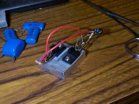
I am currently building the shunt regulator, but won't be able to test at HV, only say 30V. Uses 2SA1659Y, 2SC945P for CFP and 2N4126/C1659Y for CCS. Unfortunately my signal generator broke, so I won't be able to test it. I will at least be able to test stability.
- keantoken
I am currently building the shunt regulator, but won't be able to test at HV, only say 30V. Uses 2SA1659Y, 2SC945P for CFP and 2N4126/C1659Y for CCS. Unfortunately my signal generator broke, so I won't be able to test it. I will at least be able to test stability.
- keantoken
Attachments
As far as ground plane, SMD etc. Managing parasitics allows for faster design because of reduced instabilities, and I've found there is a positive correlation between SQ and lower stability compensation, quite simply.
- keantoken
- keantoken
SmartX, I wonder the same thing. Components always fall out of the holes, and if you bend the leads they are difficult to remove later. I think the only gain is increased shock and stress resilience. I might just try it.
- keantoken
- keantoken
Once someone asked here: "Holes? Why holes?" He meant that we could avoid the holes by soldering components at the tracks side.
I remember I suggested that
but we also often use the holes for "orientation"
with many parts and no holes it could get difficult
probably no problem to the most experienced builders
but the less skilled would be in trouble
but who would do his own double sided boards anyway
probably only the more experienced
Components always fall out of the holes, and if you bend the leads they are difficult to remove later.
after bending component legs, try to "widen" the legs just slightly more than width between holes
gently squeeze the legs when mounting
this way they will keep a small pressure in the holes
and easy to adjust for a nice look
now we are at it
I have often thought about how much stress we put on a resistor when soldering
especially with short cut legs and mounted tight to board
is this any issue at all ?
SMD, SMT you catch my drift 🙂 I've always known it as SMT (surface mount technology). I'm not sure what SMD stands for? The idea of mixed components with no holes is kind of appealing as well. If there are some part we have to order larger quantities for maybe it could be part of a PCB group buy with the more rare parts as well. Of course whoever did the group buy would have to be willing to buy and sort the pieces for everyone. But it's certainly doable.
SMD stands for SURFACE MOUNT DEVICE.
Maybe SMT isn't accessible to everyone, as SMD components are often sold in large quantities!
Maybe SMT isn't accessible to everyone, as SMD components are often sold in large quantities!
Last edited:
SMD/T ?? Many an eyeball is too bad to see them. It's getting hard to read the fairchild TO-92's as it is now. 🙁 I'll take my through hole stuff ... but I would try a SMD voltage module to start with (25 x 75mm - 3 postage stamps).
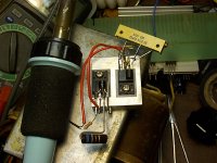
Keen , you do the point to point thing , too. 😎 I thought me and carlos were the only ones. I guess it is the only way to the TRUTH...
I did my first VB with sprint today. (below) I went with the to-126 version of the original goldmund with just a 3 device wilson mirror and added input CM. I will abuse it/test it. That is the only way to do it. I'll make separate boards for the BJT/FET versions.
OS
Attachments

- Home
- Amplifiers
- Solid State
- Goldmund Mods, Improvements, Stability