Er, it's normal to etch both sides at the same time... hasn't anybody here ever made a doublesided board?
w
w
Er, it's normal to etch both sides at the same time... hasn't anybody here ever made a doublesided board?
w
Yes that works when you have transparencies. NOT with iron on laser transfers.
Yes that works when you have transparencies. NOT with iron on laser transfers.
It works with iron on laser transfer also. Drill through the paper at your registration holes in the first transfer, iron it on, then drill through the board at the registration holes, align the second side transfer with the holes and iron on. Remove the paper and etch.
How do you iron on the second side without messing up the first iron on?
With great care.
w
See, I knew there was a catch...
To each his own. I prefer Trans but I do what I got to do. I mess up once in a while, but I got lots more boards and time than money for the board houses...
I try it, maybe I will like it.
To each his own. I prefer Trans but I do what I got to do. I mess up once in a while, but I got lots more boards and time than money for the board houses...
I try it, maybe I will like it.
Guys
Lets get something happening here. Where are we on the Power Supply issues.
And somebody post some mnemonics translation listings, I know I am not the brightest bulb in the lot, but you guys start popping em out like double barrel shot guns, and I get lost in hurry.
let some of us less knowledgeable guys in on the 411 too.
I know how to dish it out when I talk about something I am familiar with, but I try and keep it at lower level when newbies are in the room. THANKS
I am having fun with the new pcb software, so lets get me and a couple of other guys some schematics to build and try some pcb layouts with.
Uhh huh

 , You don't need 2X sides for LF audio , also a simple cap multiplier (like the original goldmund) would allow one to match or exceed the original.Just short lines , separate 120v trafo and a regulator/multiplier will exceed the stupid doubler/multiplier on the original. 90% is getting the front end right , it is what makes the sound.
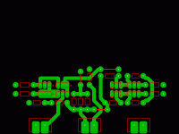
I think I can even get nearly jumperless with my new toy (sprint layout-below).
OS
Attachments
Hey OS
Those Octo Pads, are they self de-fluxing or they prevent cold joints...
I am just teasing.
Looking good, showing off is great. I like the system so far.
What schmo are you working from?
Thanks
Those Octo Pads, are they self de-fluxing or they prevent cold joints...
I am just teasing.
Looking good, showing off is great. I like the system so far.
What schmo are you working from?
Thanks
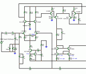
Them pads are just "fat". I am workin' from ..(below-best candidate). Soon.. w/splan , prettier schematics will be the order of the day. Front end will have every mod known to play with while remaining professional. I had to learn how to make my own "macro's" , I now have my own library of custom HD patterns. 🙂Hey OS
Those Octo Pads, are they self de-fluxing or they prevent cold joints...
I am just teasing.
Looking good, showing off is great. I like the system so far.
What schmo are you working from?
Thanks
OS
Attachments
Is there going to be 2 trains of thought here?
One a Testing/Development 3 or 4 separate board SYSTEM
Two a complete one or two board ready for testing, just to see if it works before sending it to a board house for mass reproduction.
OR
????
With at least OS and ALEX on board I can lend a hand or what ever...
I am just saying lets run up a flag and see who salutes...
Thanks...
Is there going to be 2 trains of thought here?
One a Testing/Development 3 or 4 separate board SYSTEM
Two a complete one or two board ready for testing, just to see if it works before sending it to a board house for mass reproduction.
OR
????
With at least OS and ALEX on board I can lend a hand or what ever...
I am just saying lets run up a flag and see who salutes...
Thanks...
No and yes... This voltage board will gracefully accommodate the basic 4 tranny original VAS or the 8 device beta enhanced version. Before I would ever send a board off for "mass production" , it would have to be absolutely exceptional in both stability , reliability , and looks/layout. Of course it would have to sound exceptional, as well....and to a wide range of people.
We should be able to do it with 2 boards. The big one (OPS/HV PS) , and the little one (VAS/LTP). What is "nicer" about this , is that the small signal stages are not even close to the power stages... not even on the same board. won't be stuck with a bad design , just rework the board - plug it in !
Personally , this coincides with my development of my symasym board (CX) , so I will be the first to hear THIS voltage stage (10 days from now-I need FR-4). I will start the "Big" board , but only if it incorporates my plugin. IF , for any reason this is unacceptable , screw everybody
 ... as I will just go ahead anyways and make something real. 1725 posts between the 2 threads and NO product or prototype , geez. I salute to my own flag!! 😀
OS
Last edited:
Well, if you cover the other side with a plastic coating (adhesive, sticker) I think it would remain unetched.
really, so like really wide packing tape you think will stick and not come off?
Hi Os, Goldmund uses 60V AC as it is the same trans used for +_80V DC. Look at Krill, it is very similar power supply, so doubler is not so stupid solution, only one transformator(or two if mooblocks are wanted).
dado
dado
Uhh huhOS
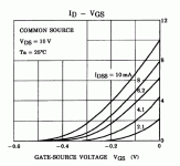
Its not that hard to consider a better Tempco region in a JFET Norton Vref's type CCS. A 4mA IDSS K170GR shows -0.5V pinch off (-Vp) on its datasheet. Vgs(0Tc) will be (by that formula I mentoned) 0.5-0.63=-0.13V. Its Ids-Vgs curves show 1.8mA Ids at Vgs0TC.
IdZero=(0.63/0.5)squared*1.8=2.857mA. A proper source resistor for that would be Rs(0TC)=0.13V/2.857mA=45.5R. Our Norton ref resistor for say 90V B+ to voltage stages of the amp will need be (90-vbe)/2.857=31.29K. Practically you stick a 33K 1W and a 100R Rs trimmer in Kean's CCT and you play midway travel near Zero TC. The large impedance can be cleaned easily for self noise by a 2u2 MKP with no real ESR to keep noise bugging up high in frequency. The residual 33K resistor noise is 23.4nVrtHz. That was it.
Attachments
plotter
Draw the pattern, with etch resistant ink. A plotter uses tiny re-fill ink bottles, bit of a hassle to locate the proper ink though.
Marker holes are not an issue with plastic spray, i've got a heated jacuzzi etch tub, the 2-stage etch job is no big deal.
I totally despise via riveting.
Laser printing isn't me cup of tea for double sided boards and i've spent loads on transparents, general use and PCB specials since their first release.
(H..., me went out eating yesterday eve, when me gots home there was no dig tv, no dig telephone, and no internet. 15hrs of tight buttocks, how come a hick as me lived to see the day i became a web junkie)
Attachments
Last edited:
Uhh huh
Can someone inform on what all the headbanging is going around for? I was lost at the beginning.
- keantoken
This is really crazy!!!😱1725 posts between the 2 threads and NO product or prototype!
And there are boards going into production...


- Home
- Amplifiers
- Solid State
- Goldmund Mods, Improvements, Stability


