My F2J with the very generously provided SS JFETs is just about done. I finished all the boards and mounted them in the chassis. Just need to wire it and test it. So close to the finish line.
Thanks again codyt and Mr. Pass.
Excited to hear what you think!
Randy,
The boards look great and I know the quality is first class. I wish I had more time to build them. Maybe in the future.
Also looking foreward to how you like it! What did you use as schematic, as there are some many versions now...
Thanks!
I used the schematic found on the First Watt website. I need to sort out a problem, but initial listening it sounded good.
My pair arrived today!
Thanks once more to Nelson and codyt, you guys made my day wonderful🙂
Regards,
Thanks once more to Nelson and codyt, you guys made my day wonderful🙂
Regards,

Hi Cody,Regarding R24 - I’ve noticed that small changes here make a big impact.
yes, that CCS FB R24 is like a trimmer for balancing the opposite currents in the CCS and the SemiSouth.
R24 is also related to the value of the source resistors,
when changing source resistors from 0.22 to 0.33 then R24 need to be changed accordingly ex. 800 to 1200 to maintain the same balancing act.
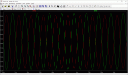
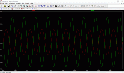
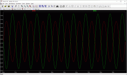
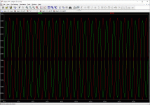
Here are some screenshots from simulating different values.
The first three with source resistors 0.22 and R24 500-700-1000
that fourth with source resistors 0.33 and R24 1200
green trace: current Semisouth
red trace: current CCS
Attachments

Hi Cody,
yes, that CCS FB R24 is like a trimmer for balancing the opposite currents in the CCS and the SemiSouth.
R24 is also related to the value of the source resistors,
when changing source resistors from 0.22 to 0.33 then R24 need to be changed accordingly ex. 800 to 1200 to maintain the same balancing act.
Here are some screenshots from simulating different values.
The first three with source resistors 0.22 and R24 500-700-1000
that fourth with source resistors 0.33 and R24 1200
green trace: current Semisouth
red trace: current CCS
Hi Danny, thank you for posting these measurements. Please help a novice such as myself understand which of the graphs for the 0.22ohmsource resistors and R24 values are ideal for proper operation and why this is so.
I’ve looked at all 4 screenshots and tried to compare them but the amplitudes are all different so not completely comparable, at least not to an untrained person like myself. The closest “comparison” I can make is that the 0.22 ohm source resistor and 1K ohm combination “look most similar”. If I’m way off the mark, and I probably am, please explain.
Thank you
R24 helps establish the amount of AC modulation in the CCS. This AC modulation is the ‘helping hand’ that helps take the load off the output transistor and lower distortion. I’m not sure what value NP landed on for the AJ, but he set the standard of 50% AC gain contribution from the Aleph current source in Zen v2.
A fun experiment is to lift one leg of R24, which essentially disables the Aleph/modulated current source and creates a standard CCS. Still sounds fantastic, but distortion increases considerably. By a factor of 10 I think.
R24 helps establish the amount of AC modulation in the CCS. This AC modulation is the ‘helping hand’ that helps take the load off the output transistor and lower distortion. I’m not sure what value NP landed on for the AJ, but he set the standard of 50% AC gain contribution from the Aleph current source in Zen v2.
Thanks Cody, so how is 50% value for R24 calculated in reference to the source resistors?
A fun experiment is to lift one leg of R24, which essentially disables the Aleph/modulated current source and creates a standard CCS. Still sounds fantastic, but distortion increases considerably. By a factor of 10 I think.
I just may try that. Thanks!
I believe you run a steady AC wave through the amp and look at the AC current across the current sense resistors at the output vs the AC current across the source resistor of the CCS. The CCS contribution should be roughly half of the total. Page 3 in ZenV2 is what I’m referencing.
I believe you run a steady AC wave through the amp and look at the AC current across the current sense resistors at the output vs the AC current across the source resistor of the CCS. The CCS contribution should be roughly half of the total. Page 3 in ZenV2 is what I’m referencing.
Thanks Cody, I’ll give it a read.
Any schema to use these nice parts when they arrive at my home?
The dynamic current source in the J2 is IMHO better in circuitry terms than the Aleph CS.
At least that would be my choice.
Otherwise the two circuits are very similar.
And I would NOT adjust bias with the drain resistor, but rather the input CCS.
Like in the UDNeSS.
Patrick
The 2 Semisouth Gifts arrived last week.
Many thanks at codyt and Nelson Pass to make this possible.
Now planing how to use them
Had a redesign for my AlephJ PCB in the Pipe. When PCB is done, this could be a good possibility to upgrade the J.
Thanks a lot.
Many thanks at codyt and Nelson Pass to make this possible.
Now planing how to use them
Had a redesign for my AlephJ PCB in the Pipe. When PCB is done, this could be a good possibility to upgrade the J.
Thanks a lot.
And I would NOT adjust bias with the drain resistor, but rather the input CCS.
Like in the UDNeSS.
Hi Patrick,
What are the benefits from adjusting the bias with the input ccs?
Hubert
> What are the benefits from adjusting the bias with the input ccs?
You take care of the variations in Vgs without changing open loop gain, or amount of negative feedback.
Plus that you have nice, low-noise, fixed resistor doing the biasing.
Patrick
You take care of the variations in Vgs without changing open loop gain, or amount of negative feedback.
Plus that you have nice, low-noise, fixed resistor doing the biasing.
Patrick
Hi,Hi Danny, thank you for posting these measurements. Please help a novice such as myself understand which of the graphs for the 0.22ohmsource resistors and R24 values are ideal for proper operation and why this is so.
It depends what your goals are.
The CCS base resistor R24 sets the balance of the dynamic current of both output devices.
If your goal is maximum power then the dynamic current of both output devices should be equal but opposite: as one goes up the other should go down.
This gives max power and both devices never switch off.
See graphic 1
If your goal is best subjective sound then you can play with this resistor and maybe you also arrive at 50% CCS, see graphic 2
Remember if you change the source resistors, this will also change the balance of the dynamic current of the CCS and SemiSouth, so you need to adjust the R24 also.
I've also included the Ltspice files, add traces I(R16) and I(R18) to see the dynamic current of the output devices.
Attachments

Hi,
It depends what your goals are.
The CCS base resistor R24 sets the balance of the dynamic current of both output devices.
If your goal is maximum power then the dynamic current of both output devices should be equal but opposite: as one goes up the other should go down.
This gives max power and both devices never switch off.
See graphic 1
If your goal is best subjective sound then you can play with this resistor and maybe you also arrive at 50% CCS, see graphic 2
Remember if you change the source resistors, this will also change the balance of the dynamic current of the CCS and SemiSouth, so you need to adjust the R24 also.
I've also included the Ltspice files, add traces I(R16) and I(R18) to see the dynamic current of the output devices.
Thank you Danny! I guess I’ll be trying to learn Ltspice next.
- Home
- Amplifiers
- Pass Labs
- Giveaway - SJEP120R100 pair