Its both - the loudspeakers power response is the source and the rooms power response is the sink. The steady state SPL in the room is what lies in the middle. They both need to be correct.
I'm aware of that but the question is what is correct in this context and how can it be presented by measurements?
It seems like a more complicated form of data processing prior to presentation. Theoretically it is possible, but not practical. Since the sink part is primarily involved with the amount of reflected energy, depending on the absorption characteristics and how many reflections one wishes to calculate until the reflection is below a certain level.I'm aware of that but the question is what is correct in this context and how can it be presented by measurements?
DBMandrake wrote;
“Insufficient reflection free time and an inability to draw conclusions from a single point measurement being the two main issues. Neither of these issues is going away in a listening room with in-situ speakers. To improve high frequency response flatness of a speaker requires properly conducted anechoic or pseudo-anechoic measurements (with sufficiently long window times) on and off axis. Not placing a microphone stand on the sofa and pressing "go" on an auto-eq system.”
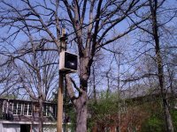
This is more important than most realize. Working on the Unity and then Synergy horns, it was convenient to build a tower that i could lift the speaker off he ground and place the microphone at a proper distance (often needs to be more than one meter). This insured you only have the speaker in the measurement at least so far as dealing with a woofer to mid crossover with valid data.
That is another thing that many don’t realize, these measurements also contain noise not part of the loudspeakers response.
This is usually present at the low end of the response and a real give away of a noise limited measurement is when the lf response rolls off normally but after a bit, makes a notch and then comes back up making it look like you have free or unexpected bass response. While that response might happen indoors, it can’t happen acoustically outdoors with normal woofers etc.
With Arta for example, one can average 3 or more sequences and force the noise floor downward. With a TEF machine, you have to set the mic gain up high but not clipping.
What may not have been mentioend is that to a degree you can examine the room reflections with ARTA.
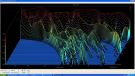
Here is sonogram view of a Burst decay of a very directional speaker taken at the listing position.
In this display, intensity, frequency and a scale based on wavelength (instead of time) is used, in this view, time is now wave periods. In the ETC i posted earlier, one can see a very visible floor bounce which is the first significant thing to arrive after the direct sound.
In this view, a reflection that caused a delayed signal of say 10 periods at 500Hz, will also make one at 20 periods at 1000Hz and so on. AS a result, delayed or reflected sounds show up as an arc.
Best,
Tom Danley
“Insufficient reflection free time and an inability to draw conclusions from a single point measurement being the two main issues. Neither of these issues is going away in a listening room with in-situ speakers. To improve high frequency response flatness of a speaker requires properly conducted anechoic or pseudo-anechoic measurements (with sufficiently long window times) on and off axis. Not placing a microphone stand on the sofa and pressing "go" on an auto-eq system.”
This is more important than most realize. Working on the Unity and then Synergy horns, it was convenient to build a tower that i could lift the speaker off he ground and place the microphone at a proper distance (often needs to be more than one meter). This insured you only have the speaker in the measurement at least so far as dealing with a woofer to mid crossover with valid data.
That is another thing that many don’t realize, these measurements also contain noise not part of the loudspeakers response.
This is usually present at the low end of the response and a real give away of a noise limited measurement is when the lf response rolls off normally but after a bit, makes a notch and then comes back up making it look like you have free or unexpected bass response. While that response might happen indoors, it can’t happen acoustically outdoors with normal woofers etc.
With Arta for example, one can average 3 or more sequences and force the noise floor downward. With a TEF machine, you have to set the mic gain up high but not clipping.
What may not have been mentioend is that to a degree you can examine the room reflections with ARTA.
Here is sonogram view of a Burst decay of a very directional speaker taken at the listing position.
In this display, intensity, frequency and a scale based on wavelength (instead of time) is used, in this view, time is now wave periods. In the ETC i posted earlier, one can see a very visible floor bounce which is the first significant thing to arrive after the direct sound.
In this view, a reflection that caused a delayed signal of say 10 periods at 500Hz, will also make one at 20 periods at 1000Hz and so on. AS a result, delayed or reflected sounds show up as an arc.
Best,
Tom Danley
Attachments
DBMandrake wrote;
That is another thing that many don’t realize, these measurements also contain noise not part of the loudspeakers response.
This is usually present at the low end of the response and a real give away of a noise limited measurement is when the lf response rolls off normally but after a bit, makes a notch and then comes back up making it look like you have free or unexpected bass response.
Tom Danley
This is frequently seen acompanying a truncation error. The usual band limited system, having no DC response, will have a decaying tail that wobbles around zero pressure while it dies away. If you chop the tail at an arbitrary point you are frequently forcing some amount of DC offset into the response. This gives you apparent LF response that doesn't really exist.
David S.
Nice setup Tom. That has to result in some good data.
BTW, what is that crazy multi-cell thing on the roof? It looks like a 15 cell horn with each cell broken up into 4 parts. RCA?
BTW, what is that crazy multi-cell thing on the roof? It looks like a 15 cell horn with each cell broken up into 4 parts. RCA?
It keeps the birds from flying into the windows.Nice setup Tom. That has to result in some good data.
BTW, what is that crazy multi-cell thing on the roof? It looks like a 15 cell horn with each cell broken up into 4 parts. RCA?
This is frequently seen acompanying a truncation error. The usual band limited system, having no DC response, will have a decaying tail that wobbles around zero pressure while it dies away. If you chop the tail at an arbitrary point you are frequently forcing some amount of DC offset into the response. This gives you apparent LF response that doesn't really exist.
David S.
I see this as the more typical problem.
What I do is have a window that tapers, which this still does not insure no DC in the truncated impulse (as is required in the measurement). However, if you allow the window taper to vary in width and the truncation point to vary slightly, an algorithm can find that window which has no DC and this gives a "decent" LF response for a given window length. But the response is still not exactly correct because it has been truncated. The "Q" of the HP is always higher than what is shown, although you can get the frequency pretty close.
Best is to extend the impulse response past the truncation point as Bill Waslo does. This is very effective.
In Kind
Your hostile and derogatory post, referenced here, was missed until a friend pointed it out to me.
So in kind, my response to it is posted here now.
WHG
Originally Posted by whgeiger
Facts:
2a) Operation of a compression driver at and below system resonance is contraindicated, due to the attendant increase in distortion products in this region.
Your study does not prove your assertion and did not test compression drivers at and below system resonance as this requires the presence of a horn. Your study lacks the prerequisite rigor to prove much of anything, beyond that already known. My characterization of distortion is more general than yours as well; so, your attempt here to challenge my statement is specious at best. For another dissenting view see [1] and for a study yielding different results see [2]
2b) To reduce driver diaphragm displacement with a decline in frequency requires a high pass filter slope > 12 dB per octave.
Home use, may or may not, present a challenge to a particular compression driver/horn combination, depending on the customer who buys it. The manufacturer has absolutely no control over how a product it makes may be used once it is sold. The degree to which the performance limits of such assemblages are approached, depends on the size of the listening space, the size of the group being entertained, the dynamics of the program being reproduced, the resulting level setting of the system being used, and the slope and frequency of the high pass filter protecting the driver. How well a product survives in a marketplace will be measured by the number of warrantee returns its manufacturer receives.
2c) Driver loading (or the absence thereof) provided by a loudspeaker enclosure (horn included) is not a matter of mythology. In conical horns, as well as those asymptotically conical, the early decline of driver loading and the absence of a material [Fc] are well known and understood.
3) Under these conditions, a minimum of a 3-way partition of the audible spectrum is needed; e.g., 20-200, 200-2000, 2000-20,000 Hz. This fact is particularly relevant for an all-horn system.
Facts:
3...
It is your claim that what I presented here is fallacious, so the burden of proof remains with you, the accuser. So far it is opinionated responses by you that are being presented as refutation.
4) To mitigate beaming at the upper limit (determined almost entirely by the perimeter size and geometry of the effective piston radiating area), dispersive elements must be introduced such as an acoustic lens, passage bifurcation, or other beam spreading mechanisms. All drivers, horn loaded or not, exhibit high frequency beaming. This occurs when signal wave length approaches or becomes smaller than radiator dimensions.
The narrowing in the radiation pattern for a 1” aperture would be expected to become acute at frequencies above 10kHz. So, if your claim is true, then something is mitigating the beaming.
Facts:
4a) The laws of acoustics dictate the beaming; unless of course, you mitigate it. In your case, this is achieved by introducing a foam acoustic lens and a geometric discontinuity in the horn neck. In the later case flare curvature increases rapidly from the compression driver exit and then steadily declines as a cone asymptote is approached. To mitigate the inevitable reflectance at the mouth, a toroidal surface of arbitrary dimensions is introduced. Here curvature abruptly increases again.
Just because the outer surface of an acoustic lens is convex does not necessarily make it a convergent lens. If the foam is not contributing to energy spreading, then neck and phase plug geometry alone are mitigating the high frequency beaming. Here again, your assertion uses misquotation as the premise.
There are many ways to design a loudspeaker system. We differ in approach and as to what is important when doing that.
You bring it on! It is you that chooses to question my veracity. Again the burden of proof remains with you. So far, your delivery on that obligation remains unconvincing.
Only point and line sources radiate waves that have circular wave fronts. For the output of a monopole or dipole radiator to approach this pattern, signal wave length must be many times greater than radiator dimensions. By the way, the presence of a baffle, infinite, finite, flat or contoured; is NOT required for this phenomenon to present itself. In fact beaming occurs in the absence of a baffle as demonstrated in [3] below.
Your presentation here, laced with grammatical errors and misspellings, brings into question your claim of perfection as well. From time to time, Goliath needs to be reminded, that David remains only a stone’s throw away. For now, the award of a “Klipsch Button” should be sufficient to maintain your grade point average here.
References:
[1] File: CmpDrvDst-GvR.doc
[2] Files: AES-P7718-p1/7.pdf
[3] File: BeranekAcoustics-p105-f4.13.pdf
Your hostile and derogatory post, referenced here, was missed until a friend pointed it out to me.
So in kind, my response to it is posted here now.
WHG
Originally Posted by whgeiger
Facts:
2a) Operation of a compression driver at and below system resonance is contraindicated, due to the attendant increase in distortion products in this region.
Fact: nonlinear distortion in a compression driver is inaudible - see my AES papers on this.
Your study does not prove your assertion and did not test compression drivers at and below system resonance as this requires the presence of a horn. Your study lacks the prerequisite rigor to prove much of anything, beyond that already known. My characterization of distortion is more general than yours as well; so, your attempt here to challenge my statement is specious at best. For another dissenting view see [1] and for a study yielding different results see [2]
2b) To reduce driver diaphragm displacement with a decline in frequency requires a high pass filter slope > 12 dB per octave.
To "reduce it" correct, but the 6 dB downward slope does dramatically reduce the excursion requirements. In home use excursion below resonance is not an issue at all.
Home use, may or may not, present a challenge to a particular compression driver/horn combination, depending on the customer who buys it. The manufacturer has absolutely no control over how a product it makes may be used once it is sold. The degree to which the performance limits of such assemblages are approached, depends on the size of the listening space, the size of the group being entertained, the dynamics of the program being reproduced, the resulting level setting of the system being used, and the slope and frequency of the high pass filter protecting the driver. How well a product survives in a marketplace will be measured by the number of warrantee returns its manufacturer receives.
2c) Driver loading (or the absence thereof) provided by a loudspeaker enclosure (horn included) is not a matter of mythology. In conical horns, as well as those asymptotically conical, the early decline of driver loading and the absence of a material [Fc] are well known and understood.
3) Under these conditions, a minimum of a 3-way partition of the audible spectrum is needed; e.g., 20-200, 200-2000, 2000-20,000 Hz. This fact is particularly relevant for an all-horn system.
The impression I get, from your many posts here and elsewhere, is that you believe that only you are the author of facts, and that statements expressed by others, are opinions to remain in question, because you have no peers.Thats not the way I see and I am not disatisfied with the results. But these aren't "facts" they are opinions.
Facts:
3...
Facts 3 ... are opinions offerd with no substantiation.
It is your claim that what I presented here is fallacious, so the burden of proof remains with you, the accuser. So far it is opinionated responses by you that are being presented as refutation.
4) To mitigate beaming at the upper limit (determined almost entirely by the perimeter size and geometry of the effective piston radiating area), dispersive elements must be introduced such as an acoustic lens, passage bifurcation, or other beam spreading mechanisms. All drivers, horn loaded or not, exhibit high frequency beaming. This occurs when signal wave length approaches or becomes smaller than radiator dimensions.
Once again, this is untrue and proven by the data for the Summa shown on my website which has a constant DI up to 20 kHz for a 1" aperature, which should, according to your claims, beam like crazy.
The narrowing in the radiation pattern for a 1” aperture would be expected to become acute at frequencies above 10kHz. So, if your claim is true, then something is mitigating the beaming.
Facts:
4a) The laws of acoustics dictate the beaming; unless of course, you mitigate it. In your case, this is achieved by introducing a foam acoustic lens and a geometric discontinuity in the horn neck. In the later case flare curvature increases rapidly from the compression driver exit and then steadily declines as a cone asymptote is approached. To mitigate the inevitable reflectance at the mouth, a toroidal surface of arbitrary dimensions is introduced. Here curvature abruptly increases again.
Again untrue - the foam has no effect on directivity, and if it did (think about it!!) the foam would narrow the directivity because it is a convergent lense! And I also have data to prove that.
I first tried to affect the directivity with the foam, but to widen the directivity would have required a concave surface NOT a convex one. But the fact is that there was very little change in directivity. So I opted to use a convex outer surface, which, if it does anything, makes the directivity narrower, not wider.
I think you have the physics wrong.
Just because the outer surface of an acoustic lens is convex does not necessarily make it a convergent lens. If the foam is not contributing to energy spreading, then neck and phase plug geometry alone are mitigating the high frequency beaming. Here again, your assertion uses misquotation as the premise.
There are many ways to design a loudspeaker system. We differ in approach and as to what is important when doing that.
Different approaches is fine, but quoting falsehoods as "facts" is not. If you want to argue the math and physics then bring it on. You'll not win that one.
You bring it on! It is you that chooses to question my veracity. Again the burden of proof remains with you. So far, your delivery on that obligation remains unconvincing.
Even Don Keele got the directivity at HFs wrong and simply could not understand how the Summa waveguide was able to do what it does. That's because he too misunderstood the physics.
Beaming from a source is happens when the source is flat and in an infinite baffle. A flat disk at the end of a waveguide is NOT an infinite baffle and DOES NOT have to beam according to the physics. At the mouth the wavefront is not flat any longer and will not beam when placed in in a baflle or otherwise. However, If the waveguide is not precsiely an OS then the wavefront at the mouth will not be a sufficiently coherent spherical section to radiate properly and it will beam. Only an OS countour will allow this effect for a circular wavefront. - Thats the physics and the data proves it.
Only point and line sources radiate waves that have circular wave fronts. For the output of a monopole or dipole radiator to approach this pattern, signal wave length must be many times greater than radiator dimensions. By the way, the presence of a baffle, infinite, finite, flat or contoured; is NOT required for this phenomenon to present itself. In fact beaming occurs in the absence of a baffle as demonstrated in [3] below.
I didn't get a 4.0 average in my Physics PhD by sleeping in class.
Your presentation here, laced with grammatical errors and misspellings, brings into question your claim of perfection as well. From time to time, Goliath needs to be reminded, that David remains only a stone’s throw away. For now, the award of a “Klipsch Button” should be sufficient to maintain your grade point average here.
References:
[1] File: CmpDrvDst-GvR.doc
[2] Files: AES-P7718-p1/7.pdf
[3] File: BeranekAcoustics-p105-f4.13.pdf
Attachments
-
AES-P7718-p7.pdf54.7 KB · Views: 137
-
AES-P7718-p6.pdf82.9 KB · Views: 127
-
AES-P7718-p5.pdf162 KB · Views: 113
-
AES-P7718-p4.pdf102.2 KB · Views: 102
-
AES-P7718-p3.pdf138.3 KB · Views: 167
-
AES-P7718-p2.pdf67.8 KB · Views: 131
-
AES-P7718-p1.pdf64.2 KB · Views: 152
-
CmpDvrDst-GvR.doc43 KB · Views: 170
-
BeranekAcoustics-p105-f4.13.pdf178.5 KB · Views: 121
Last edited:
Its not worth discussing any of this any longer, and your references are clear proof of why. Jon Risch was completely wrong and the edited discussion only shows me that he did not understand the paper. I'll stand by it as it is correct as anyone who has actually followed up on it will attest to. The second paper is not worth discussing because it is so poorly done. It will never see publication in the Journal and as such is not peer reviewed. Our paper was peer reviewed. If these are the people that you side with then be my guest.
Your hostile and derogatory post, referenced here, was missed until a friend pointed it out to me.
The impression I get, from your many posts here and elsewhere, is that you believe that only you are the author of facts, and that statements expressed by others, are opinions to remain in question, because you have no peers.
Ahhh, Bingo ....🙂
I was as shocked to hear of the Gedlee's multiple subwoofer setup 10 yrs after we had done such in recording studio's and we weren't the first.
Hard to beat the good Doc at his science .................
 suit on ...
Last edited:
Here are some quotes that all of us would do well to keep in mind in heated discussions: my journey & geotech study: GAME OF ENGINEERING - KARL TERZAGHI
It's not aimed at anyone in particular, but I thought this thread could be as good place as any to post it.
-Bjørn
It's not aimed at anyone in particular, but I thought this thread could be as good place as any to post it.
-Bjørn
Its not worth discussing any of this any longer, and your references are clear proof of why. Jon Risch was completely wrong and the edited discussion only shows me that he did not understand the paper. I'll stand by it as it is correct as anyone who has actually followed up on it will attest to. The second paper is not worth discussing because it is so poorly done. It will never see publication in the Journal and as such is not peer reviewed. Our paper was peer reviewed. If these are the people that you side with then be my guest.
Quote AES (This notice appears at the top of each convention paper):
"The papers at this Convention have been selected on the basis of a submitted abstract and extended précis that have been peer reviewed by at least two qualified anonymous reviewers."
WHG
The abstract and Precis have been reviewed - but NOT the paper. A preprint is NOT the same as a paper published in the Journal. I thought you would have known that.
Again?
I am well aware that peer review of the convention paper was made via its "abstract and extended précis", which presents only the essence of its content. On that basis, the reviewers believed the entire paper worthy of presentation at an AES convention.
I am sure that the paper authors, fellow AES members, will be delighted to hear about your contempt for their work and presentation skills.
For me, the form of presentation does not matter, just the validity of its content, even when the translation from Spanish to English has aparently been problematic for its authors.
WHG
Its not worth discussing any of this any longer, and your references are clear proof of why. …… The second paper is not worth discussing because it is so poorly done. It will never see publication in the Journal and as such is not peer reviewed. Our paper was peer reviewed. If these are the people that you side with then be my guest.
The abstract and Precis have been reviewed - but NOT the paper. A preprint is NOT the same as a paper published in the Journal. I thought you would have known that.
I am well aware that peer review of the convention paper was made via its "abstract and extended précis", which presents only the essence of its content. On that basis, the reviewers believed the entire paper worthy of presentation at an AES convention.
I am sure that the paper authors, fellow AES members, will be delighted to hear about your contempt for their work and presentation skills.
For me, the form of presentation does not matter, just the validity of its content, even when the translation from Spanish to English has aparently been problematic for its authors.
WHG
Last edited:
Here are some quotes that all of us would do well to keep in mind in heated discussions: my journey & geotech study: GAME OF ENGINEERING - KARL TERZAGHI
It's not aimed at anyone in particular, but I thought this thread could be as good place as any to post it.
-Bjørn
I loved that - thanks!
Certainly agree with that.Here are some quotes that all of us would do well to keep in mind in heated discussions: my journey & geotech study: GAME OF ENGINEERING - KARL TERZAGHI
It's not aimed at anyone in particular, but I thought this thread could be as good place as any to post it.
-Bjørn
Hello Bjørn,
As a geologist having teaching engineering geology more than 35years I am in fully agreement with Terzaghi
(BTW : his work on fluid dynamics inspired, for a part, my method to design horns...)
Best regards from Paris, France
Jean-Michel Le Cléac'h
As a geologist having teaching engineering geology more than 35years I am in fully agreement with Terzaghi
(BTW : his work on fluid dynamics inspired, for a part, my method to design horns...)
Best regards from Paris, France
Jean-Michel Le Cléac'h
Here are some quotes that all of us would do well to keep in mind in heated discussions: my journey & geotech study: GAME OF ENGINEERING - KARL TERZAGHI
It's not aimed at anyone in particular, but I thought this thread could be as good place as any to post it.
-Bjørn
Noble or Not?
“Engineering is a noble sport which calls for good sportsmanship.”
Karl Terzaghi
Only when this is true, do the rules of noble engagement apply;
otherwise, the “sport” is not “engineering” and rules to be applied are entirely different.
WHG
Here are some quotes that all of us would do well to keep in mind in heated discussions: my journey & geotech study: GAME OF ENGINEERING - KARL TERZAGHI
It's not aimed at anyone in particular, but I thought this thread could be as good place as any to post it.
-Bjørn
“Engineering is a noble sport which calls for good sportsmanship.”
Karl Terzaghi
Only when this is true, do the rules of noble engagement apply;
otherwise, the “sport” is not “engineering” and rules to be applied are entirely different.
WHG
Hi,
if the throat diameter of a comp. driver exit is meaningless for the upper frequency limit of constant sound dispersion in an OSWG, why do all big drivers die at 8-10kHz?
Is it because they usually have a bigger VC with a higher inductance, diaphragm breakup or even something elese i can't imagine?
if the throat diameter of a comp. driver exit is meaningless for the upper frequency limit of constant sound dispersion in an OSWG, why do all big drivers die at 8-10kHz?
Is it because they usually have a bigger VC with a higher inductance, diaphragm breakup or even something elese i can't imagine?
My guess is with the bandlimited design of most compression driver, the phaseplug along with driver mass and motor is optimized to deliver high spl only to within some range, beyond that is "cutoff" just like bandpass subwoofer can only deliver higher efficiency for a narrow range of passband
- Home
- Loudspeakers
- Multi-Way
- Geddes on Waveguides