soongsc said:
This way of putting it gives me the impression the conclusion is drawn from gut feeling or engineering intuition only. No varying radius samples were tested.
My response implies that there is no theoretical reason to vary the radius. I don't guess at things. Unless someone can give me some rational reason why varying the radius would work better why should I try it? Because someone elses "gut feeling or engineering intuition" says that I should test it? My speakers have been designed on strictly objective scientific principles. This approach has worked very well for me thus far and I see no reason to change now.
JLH said:Jean-Michel,
A little off-topic here, but could you post the input parameters you use to model the TAD driver in Hornresp? Thank you.
Rgs, JLH
Getting an accurate set of parameters for a compression driver can be tricky business because virtually no manufacturer supplies enough information to get a good model. You have to do some tests for yourself. The way I do it has worked well for me.
In a program like SPEAK, you use what data you have from the manufacturer and see if you can get a comparable electrical impedance in the model and the real thing - usually things are way off. Then I place the driver face down such that the throat is blocked and measure the electrical impedance. You have to estimate the interior volume of the cavity that is created, but varying this in the model should allow a decent fit as there are now no radiation components to worry about - the model is very simple and should be easily fit.
Then you can take the back off and run the impedance again. This will give you a better idea of what the parameters are by fitting this - this usually gives you a good idea of wht the rear volume compliance and resistance are.
At this point you may have enough, but if not then you can run the driver with the back off and the throat open. If by this time you are still changing too many things, or by too much, to get a good fit then something is wrong since you should have converged on the answer by this point.
Some practice and you should be able to get all of the parameters that are required on any driver that you want without disrupting or damaging it.
Not getting into the who's right or wrong mode.gedlee said:
My response implies that there is no theoretical reason to vary the radius. I don't guess at things. Unless someone can give me some rational reason why varying the radius would work better why should I try it? Because someone elses "gut feeling or engineering intuition" says that I should test it? My speakers have been designed on strictly objective scientific principles. This approach has worked very well for me thus far and I see no reason to change now.
Many speaker baffle designs implement positioning drivers off-center, varying the baffle edge radius, etc. to minimize effects of diffraction. Based on the same principles, if the horn/guide mouth edge radius is varied in a certain way, mouth diffraction can be reduced, and if the mouth edge radius is appropriately integrated with the horn/guide shape for directivity control, it is possible to result in an optimized design. It just takes more work in the optimization process.
soongsc said:
Not getting into the who's right or wrong mode.
Many speaker baffle designs implement positioning drivers off-center, varying the baffle edge radius, etc. to minimize effects of diffraction. Based on the same principles, if the horn/guide mouth edge radius is varied in a certain way, mouth diffraction can be reduced, and if the mouth edge radius is appropriately integrated with the horn/guide shape for directivity control, it is possible to result in an optimized design. It just takes more work in the optimization process.
The question was specific: if I had considered using Jean-Michel's mouth and the answer is no, because I don't see an advantage. I DO see a potential advatange to varying the mouth radius with angle, and the Abbey+ may have that, but that is not what we were talking about. I DO NOT see an advantage in varying the radius in the radial direction (i.e still axisymmetric). They are vastly different things.
And would you care to ellaborate on "if the horn/guide mouth edge radius is varied in a certain way, mouth diffraction can be reduced". I don't see how this is possible - please explain.
Member
Joined 2003
The hypothesis is that, for a given overall diameter (20", 30", or whatever), applying the larger radius closer to the acoustic source may yield lower diffraction interference. The tighter radius further from the source being relatively less important.
Might this yield improvement over a fixed radius at the same 20" or 30" overall diameter?
Thanks,
Paul
Might this yield improvement over a fixed radius at the same 20" or 30" overall diameter?
Thanks,
Paul
Paul W said:The hypothesis is that, for a given overall diameter (20", 30", or whatever), applying the larger radius closer to the acoustic source may yield lower diffraction interference. The tighter radius further from the source being relatively less important.
Might this yield improvement over a fixed radius at the same 20" or 30" overall diameter?
Thanks,
Paul
I would suggest that your hypothesis is wrong. The diffraction will be the same no mater how close or far from the source it is. Diffraction depends only on the rate of change of the slope - in mathematical terms it is proportional to the second derivative of the contour. Thus the larger the radius the smaller the second derivative and the less the diffraction. There is no location dependence.
As a side issue, if you take the second derivative of the OS conyour you will see that it is a constant and once this constant is set the diffraction is set. There is no other contour which has this feature, which is why the OS is a catenoid with the minimum second derivative for a fixed starting slope. A cone has no second derivative, it vanishes, but its starting slope is fixed, it cannot be made to match the slope of the drivers exit. If it did then there would be no diffraction at all - in the waveguide that is, there could still be HOMs generated at the source end. An exponential has an increasing second derivative and hence it diffracts continuously along the device at an ever greater rate.
Re: Re: Waveguide worksheet
Hi Everyone,
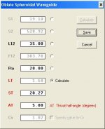
Hornresp can now calculate the construction data for an axisymmetric oblate spheroidal waveguide having a non-zero throat entry angle. The following example and screenprint demonstrate how the method would be applied to obtain the necessary dimensions for a 2 inch diameter, 5 degree half-angle throat entry on an OS waveguide having a fully-formed length of 35 cm and an asymptotic mouth flare tangent angle of 20 degrees.
Procedure:
1. Open the Horn Segment Wizard for an oblate spheroidal waveguide design.
2. Click on the option button alongside the LT (Throat offset length) text box.
3. Enter L12 = 35 cm, Fta = 20 degrees, ST (Throat entry area) = 20.27 sq cm, AT (Throat half-angle) = 5 degrees.
(Note that moving the mouse pointer over the LT, ST or AT text boxes displays an explanatory description of the variable).
4. Click on the ‘Calculate’ button, and then click on the ‘Save’ button.
5. Display the Schematic Diagram.
6. Select the File > Export menu command.
7. Save the data to a *.csv file.
8. Open the file in Excel and manipulate the data in the ‘Length (cm)’ and ‘Radius (cm)’ columns or plot the axisymmetric waveguide profile as desired. Progressive flare tangent angle data is given in the ‘Angle (Deg)’ column.
Note that only the exported data refers to an oblate spheroidal waveguide having a 2 inch diameter, 5 degree half-angle throat entry. The schematic diagram and calculated response results still apply to a fully-formed oblate spheroidal waveguide with zero degree throat entry.
The example oblate spheroidal waveguide with a 2 inch diameter, 5 degree half-angle throat entry is effectively a fully-formed oblate spheroidal waveguide having a 19.10 sq cm area throat, but with the throat end truncated by 1.68 cm (the throat offset length LT as calculated by the Horn Segment Wizard).
Although I have tested the new functionality quite thoroughly, there is always the possibility that something may have slipped through. If you come across any bugs please let me know.
Kind regards,
David
David McBean said:I will let you know when the update is released.
Hi Everyone,
Hornresp can now calculate the construction data for an axisymmetric oblate spheroidal waveguide having a non-zero throat entry angle. The following example and screenprint demonstrate how the method would be applied to obtain the necessary dimensions for a 2 inch diameter, 5 degree half-angle throat entry on an OS waveguide having a fully-formed length of 35 cm and an asymptotic mouth flare tangent angle of 20 degrees.
Procedure:
1. Open the Horn Segment Wizard for an oblate spheroidal waveguide design.
2. Click on the option button alongside the LT (Throat offset length) text box.
3. Enter L12 = 35 cm, Fta = 20 degrees, ST (Throat entry area) = 20.27 sq cm, AT (Throat half-angle) = 5 degrees.
(Note that moving the mouse pointer over the LT, ST or AT text boxes displays an explanatory description of the variable).
4. Click on the ‘Calculate’ button, and then click on the ‘Save’ button.
5. Display the Schematic Diagram.
6. Select the File > Export menu command.
7. Save the data to a *.csv file.
8. Open the file in Excel and manipulate the data in the ‘Length (cm)’ and ‘Radius (cm)’ columns or plot the axisymmetric waveguide profile as desired. Progressive flare tangent angle data is given in the ‘Angle (Deg)’ column.
Note that only the exported data refers to an oblate spheroidal waveguide having a 2 inch diameter, 5 degree half-angle throat entry. The schematic diagram and calculated response results still apply to a fully-formed oblate spheroidal waveguide with zero degree throat entry.
The example oblate spheroidal waveguide with a 2 inch diameter, 5 degree half-angle throat entry is effectively a fully-formed oblate spheroidal waveguide having a 19.10 sq cm area throat, but with the throat end truncated by 1.68 cm (the throat offset length LT as calculated by the Horn Segment Wizard).
Although I have tested the new functionality quite thoroughly, there is always the possibility that something may have slipped through. If you come across any bugs please let me know.
Kind regards,
David
Attachments
what is (or can possibly be) the advantage of "continuously changing cross-sectional shape" of a horn?
http://www.aes.org/e-lib/browse.cfm?elib=4926
best,
graaf
http://www.aes.org/e-lib/browse.cfm?elib=4926
best,
graaf
graaf said:what is (or can possibly be) the advantage of "continuously changing cross-sectional shape" of a horn?
http://www.aes.org/e-lib/browse.cfm?elib=4926
best,
graaf
Sounds like an advertisment to me.
Member
Joined 2003
I would suggest that your hypothesis is wrong. The diffraction will be the same no mater how close or far from the source it is. Diffraction depends only on the rate of change of the slope - in mathematical terms it is proportional to the second derivative of the contour. Thus the larger the radius the smaller the second derivative and the less the diffraction. There is no location dependence.
SPL decreasing with increasing distance from the driver has no effect on magnitude of the diffracted signal?
Paul W said:
SPL decreasing with increasing distance from the driver has no effect on magnitude of the diffracted signal?
As a fraction of the SPL the diffraction is constant, its linear, thus the diffraction level in SPL will decrease with distance since the SPL decreases, but the line along which the diffraction occurs (mouth circumference) is increasing. The SPL drops as r (r is the waveguide length) while the line length increases as r so that the diffraction SPL remains unchanged with increasing waveguide length. I think that you hypothesized that it would increase with length. The only thing that matters is the radius of the flare.
Would a shorter waveguide with a larger radius work better than a longer waveguide with a shorter radius. I'd guess not, but on this score I have no data. I would guess that you would trade off diffraction for directivity control - an interesting tradeoff that would take some experimenting to sort out in depth. Clearly its best to have a larger waveguide with a larger radius and I always attempt to use one as large as possible.
Member
Joined 2003
I think that you hypothesized that it would increase with length.
Actually I thought SPL would decrease with increased radial distance but didn't factor in the increasing circumferential line length.
In the coming months I plan to build some really large waveguides but want to get the best overall performance from a given OD and am trying to understand if there is a better mouth flare than a simple circular radius. Does "burning" OD with a larger radius early in the curve have a benefit over a circular radius? The simple radius is easiest to construct, but a more complex curve (large radius early, decreasing radius at the outer edge) doesn't add much difficulty.
Paul W said:
Does "burning" OD with a larger radius early in the curve have a benefit over a circular radius? The simple radius is easiest to construct, but a more complex curve (large radius early, decreasing radius at the outer edge) doesn't add much difficulty.
But I don't see where it adds any advantage. It sounds a little like you are suggesting an inverse OS which starts out with no curvature and then gets greater at a linear rate until it is flat. Perhaps this might have some small advantage, but I think that it would take more space to do. To me these would be small effects and the biggest advantage comes from just going bigger with a larger radius.
gedlee said:
Sounds like an advertisment to me.
an advertisment?! 😕
whose? of what?
of the AES convention paper?
Have You read the paper?
Member
Joined 2003
It sounds a little like you are suggesting an inverse OS which starts out with no curvature and then gets greater at a linear rate until it is flat.
I hadn't thought of it as an inverse OS but, yes, that would be a way to define the curve. Any downside to it when transitioning to a very large flat baffle?
Paul W said:
I hadn't thought of it as an inverse OS but, yes, that would be a way to define the curve. Any downside to it when transitioning to a very large flat baffle?
It takes a lot of space.
graaf said:
an advertisment?! 😕
whose? of what?
of the AES convention paper?
Have You read the paper?
You obviuosly haven't read many Japanese papers. They use forums like this to introduce new products.
Well, I just think that horn/guides will provide benefits over direct radiating drivers with the right design. Axisymmetric designs are pretty limited in design options. I would be quite dissapointed if that is the only way to get better performance. But I guess I won't know until I get into it a bit more. I will try to eleborate more on it when I have more analysis data. It was already a surpise to me to find voice coil structural resonances being a cause of some breakup modes, I'm sure I'll find more surprising things through analysis of horn/guides.gedlee said:
The question was specific: if I had considered using Jean-Michel's mouth and the answer is no, because I don't see an advantage. I DO see a potential advatange to varying the mouth radius with angle, and the Abbey+ may have that, but that is not what we were talking about. I DO NOT see an advantage in varying the radius in the radial direction (i.e still axisymmetric). They are vastly different things.
And would you care to ellaborate on "if the horn/guide mouth edge radius is varied in a certain way, mouth diffraction can be reduced". I don't see how this is possible - please explain.
soongsc said:
Well, I just think that horn/guides will provide benefits over direct radiating drivers with the right design. Axisymmetric designs are pretty limited in design options. I would be quite dissapointed if that is the only way to get better performance. But I guess I won't know until I get into it a bit more. I will try to eleborate more on it when I have more analysis data. It was already a surpise to me to find voice coil structural resonances being a cause of some breakup modes, I'm sure I'll find more surprising things through analysis of horn/guides.
Having studied hrons for almost 30 years I think that I have seen just about every conceivable variation. There are more tradeoffs with non-axisymetric ones than with axi-symmetric ones. You can, of course, go through all of the work yourself and start from scratch if you like, but the point of this post was to try and let you avoid all that by telling you ahead of time what works and what doesn't. But if you need to do it all yourself to be convinced, then by all means have a go.
Some things are like going to bed, I just have to do it myself.😀 It's alwayas good to know what others have experienced so that we can see if there is anything to be explored to make it better. That's where the excitement is.😀gedlee said:
Having studied hrons for almost 30 years I think that I have seen just about every conceivable variation. There are more tradeoffs with non-axisymetric ones than with axi-symmetric ones. You can, of course, go through all of the work yourself and start from scratch if you like, but the point of this post was to try and let you avoid all that by telling you ahead of time what works and what doesn't. But if you need to do it all yourself to be convinced, then by all means have a go.
- Home
- Loudspeakers
- Multi-Way
- Geddes on Waveguides