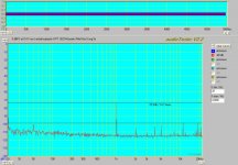
10 mW without filter:
The noise modulation is away, but high order spuriae from the generator appeared.
I am not sure if the methods shown much for my amps, one of them is class A and the second is class AB with EC. I guess the method would show more for traditional class B design, but I have no such amplifier at the moment.
Attachments

These measurements might discover one of the reasons of the neverending vinyl LP success. I believe it is the groove noise that makes it, by masking of low-level imperfections of the audio chain, and equalizing many systems to a similar level.
Actually all these measurements are interesting in that at the very least they show how hard it is to measure low level distortion accurately. Interesting how "dirty" both the generator (in terms of harmonics) and the active filter really are (noise floor modulation).
Also this somehow vindicates Earl Geddes' approach to generate a clean digital signal in the best possible way, including choosing a frequency that fits into the sampling window perfectly.
FWIW I tried some primitive loopback tests with my M-Audio USB pre, digital attenuation only. I get the noise floor down to close to -120 dB or so with averaging of a long FFT (0 dB for this sound card is at 0.4V, above this it is clipping pretty bad). But some high level harmonics remain practically constant regardless of input level. See attached the -80 dB measurement. There is no DUT here, just loopback. I'll have to check if it is the input or the output that is distorting.
Attachments
Yes, the loopback method always brings digital spuriae. Try to play both with output D/A and input A/D level to find optimum.
Also, calibrate the input level. I do it at 1Vrms = 0dB, so you can read what was the actual Vrms level at the card input. After simple maths, you see it fits to those 10mW/4ohm measurements.
Also, calibrate the input level. I do it at 1Vrms = 0dB, so you can read what was the actual Vrms level at the card input. After simple maths, you see it fits to those 10mW/4ohm measurements.
MBK said:Actually all these measurements are interesting in that at the very least they show how hard it is to measure low level distortion accurately. Interesting how "dirty" both the generator (in terms of harmonics) and the active filter really are (noise floor modulation).
There would be a chance, if I put another voltage divider behind output of the active filter. Then I could use higher amplitude from generator+filter and increase SNR of this combo. I hope to do it in future, not today 😉 . Anyway, it will probably bring no special discoveries, as both amps have very low distortion at low levels. But see that the class A PM-A1 is better in this comparison, it has nothing but 2nd harmonic measurable in 10mW - 1W range (and 50Hz + multiples residuals).
I played a lot with the in and out (analog) levels of the M-Audio, this is already the best combo I could come up with. I use -10 dB for out and 0 dB for in, beyond this I don't seem to gain anything.
The M-Audio Pre is a bit odd in that all in and outputs are AC coupled: both balanced and unbalanced in and outputs have no direct DC path to ground. Balanced operation results in some improvement of course, but for better or worse I can't use the proper method to connect unbalanced equipment, which would be to ground the "cold" lead at the input: the sleeves of the balanced in are not connected to ground either.
Calibration: the inputs have attenuators, but in front of these attenuators there must be some clamping diodes to prevent overload, because input >0.4V rms results in heavy harmonics even with attenuated signal. But yes, I could "calibrate" it by calculation, if not by applying actual 1V rms.
MBK said:But some high level harmonics remain practically constant regardless of input level. See attached the -80 dB measurement. There is no DUT here, just loopback. I'll have to check if it is the input or the output that is distorting.
Try to set sampling rate to 48khz, these artefacts looks much like resampling. (converting 48khz to 44.1khz)
Most soundcards always work at fixed 48khz.
Also try to not use digital attenuation, changing volume also creates artefacts.
See attachment what is possible with an internal pci-soundcard.
Mike
Attachments
MikeB said:With this setup (loop back) symasym (jfet version) measures like that: (~1w into 8ohm, much better than simulation predicted)
Hi Michael,
Great! Would you also try 10mW and 100mW, and also into 4ohm? Or dynamic range is not wide enough?
Regards,
Pavel
Edit: corrected, divider is needed for 1W (2.83Vrms)
Pavel, i will try that, but has to wait ~1 week, i am to busy with my work at the moment. It will be some work as i do not remember all parameters that were necessary.
Mike
Mike
janneman said:Hi guys,
Has anyone here experimented or experience with lock-in amplifiers to measure HD components?
Jan Didden
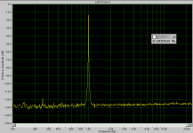
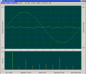
As I told before (post 125), I'm using a kind of software 'lock-in' combined with averaging a large number of cycles. Now I like to show some results. The first picture represents the noise floor and/or residual from a test signal of 5kHz. It is obtained just by subtracting the results from two identical runs.
The upper windows shows the fundamental and residual, while the lower window shows the spectrum (on a linear scale). The amplitude of the 2nd harm. = -1560dB and the 3rd = -144.9dB. The measurement bandwidth is 50kHz.
In the next post, you'll find the measurement results on a commercial amp.
Attachments
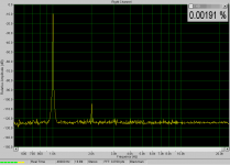
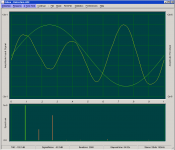
And here is the distortion of a NAD317 at 5kHz and Po=91mW
H2 = -109.9dB, H3 = -101.7dB and BW = 50kHz
This result is obtained by subtracting the residuals from two runs, one with the amplifier and one with the measurement setup alone.
Cheers, Edmond.
edit: No cross-over distortion is visible.
H2 = -109.9dB, H3 = -101.7dB and BW = 50kHz
This result is obtained by subtracting the residuals from two runs, one with the amplifier and one with the measurement setup alone.
Cheers, Edmond.
edit: No cross-over distortion is visible.
Attachments
Edmond Stuart said:... It is obtained just by subtracting the results from two identical runs.
I think you can't simply subtract the distortions unless you know the phasehifts of these distortions. Because of these phasehifts you don't know if the distortions from measuring and from amp add or subtract.
Especially even harmonics tend to cancelling.
Mike
MikeB said:I think you can't simply subtract the distortions unless you know the phasehifts of these distortions. Because of these phasehifts you don't know if the distortions from measuring and from amp add or subtract.
Especially even harmonics tend to cancelling.
Mike
Hi Mike,
Good point. Although I didn't mentioned it explicitly, I do apply a correction on the 'reference' distortion, based on the phase and frequency response of the DUT. It is a rather complicated affair, as in this case too, the phase and frequency response of the sound card has to be determined first, then a run with the DUT included and finally, subtract from this response the result of the first run.
Cheers, Edmond.
MikeB said:
Try to set sampling rate to 48khz, these artefacts looks much like resampling. (converting 48khz to 44.1khz)
Most soundcards always work at fixed 48khz.
Also try to not use digital attenuation, changing volume also creates artefacts.
Mike
I usually do use 48k for that reason; but yes, here I used digital att. which may be dirty, just to do a quick test to see how far this card will go in SNR.
In THD the card is maxed out btw. In fact technically it's a miracle: outputs are rated at -87 dB THD and inputs at -78 dB (!). Not good compared to contemporary internal cards, but the advantage of this card is its robustness (its intended purpose is as a mobile preamp for musicians to plug in whatever range of stuff instruments have).
Last time I used an internal soundcard for amp measurement, a transient (of Symasym no less!
 ) blew the inputs AND the controller board of the main harddisk (!). I forgot to unplug the card at switch on. Anyway for now I stay with the robust method ... but it means my Symasym channels at Watt level output just all measure similar to loopback...
Still if low level distortion is an issue it should be far above those -78 dB of my card, and I want to try this, just haven't had time yet to set up a proper measurement.
Mackie ONYX driver bug
Hi
Sadly had to realise that the Mackie ONYX 400F isn’t as good as I thought.
Trying to improve my loop back measurements in comparison to what others have shown here revealed that there is no way beyond 16 bit in harmonics.
Most likely this is due to a windows driver issue.
Above we see a comparison of the Mackie ONYX in loop back ( upper pic ) and a NTI MiniRator plugged ( lower pic ).
The MiniRator is a true 16 bit device what is reflected in the elevated noise floor. Harmonic distortion is basically the same in both measurements .
Both software ARATA and AudioTester indicate problems if I try to set the ONYX output to 24 bit .
Sorry, I will have to delay the low level amp measurements planned until Mackie is willing to fix that bug.
Greetings
Michael
Hi
Sadly had to realise that the Mackie ONYX 400F isn’t as good as I thought.
Trying to improve my loop back measurements in comparison to what others have shown here revealed that there is no way beyond 16 bit in harmonics.
Most likely this is due to a windows driver issue.
An externally hosted image should be here but it was not working when we last tested it.
An externally hosted image should be here but it was not working when we last tested it.
Above we see a comparison of the Mackie ONYX in loop back ( upper pic ) and a NTI MiniRator plugged ( lower pic ).
The MiniRator is a true 16 bit device what is reflected in the elevated noise floor. Harmonic distortion is basically the same in both measurements .
Both software ARATA and AudioTester indicate problems if I try to set the ONYX output to 24 bit .
Sorry, I will have to delay the low level amp measurements planned until Mackie is willing to fix that bug.
Greetings
Michael
Hi,
finally got it, how to obtain satisfying results with my ONYX sound card.
All plots were taken without any additional equipment. Setting all levels analogue to their best does the trick.
What can be seen here is that it is possible to get a reliable 110 dB dynamic range.
Note that the Y-axis is dB FS ( full scale ) not dBV !
What can be seen here is that it is possible to get reliable measurements down to roughly –140 dBV.
This is a stunning 1/10.000.000 V = 100 nV.
Note that this is only true with weak signals as dynamic range is less than 80 dB.
Greetings
Michael
finally got it, how to obtain satisfying results with my ONYX sound card.
All plots were taken without any additional equipment. Setting all levels analogue to their best does the trick.
An externally hosted image should be here but it was not working when we last tested it.
What can be seen here is that it is possible to get a reliable 110 dB dynamic range.
Note that the Y-axis is dB FS ( full scale ) not dBV !
An externally hosted image should be here but it was not working when we last tested it.
What can be seen here is that it is possible to get reliable measurements down to roughly –140 dBV.
This is a stunning 1/10.000.000 V = 100 nV.
Note that this is only true with weak signals as dynamic range is less than 80 dB.
Greetings
Michael
Hi,
Having solved the hurdles of proper measurement setup I now can compare to the measurements Earl did in posting #16
http://www.diyaudio.com/forums/attachment.php?s=&postid=1311718&stamp=1190930297
First DUT is a discrete build KENWOOD car amp
This one isn't supposed to be of finest quality but doesn't measure that bad.
Note that these kind of amps do have switched power supply.
Next DUT is a NAIM NAP 110 amp
These amps did set a standard at their time.
2nd harmonic same as KENWOOD and additional 1st harmonics at –10 dBV out.
Next DUT is a NAIM NAP 140 amp
This amp differs from the above NAP 110 ONLY in the power supply AFAIK.
Considerable less distortion but more PS noise than its predecessor.
Last DUT is a nice sounding MOSFET
Quite a mixed bag all in all, no?
As far as I can see these measurements meet the goal stated by Earl – provided that his Y-axis is meant to be dBV.
Crossover distortion at low signal levels isn't there at all.
Most obvious is the " noise " coming from the power supply I guess. No hum with the ear at the speaker though.
Any comments are very appreciated.
Greetings
Michael
Having solved the hurdles of proper measurement setup I now can compare to the measurements Earl did in posting #16
http://www.diyaudio.com/forums/attachment.php?s=&postid=1311718&stamp=1190930297
First DUT is a discrete build KENWOOD car amp
An externally hosted image should be here but it was not working when we last tested it.
This one isn't supposed to be of finest quality but doesn't measure that bad.
Note that these kind of amps do have switched power supply.
Next DUT is a NAIM NAP 110 amp
An externally hosted image should be here but it was not working when we last tested it.
These amps did set a standard at their time.
2nd harmonic same as KENWOOD and additional 1st harmonics at –10 dBV out.
Next DUT is a NAIM NAP 140 amp
An externally hosted image should be here but it was not working when we last tested it.
This amp differs from the above NAP 110 ONLY in the power supply AFAIK.
Considerable less distortion but more PS noise than its predecessor.
Last DUT is a nice sounding MOSFET
An externally hosted image should be here but it was not working when we last tested it.
Quite a mixed bag all in all, no?
As far as I can see these measurements meet the goal stated by Earl – provided that his Y-axis is meant to be dBV.
Crossover distortion at low signal levels isn't there at all.
Most obvious is the " noise " coming from the power supply I guess. No hum with the ear at the speaker though.
Any comments are very appreciated.
Greetings
Michael
- Status
- Not open for further replies.
- Home
- Amplifiers
- Solid State
- Geddes on distortion measurements