Some time back when I built my Soekris DAC I had Amanero and WaveIO USB->I2S options to try. So I tried both. I had similar problems with Amanero. I do not remember all details, but all in all I had issues getting reliable playback with ASIO and Amanero in 24/32bit modes. Same conditions with WavIO worked ok, so Amanero went back to storage and remains unused.
Before MI, I used ARTA software mainly.
Arta have the same problem if you can try the Amanero (ASIO) as Soundcard Driver.
Probably, this issue isn't from ARTA or MI but the asio issue to feed two devices at the same time.
I could find a solution about this with asio4all driver, in ARTA. I choose as Soundcard driver the asio4all and with control panel that there is in the ARTA window, I setup the input-output of the driver (input the RTX and output the Amanero).
With this the ARTA works perfectly!
The same thing I couldn't make with MI, because there is no any choice to setup via the MI DAC window.
Use separate PCs to verify😉Probably, this issue isn't from ARTA or MI but the asio issue to feed two devices at the same time.
Different ASIO drivers for ADC and DAC are supported even in the SAME instance of MI
@lemon,
Different ASIO drivers can be used for ADC and DAC in the SAME instance of MI from the official version 3.8.3.0 onwards (released after Sept. 1, 2018). Not sure whether you are still using the unofficial version released earlier than that or not. In the old version, you can check the minor version by right clicking the executables MIs.exe or MIu.exe. In the latest version 3.8.4.0 (released Nov. 21, 2018), you can also check the minor version through [help=>[About]. We have tested it with different ASIO sound cards and found no problem so far. We have not tested it with Amanero (ASIO), though. You can also try it with different MI instances in case you have already used the latest MI version.]%[/help]
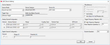
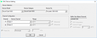
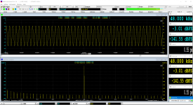
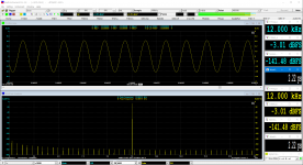
Here is an example of using different ASIO drivers in the same instance of MI.
ADC: an ART USB sound card
DAC: Focusrite USB sound card
If the same ASIO driver is used for both ADC and DAC, MI will interlock the sampling rates chosen for ADC and DAC.
If different ASIO drivers are used for ADC and DAC, MI will allow free selection of the sampling rates for ADC and DAC. In this example, 48kHz used for ADC and 192kHz used for DAC.
Attachments
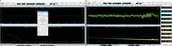
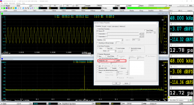
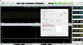
Here the new results.
I had installed 3.8.3.0 and now I upgrade to 3.8.4.0
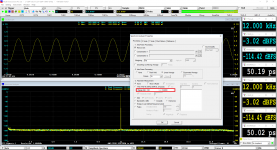
The first capture is with the amanero asio driver to the DAC Section, the next capture with asio4all.
Same behavior as before (3.8.3.0), with amanero driver there is burst oscilloscope capturing with asio4all nothing.
I done the testing with alone MI and with double running of MI, one for generator and the other for ADC only. Both of them have the same results.
I think the only solution is to make you enable the control panel at the DAC Section for the asio4all to make setup for input and output of this driver.
For example here the capture from another software Diana that enables the Control Panel of this driver and gives a nice solution to the same issues.
I had installed 3.8.3.0 and now I upgrade to 3.8.4.0
The first capture is with the amanero asio driver to the DAC Section, the next capture with asio4all.
Same behavior as before (3.8.3.0), with amanero driver there is burst oscilloscope capturing with asio4all nothing.
I done the testing with alone MI and with double running of MI, one for generator and the other for ADC only. Both of them have the same results.
I think the only solution is to make you enable the control panel at the DAC Section for the asio4all to make setup for input and output of this driver.
For example here the capture from another software Diana that enables the Control Panel of this driver and gives a nice solution to the same issues.
Attachments
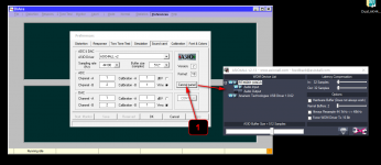
How to find ASIO4ALL Control Panel
So it is not a problem of multiple ASIO drivers in one software instance. It looks like a problem of Amanero ASIO driver itself?
When you use MI with the ASIO4ALL driver, you should be able to find the ASIO4ALL control panel at the lower right corner of the screen when the software is running, see the attached screenshot.
Attachments

Yes, it seems to be Amanero driver problem.
Just, I saw your small green icons of asio4all at the windows corner, I uninstalled and reinstalled the new version of this driver and the problem has gone.
Now, I have the small icon of control panel at the lower right corner of the screen when the software is running! 🙂
Now, I am OK with the MI software and I can to measure this dac via asio4all driver.
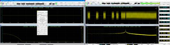
Virtins, can you help me how can I exact the right information about Jitter measurement?
I followed the directions at the page 260 of MI Manual (pdf).
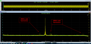
The sampling is 48K and of course the 1/4 of SR un-dithered sine wave will be 12.000123 KHz.
At the signal the MI adds the 1/192 of SR, low un-dithered square wave, i.e 250Hz.
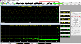
In 24 bit J-Test figure that I have enclosed, I look some peaks with 250Hz difference (look the measurement at the zoom jitter) that according to your document due by 250Hz square signal. There are some minus other peaks probably they are deterministic jitter but I can't see a clearly phase jitter.
The peak of the fundamental is to -27dB and the noise floor to -160dB, 133dB difference. The 250Hz peaks are at the 141-147dB zone almost 120-126dB difference from fundamental.
The documentation says that this leaves a good room for jitter measurement, without any additional information about this.
Is there something else that can help us to jitter measurement or this is a demonstration of Jitter figure only?
Just, I saw your small green icons of asio4all at the windows corner, I uninstalled and reinstalled the new version of this driver and the problem has gone.
Now, I have the small icon of control panel at the lower right corner of the screen when the software is running! 🙂
Now, I am OK with the MI software and I can to measure this dac via asio4all driver.
Virtins, can you help me how can I exact the right information about Jitter measurement?
I followed the directions at the page 260 of MI Manual (pdf).
The sampling is 48K and of course the 1/4 of SR un-dithered sine wave will be 12.000123 KHz.
At the signal the MI adds the 1/192 of SR, low un-dithered square wave, i.e 250Hz.
In 24 bit J-Test figure that I have enclosed, I look some peaks with 250Hz difference (look the measurement at the zoom jitter) that according to your document due by 250Hz square signal. There are some minus other peaks probably they are deterministic jitter but I can't see a clearly phase jitter.
The peak of the fundamental is to -27dB and the noise floor to -160dB, 133dB difference. The 250Hz peaks are at the 141-147dB zone almost 120-126dB difference from fundamental.
The documentation says that this leaves a good room for jitter measurement, without any additional information about this.
Is there something else that can help us to jitter measurement or this is a demonstration of Jitter figure only?
Attachments
Window function for J-TEST
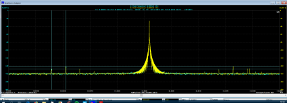
The wide skirt of the peak frequency in your screenshot looks like an artefact due to the wrong window function chosen rather than the result of jittering. It looks like a Hann skirt. Hann window is not suitable for this test due to its relatively high spectral leakage. It is advisable to always use software loopback to check first whether the designed settings are suitable for the designed measurement or not.
The attached three screenshots show the software loopback tests for the 24-bit J-TEST using Hann, Kaiser 6 and Kaiser 8 Windows respectively. It can be seen that in the range of 0 dBr~200 dBr, the spectral leakage skirt disappears only when Kaiser 8 (or above) window is used.
Attachments
Thanks for the info, Virtins.
What type of UDDP Definition you used for the JitterRMS_A/JitterRMS_B on DDP Viewer Configuration?
What type of Jitter is, is this total?
What type of UDDP Definition you used for the JitterRMS_A/JitterRMS_B on DDP Viewer Configuration?
What type of Jitter is, is this total?
Last edited:
Total RMS Jitter Level Calculation
Here are the 16-bit J-Test and 24-bit J-Test Panel Setting Files (PSF), compatible with MI 3.8.4.0 and above. It assumes that the sidebands and noises are caused by jitter only. The RMS jitter level in (picoseconds) can be determined by: R=20×log10(Jrms×f)-227dB, where R is the amplitude ratio (in dB) of the jitter frequency to the signal frequency, Jrms the RMS jitter level in picoseconds, and f the signal frequency in Hz.
The UDDP---JitterRMS_A is therefore defined as follows:
POW(10,(227-[f1RMS_A(EU)]+[NoiseLevel_A(EU)])/20)/[f1Freq_A(Hz)]
Where:
f1Freq_A(Hz)] is the DDP for the (peak) signal frequency (in Hz).
f1RMS_A(EU) is the DDP for the RMS of the (peak) signal frequency (in dB here)
NoiseLevel_A(EU) is the DDP for the RMS of the noise level (in dB here)
POW is the power function.
Using the above formula directly might cause overflow if the RMS ratio of signal to noise is not range-validated due to the power of 10 operation, when the test signal is not present. After adding the range validation, the UDDP definition becomes:
IFGT([f1RMS_A(EU)]-[NoiseLevel_A(EU)],10,POW(10,(227-[f1RMS_A(EU)]+[NoiseLevel_A(EU)])/20)/[f1Freq_A(Hz)],-1)
That is, if the signal level exceeds the noise level by 10 dB, calculate the RMS jitter level, otherwise returns -1.
The following screenshot shows the residual total RMS jitter level of the 24-bit JTEST signal itself calculated using the above method.
Attachments

Wonderful!
Thank you so much, Virtins.
Here are three jitter captures.
The first is a 48KHz J-Test like yours, with jitter 2.22ps
The second is a 192KHz with jitter 0.55ps with the same conditions.
The third is RTX6001 loopback (DAC SE->ADC) capture at 192KHz, the jitter is 25.15ps for left and 25.21 for the right channel.
From what I can understand:
1) as the sampling increase, decrease the jitter of the RTX
2) the first two captures are internal measurements without DAC involved.
3) the third capture is the DAC jitter capability at the 192KHz, of course the jitter will be increased at lower sampling (i.e 99ps@48KHz)
4) at the third capture the square wave contribution doesen't seems because this "covered" from the rising of Noise Level (-115dBFS)?
Attachments
Virtins, Does MI have inbuilt panels to perform a linearity test on a DAC? This test would sweep digital input level from 0 dBFs to -130 dBFs and track output amplitude with expected value. Many thanks.
Jitter is typically given with audio bandwidth weighting (20 Hz to 20 kHz). This would also reduce the 2.2 ps jitter in the self-test significantly, as the respective noise level of -141 dBFS is mainly caused by the lowest frequency signal part (below 20 Hz).
So could you gift us another version of JTest-PSF with said audio bandpass active?
Also I am a bit astonished that at quad rate the jitter value goes down. That is not logical and points to a calculation error. But maybe that behaviour also vanishes with the audio bandpass weighting...
So could you gift us another version of JTest-PSF with said audio bandpass active?
Also I am a bit astonished that at quad rate the jitter value goes down. That is not logical and points to a calculation error. But maybe that behaviour also vanishes with the audio bandpass weighting...
Yes, it is very strange that the jitter measurement is better with high sampling vs lower sampling.
Usually, the opposite is normal.
I didn't know that the jitter measurement is to 20-20KHz band only! But if it is true, what happening with 192KHz sampling that the fundamental will be at the 48KHz?
I will wait the Virtins' answer for all that.
Usually, the opposite is normal.
I didn't know that the jitter measurement is to 20-20KHz band only! But if it is true, what happening with 192KHz sampling that the fundamental will be at the 48KHz?
I will wait the Virtins' answer for all that.
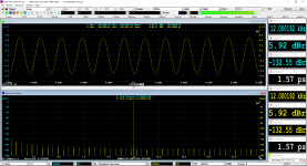
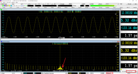
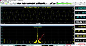
Yes, the noise level calculation bandwidth in the J-Test configuration files provided in Post #491 was set to 20Hz~24kHz. Thus they can be used for a sampling rate below or equal to 48kHz only. Attached are the updated J-Test PSFs, the noise level calculation bandwidth has been changed to 20Hz~768kHz, so they can be used for a sampling rate up to 1536 kHz. When integrating the noise spectrum from the lower limit to the upper limit, the software will automatically stop at half of the selected sampling rate if the upper limit is higher than that. Therefore setting the upper limit to 768kHz will be quite universal. You can also change this bandwidth by right click anywhere within the spectrum analyzer window and select [Spectrum Analyzer Processing]>[Parameter Measurement]>”Range (Hz)” (as shown in the attached pictures).
RTX6001 has a quite flat noise level from 20Hz to 96kHz. When the sampling rate is 192kHz, if the noise level calculation bandwidth is changed from 20Hz~24kHz (Picture 1) to 20Hz~96kHz (Picture 2), the noise energy will be quadrupled (increased by 6.02 dB), and the RMS noise amplitude will be doubled. Thus the RMS jitter level will be doubled (see formula in Post #491). When the sampling rate is 48kHz (Picture 3), the noise level is almost the same as that of Picture 1, but the test frequency is only ¼ of that of Picture 1, therefore, the RMS jitter level is quadrupled. It should be noted that the RMS jitter level calculation here is based on the assumption that all the noises are caused by the jitter only which may not be true. On the other hand, the real jitter may not even show up in the spectrum as RTX6001 uses the same sampling clock for ADC and DAC.
The above noise calculation bandwidth change has a minimum impact on the software loopback tests as the noise (sideband) energy is concentrated at the lower frequency end (the fundamental frequency of the 1/192 sampling rate, 1 LSB square wave is the highest side bands).
By the way, why should the RMS jitter level in seconds be higher at higher sampling rate which has a lower period in seconds?
Attachments
@douggoldberg
The DAC “THD vs Output Level in dBFS” test can be done through the Device Test Plan in MI. The output is specified in dBFS and thus can be preconfigured without switching the output gain switch by the software. However, if RTX6001 is used as the measurement ADC, there is a need to switch the input gain switch by the software in order to achieve the optimum measurement accuracy. Without prior knowledge of the output voltage range of the DAC, some sort of autoranging algorithm needs to be built inside the steps of the Device Test Plan. If the above understanding is correct, the Device Test Plan will be provided shortly.
The DAC “THD vs Output Level in dBFS” test can be done through the Device Test Plan in MI. The output is specified in dBFS and thus can be preconfigured without switching the output gain switch by the software. However, if RTX6001 is used as the measurement ADC, there is a need to switch the input gain switch by the software in order to achieve the optimum measurement accuracy. Without prior knowledge of the output voltage range of the DAC, some sort of autoranging algorithm needs to be built inside the steps of the Device Test Plan. If the above understanding is correct, the Device Test Plan will be provided shortly.
Thanks Virtins. I tried a bit and think you just opened a can of worms.
The only other two systems that give jitter values in ps that I know of are Miller Audio Research and the Audio Precision. And it seems as if their 'picoseconds' are very different to your 'picoseconds'. For example the Miller measures the 16 bit JD test signal at around 120 ps, but that is peak to peak! Using the above new J-Test psf at 44.1 kHz, your MI measures them at around 620 ps rms, which equals a whopping 1753 picoseconds (digital to digital test, bit-perfect). Further reading finds that the Miller unit explicitely searched for symmetrical sidebands, not taking all the noise into account. I don't know how the latest APx555 measures jitter in ps in detail, maybe someone here can share some information, especially which value the JD test signal itself will produce in 16 and 24 bit.
Also the lower limit of 2.21 ps with the 48 kHz 24 bit test signal, perfectly transmitted digitally (zero jitter), seems questionable. It should be 0...
- Home
- Group Buys
- GB for Virtins MI Pro for RTX6001 autoranging/autoscaling & for soundcard end users