At the J-Test 16bit is that properly to set the ADC to 16bit or 24bit?
The following result was came with Altor JG-384 signal generator as the role to source, set to 48KHz J-Test 16bit (12KHz/0.25KHz) @ 0dB mode and the connection was the DAC via the Optical SPDIF connection.
The analogue output of the DAC input to the RTX ADC and the capturing was to 16bit and 24bit.
I see at the 24bit ADC capture due to lower noise floor that the residues peaks are more "true" to measuring.
Is that some kind of trick that helping to us or it was a lucky moment?
Attachments
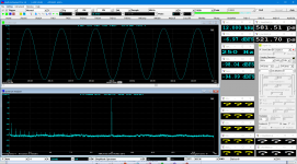

The lower noise floor from the 24 bit capture does show more details. I see no clear jitter artifacts in that plot. Certainly nothing to justify a 400 pS jitter measurement.
A 24 bit test from the Altor won't show the LSB on any DAC I have encountered. The LSB is below the noise floor on all of them. The Altor is a great tool. I recently used it to make some test files that I had confidence in.
A 24 bit test from the Altor won't show the LSB on any DAC I have encountered. The LSB is below the noise floor on all of them. The Altor is a great tool. I recently used it to make some test files that I had confidence in.
I have a problem with a compensation file yet, with the fcf type...I have done a try with a CSV file via excel but is not recognized from MI software.
I am looking how to change a csv to fcf type.
Normally I use Notepad to edit the FCF file. I just tried EXCEL and found no problem. After saving it as a CSV file in EXCEL, you will need to rename it from a CSV file to a FCF file in order for it to show up as a FCF file. Or else, change the "files of type" of the file open dialog box to "All files (*.*)" when you select a frequency compensation file in MI. Also, this file must be an ASCII text file not a Unicode one.
There are a few sample FCF files in the subdirectory "\fcf" of the software. It would be easier to modify from there.
But, I think that it could be nice to the future to setup a range that you want to find the MI software the peaks, without this to be a general compensation file to all sampling area.
Thanks for the suggestion. It will be considered in future releases.
I don't understand this...how this works? An example with real music, perhaps?
As the carriers is a sinewave. so it can generate a sinewave with jitter only. 🙂
wow and flutter removal
Capstan is the top end single ended solution $3500
Celemony | Capstan
this one is reputed to work, but requires more control from you (and its free)
Free Wow & Flutter Removal - pyrespeeder
and of course if you want there is the Plagant process that actively demodulates the signal based on the recorded bias signal.
Plangent Processes - the finest tape playback on the planet
Cheers
Alan
...
A 24 bit test from the Altor won't show the LSB on any DAC I have encountered. The LSB is below the noise floor on all of them. The Altor is a great tool. I recently used it to make some test files that I had confidence in.
Yes Demian, the Altor's gen is a great equipment but I would like some more improvement and minor corrections of its functions.
Normally I use Notepad to edit the FCF file. I just tried EXCEL and found no problem. After saving it as a CSV file in EXCEL, you will need to rename it from a CSV file to a FCF file in order for it to show up as a FCF file. Or else, change the "files of type" of the file open dialog box to "All files (*.*)" when you select a frequency compensation file in MI. Also, this file must be an ASCII text file not a Unicode one.
There are a few sample FCF files in the subdirectory "\fcf" of the software. It would be easier to modify from there.
- Nice, I followed your directions and everything go well now. Thanks.
I was looking again your #507 post and the page 134 "Sampling Jitter Transfer Function" of the AP link document, that you gave to us.
This testing can be done and with our MI sw, probably with manually steps.
At a table that the Y-axis has the amplitude of each measuring lower sideband and the X-axis all these Frequencies that jitter applied.
I don't know if this procedure can be to complete under DUT (probably with manually steps) but some of known Jitter and linearity tests (DAC), must be included to next versions.
I have a popup window (Miu) error at the starting.
The message is "Fail to start DAQ"
Is there a suggestion about this or must to reinstall the sw?
The message is "Fail to start DAQ"
Is there a suggestion about this or must to reinstall the sw?
I re-installed the software and the problems has gone.
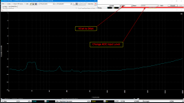
I need to change the parameters of the Crosstalk vs Frequency Test.
Look at the attachment:
1) from 16bit to 24bit
2) another ADC Input Level
I looked inside the "Crosstalk_vs_Frequency" dtp file with notebook, but only the way to change the resolution and output can find.
I need to change the parameters of the Crosstalk vs Frequency Test.
Look at the attachment:
1) from 16bit to 24bit
2) another ADC Input Level
I looked inside the "Crosstalk_vs_Frequency" dtp file with notebook, but only the way to change the resolution and output can find.
Attachments
For anyone that interesting about it, here the information about it.
At the /dtp folder, there are all the DUT tests, here is located the Crosstalk_vs_Frequency.dtp file.
At the first lines of this file, there a path for appropriate .psf file for this testing, note the path.
At the /psf folder, locate the above .psf file that Crosstalk_vs_Frequency.dtp opens.
Open this file via MI software and do the appropriate changes that you want (level, bit, e.t.c), then save it with the a new name.
Then open the Crosstalk_vs_Frequency.dtp file with notepad or another text software and change the path of .psf file with the new one.
That's all
With same way, you could to change and the others .dtp files like Crosstalk e.t.c
Happy new year to all !
@lemon, sorry for the late reply. It looks like that you have already figured out everything by yourself. Great!🙂. Just to add, the current crosstalk_vs_Frequency.dtp uses numbers to specify each test frequency explicitly. For example, for 100 test frequencies, 100 steps are required. If you want to customize the test frequencies, you do not need to configure it one by one. The software allows you to configure multiple similar test steps in one shot (see Section 8.2.6 Multi-Step Generation in the software manual). Another method is to use variables x1~x5 to specify the test frequency implicitly. The previous power supply output impedance test is such an example.
@lemon, sorry for the late reply. It looks like that you have already figured out everything by yourself. Great!🙂. Just to add, the current crosstalk_vs_Frequency.dtp uses numbers to specify each test frequency explicitly. For example, for 100 test frequencies, 100 steps are required. If you want to customize the test frequencies, you do not need to configure it one by one. The software allows you to configure multiple similar test steps in one shot (see Section 8.2.6 Multi-Step Generation in the software manual). Another method is to use variables x1~x5 to specify the test frequency implicitly. The previous power supply output impedance test is such an example.
I was looking again your #507 post and the page 134 "Sampling Jitter Transfer Function" of the AP link document, that you gave to us.
This testing can be done and with our MI sw, probably with manually steps.
At a table that the Y-axis has the amplitude of each measuring lower sideband and the X-axis all these Frequencies that jitter applied.
I don't know if this procedure can be to complete under DUT (probably with manually steps) but some of known Jitter and linearity tests (DAC), must be included to next versions.
I am not so clear about what you mean?
Hi Alan,
Sure, I'd like either channel alone on the screen, or both if desired. Right now I can only have channel 1 or both on.
-Chris
The latest version 3.8.5.1 (released on Dec. 31, 2018) has incorporated this suggestion. If you right click the Oscilloscope, Spectrum Analyzer or Spectrum 3D Plot, you can select [Display Ch. A only], [Display Ch. B only] or [Display All], if both input channels "A&B" are sampled.
Happy New Year to all, also!
Virtins, thanks for the suggestion.
I am off for a couple of days and I am away from my RTX+MI to looking about jitter test.
I'll come back, soon...
Virtins, thanks for the suggestion.
I am off for a couple of days and I am away from my RTX+MI to looking about jitter test.
I'll come back, soon...
The latest version 3.8.5.1 has incorporated this suggestion. To add a title to the X-Y Plot, right click it and select [X-Y Plot Chart Option]>"Title".I think will be good to have the ability to put a Title and subtitle to the X-Y Plot (perhaps to next VI-Pro version).
Hi VIRTINS,
Cool, I'll upgrade my software now in that case. Many thanks!!!
Happy New Year to you all. May this coming year be a very good one for you.
-Chris
Cool, I'll upgrade my software now in that case. Many thanks!!!
Happy New Year to you all. May this coming year be a very good one for you.
-Chris
Virtins, Does MI have inbuilt panels to perform a linearity test on a DAC? This test would sweep digital input level from 0 dBFs to -130 dBFs and track output amplitude with expected value. Many thanks.
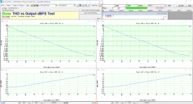
The function "THD vs output dBFS" and "Output dBV vs Output dBFS" is now available in V3.8.5.2. You can load the Device Test Plan named "THD_vs_OutputdBFS_RTX6001.dtp" to perform the test. It can be used to measure a DAC using RTX6001's ADC. This device test plan is configured using variables and is able to perform RTX6001 input autoranging based on -3 dB criterion. The step from -130dBFS to 0dBFS output is also configured as 3 dB. There are only 20+ test steps in total. So these parameters can be easily found and modified.
Please note that in this test plan:
1. [Setting]>[ADC Device]>"Device Model" should be set to "RTX6001 ASIO" or "RTX6001 MME".
2. [Setting]>[DAC Device]>"Device Model" should be set to "Sound Card ASIO" or "Sound Card MME" and the DAC under test should be selected in "Device No." selection box.
3. [Setting]>[Calibration]>"Sound Card Output Calibration Factor">"Range (V)" should remains as "±1V" (the default value). It is used as the 0 dBFS reference in this test plan.
The following is the test result of RTX6001's own DAC @20dBV. (It was switched to the 20dBV gain setting when [Setting]>[DAC Device]>"Device Model" = "RTX6001 ASIO". After that, let [Setting]>[DAC Device]>"Device Model" = "Sound Card ASIO" and "Device No." = "RTX ASIO Driver"). During this test, the input range of RTX6001 will automatically changed from ±141.4mV to ±44.72V as the output dBFS steps up from -130dBFS to 0dBFS.
Attachments
The latest version 3.8.5.1 (released on Dec. 31, 2018) has incorporated this suggestion. If you right click the Oscilloscope, Spectrum Analyzer or Spectrum 3D Plot, you can select [Display Ch. A only], [Display Ch. B only] or [Display All], if both input channels "A&B" are sampled.
The channel ref curve should have been excluded from that option - it has its own configuration dialog anyway. The way it works now the ref curve is also no longer displayed. That's a unnecessary and not helpful limitation.
The function "THD vs output dBFS" and "Output dBV vs Output dBFS" is now available in V3.8.5.2. .
Would it be easy to change the vertical scaling for distortion to dBR, or mabe both dBR and percentage? When the zeros start multiplying the numbers become hard to work with.
The channel ref curve should have been excluded from that option - it has its own configuration dialog anyway. The way it works now the ref curve is also no longer displayed. That's a unnecessary and not helpful limitation.
Ch. A and Ch. B have their own reference curves. The reference curves will be zoomed in/out and moved up/down with their own channel. When a channel is hidden, its reference curves are also hidden.
In some special cases, the user may want to display the real-time curve in a channel and its reference curve in another channel in order to be able to adjust the vertical screen offset between the two curves. In this case, both channels need to be displayed. It is possible to hide the real- time curve in the reference channel by setting its color to background color via [Setting]>[Display].
- Home
- Group Buys
- GB for Virtins MI Pro for RTX6001 autoranging/autoscaling & for soundcard end users