I would like 1 board if available.
Thank You
OK, now we have five boards with mine two:
malwin_____ 1 board
dobbo______ 1 board
zrxshack____1 board
Damir
I have one ????
malwin_____ 1 board
dobbo______ 1 board
zrxshack____1 board
platon.rado-----1 board
I have one ????
malwin_____ 1 board
dobbo______ 1 board
zrxshack____1 board
platon.rado-----1 board
Damir
I have one ????
malwin_____ 1 board
dobbo______ 1 board
zrxshack____1 board
platon.rado-----1 board
Sorry Radoslav, I ordered five and I need two boards for me. As there was no more interest I placed my order and paid it yesterday.
OK, now we have five boards with mine two:
malwin_____ 1 board
dobbo______ 1 board
zrxshack____1 board
The boards are here in Zagreb, I will receive them in monday.
Above is list, please send me PM with your PayPal email address and destination country and I will send PayPal request for money.
Damir

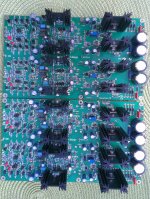
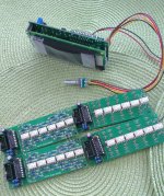
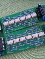
My balanced version with relays volume controller and inputs selector is slowly being assembled.
Attachments
Dadod,
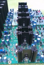
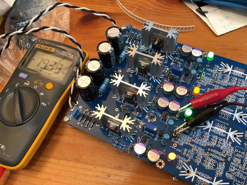
I just built the Shunt Regulator portion of the GW Mk3. I substituted the 8.6v zeners with 9.1v - hope that is not the problem. I only have one of the +ve rails working where the voltage adjusts and I can feel heat burning off on the heatsink. The others are pegged at -19.36v and +18.35v no adjustment possible and no heat from the shunting. Could I have some bad MOSFETs. I added some LED's to show power on each rail. I am also running 0.22R vs 0.1R near the outputs. Otherwise, I am following the specified parts. So where to debug?
I just built the Shunt Regulator portion of the GW Mk3. I substituted the 8.6v zeners with 9.1v - hope that is not the problem. I only have one of the +ve rails working where the voltage adjusts and I can feel heat burning off on the heatsink. The others are pegged at -19.36v and +18.35v no adjustment possible and no heat from the shunting. Could I have some bad MOSFETs. I added some LED's to show power on each rail. I am also running 0.22R vs 0.1R near the outputs. Otherwise, I am following the specified parts. So where to debug?
Attachments
My balanced version with relays volume controller and inputs selector is slowly being assembled.
What is this volume controller?
Dadod,
I just built the Shunt Regulator portion of the GW Mk3. I substituted the 8.6v zeners with 9.1v - hope that is not the problem. I only have one of the +ve rails working where the voltage adjusts and I can feel heat burning off on the heatsink. The others are pegged at -19.36v and +18.35v no adjustment possible and no heat from the shunting. Could I have some bad MOSFETs. I added some LED's to show power on each rail. I am also running 0.22R vs 0.1R near the outputs. Otherwise, I am following the specified parts. So where to debug?
Hi xrk971,
Your heat sink looks to small. A shunt regulator without load will dissipate all power, in this case between 3 and 4 W, depends of DN2540 CC current.
When load connected, in this case preamp part, it will take part of power dissipation, about 1.5 W and the shunt regulator will dissipate less.
Zener of 9.1 V is OK.
Regarding non working side, check all diodes orientation and soldering on back side. Check the mosfets too.
BR Damir
Attachments
- Home
- Amplifiers
- Solid State
- GainWire Mk3 CFA pre/phone amp with very low distortion