Hi xrk971,
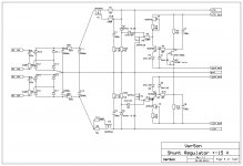
Your heat sink looks to small. A shunt regulator without load will dissipate all power, in this case between 3 and 4 W, depends of DN2540 CC current.
When load connected, in this case preamp part, it will take part of power dissipation, about 1.5 W and the shunt regulator will dissipate less.
Zener of 9.1 V is OK.
Regarding non working side, check all diodes orientation and soldering on back side. Check the mosfets too.
BR Damir
Ok, I will check diodes - orientation looks good, I wonder if some may be bad. Only way to check MOSFETs is to pull them out though or is there an easier way?
How does a single trimpot adjust both +ve and -ve voltage rail settings? Or does it move both simultaneously?
The heatsinks are warm, at zero load but not overly hot - I can touch it for more than 10 seconds so I think I may be ok.
If you take a look schematic you can see that the single trimpot sets both sides J1 CCS, it's just simple as this.
Check also for some cold or missing soldering.
Attachments
I pulled all the MOSFETs off the shunt reg and all the DN2540's are shot. They measure between 1.4kohm to 150kohm between G and D or G and S. Should be infinity, correct? All the IRF610 and 9610's are fine. The transistor tester also showed the DN's are bad. These are good ones that I got from Digikey so not sure how they got burned out so easily. I wear antistatic straps while working on the board the whole time.
These are good ones that I got from Digikey so not sure how they got burned out so easily.
How about the possibility of them getting too hot from using sinks that may be too small?
They never got hot - when I first turned it on 3 of 4 just conducted to full rail so no voltage drop happening and no heat. The one rail (+15v) on one side that did work never got unreasonably hot - especially since I backed off the regulation to make 18v the drop from 19.3v was minimal.
Remember that DN2540's are depletion mode - normally on with no gate applied. So when they fail, they fail in full on and have essentially no voltage drop to cause heating.
Remember that DN2540's are depletion mode - normally on with no gate applied. So when they fail, they fail in full on and have essentially no voltage drop to cause heating.
They never got hot - when I first turned it on 3 of 4 just conducted to full rail so no voltage drop happening and no heat. The one rail (+15v) on one side that did work never got unreasonably hot - especially since I backed off the regulation to make 18v the drop from 19.3v was minimal.
Remember that DN2540's are depletion mode - normally on with no gate applied. So when they fail, they fail in full on and have essentially no voltage drop to cause heating.
I am not sure what happened to DN2540, I never had any problem with them. DN2540 needs the voltage to work properly as a CCS. Input voltage should be 20 - 21 V, with 5 V drop on the DN2540 CCS to get working 15 V. You have to check if J1 CCS is working, changing trimpot value, should change the voltage on that CCS. Remember that both shunt regulators layouts are identical, and you can compare with the working one.
I'm building this v3 of this preamp even the v2 already working great.
I have a question:
Why you biased Q11 + Q12 with 2mA but biased Q15 + q16 to only about 1.3mA ?
I have a question:
Why you biased Q11 + Q12 with 2mA but biased Q15 + q16 to only about 1.3mA ?
I'm building this v3 of this preamp even the v2 already working great.
I have a question:
Why you biased Q11 + Q12 with 2mA but biased Q15 + q16 to only about 1.3mA ?
Why do you compare input super pairs biasing with output buffer biasing? It's quite important that output buffer load the current conveyor as low as possible (in the way of non linear impedance - capacitance).
You are free to simulate it and maybe find better bias.
Why do you compare input super pairs biasing with output buffer biasing? It's quite important that output buffer load the current conveyor as low as possible (in the way of non linear impedance - capacitance).
You are free to simulate it and maybe find better bias.
Thanks! I got the reason in your replied. Sorry if my question offend you in any way. I just got in DIY world and there are lot of things that I dont understand.
Thanks! I got the reason in your replied. Sorry if my question offend you in any way. I just got in DIY world and there are lot of things that I dont understand.
No offend what's ever. I would like opinions how to improve it, that's why I suggested simulation. By the way I don't understand many things regarding electronics (and much more in other arias too) that is why we are here to learn some more even in old are as I am, and that keeps the soul young.
Hi Damir,
Could I use 10R for all 22R resistors in the pre amp? I'm lacking 22R but have a lot of 10R in parts bin.
Could I use 10R for all 22R resistors in the pre amp? I'm lacking 22R but have a lot of 10R in parts bin.
Hi Damir,
Could I use 10R for all 22R resistors in the pre amp? I'm lacking 22R but have a lot of 10R in parts bin.
I suppose you can, it should not make significant differences.
I suppose you can, it should not make significant differences.
Thanks! I did the soldering work. I have another question:
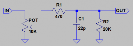
I use a separate volume 10K for the pre. So I cant connect it direct like in your schematic. I attached what I plan to use, do you think it is ok? R2 value = 20K seem ok? Or 10K is better?
Attachments
Last edited:
Thanks! I did the soldering work. I have another question:
I use a separate volume 10K for the pre. So I cant connect it direct like in your schematic. I attached what I plan to use, do you think it is ok? R2 value = 20K seem ok? Or 10K is better?
I am not sure what you mean "separate volume". If you look at mk3 layout there are connections for the outside board potentiometer which you can call separate.
On the mk3 schematic there is R29 47k resistor, and if you want to change it to 20 k that's OK.
One important thing, don't put low pass (LP) filter after the pot, its high frequency corner will change with the pot position. Put it before as in my schematic (22pF sims to low value).
I mean my volume pot is in separate box. It is LDR volume with Arduino controller so I cant put it together with the GainWire mkIII in the same chassis.
I checked and my listen spot is about 7K / 3K of the volume so I use the 22pf cap as LF filter. And since the pot no longer parallel with 47K resistor, I think I must lower it?
I checked and my listen spot is about 7K / 3K of the volume so I use the 22pf cap as LF filter. And since the pot no longer parallel with 47K resistor, I think I must lower it?
I mean my volume pot is in separate box. It is LDR volume with Arduino controller so I cant put it together with the GainWire mkIII in the same chassis.
I checked and my listen spot is about 7K / 3K of the volume so I use the 22pf cap as LF filter. And since the pot no longer parallel with 47K resistor, I think I must lower it?
Why it's not in parallel with 47k resistor, I see it still in parallel, just change R29 to 20 k if that suite you better.
I suggest to put LP filer before the volume.
By the way, have you made your own layout and board?
Why it's not in parallel with 47k resistor, I see it still in parallel, just change R29 to 20 k if that suite you better.
I suggest to put LP filer before the volume.
By the way, have you made your own layout and board?
Uhm. May be I think I can put the LF filter in the volume box and can forget that part in the preamp.
And yes. I drew the PCB layout for my personal usage. It took me months to finished that layout. I made it as dual mono.
Last edited:
Uhm. May be I think I can put the LF filter in the volume box and can forget that part in the preamp.
And yes. I drew the PCB layout for my personal usage. It took me months to finished that layout. I made it as dual mono.
Could you show it here, just the layout not the gerber?
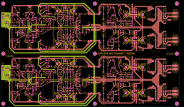
Sure, here is it ...
Nice, so you actually used my layout as a template?
Is it working already?
- Home
- Amplifiers
- Solid State
- GainWire Mk3 CFA pre/phone amp with very low distortion