I pulled out the 2SK170 from the top +ve rail and it tested it and it was dead. So was the 2N5485. I did not have anymore 2N5485's so replaced with a 2SJ113 and replaced the 2SK170BL. The top has adjustable voltage now. I decided to change out all the 2N5485's with 2SJ113 so at least they are all consistent. Both +ve supplies shunt regulate to 15.0v well now. However, nothing happens on the negative rails when the trimpot is adjusted. Is the negative rail supposed to be a mirror voltage compared to the postive rail? Why does it not have its own pot?
I went in and pulled out all the BC550 and BC560's in the PSU (they tested fine) but replaced them with fresh ones (also tested prior to installation).
I used a diode tester on all 1N4148's and the 8.2v zeners - they all show typical 0.56v forward voltage drop as a diode should. Their orientations are all correct.
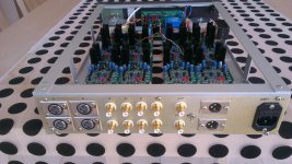
Here is a closeup photo. For 75R resistors, I paralleled two 150R's. For 7k5 I paralleled two 15k's.
So at this point, the positive rails are responsive to pot adjustments. The negative rails just sit at -19.5v and no heat is generated in the MOSFET heatsinks - so no shunting is happening. On postive rails, the MOSFETs are shunting and it is warm but not hot.
Also, in case you are wondering about the tabs on MOSFETs and heatsinks, I am using silicone insulator pads and insulating shoulder washers on bolts and nuts clamping the MOSFETs to the heatsink. I used continuity checker to makes sure none of the tabs are electrically connected to the bolts or heatsinks.
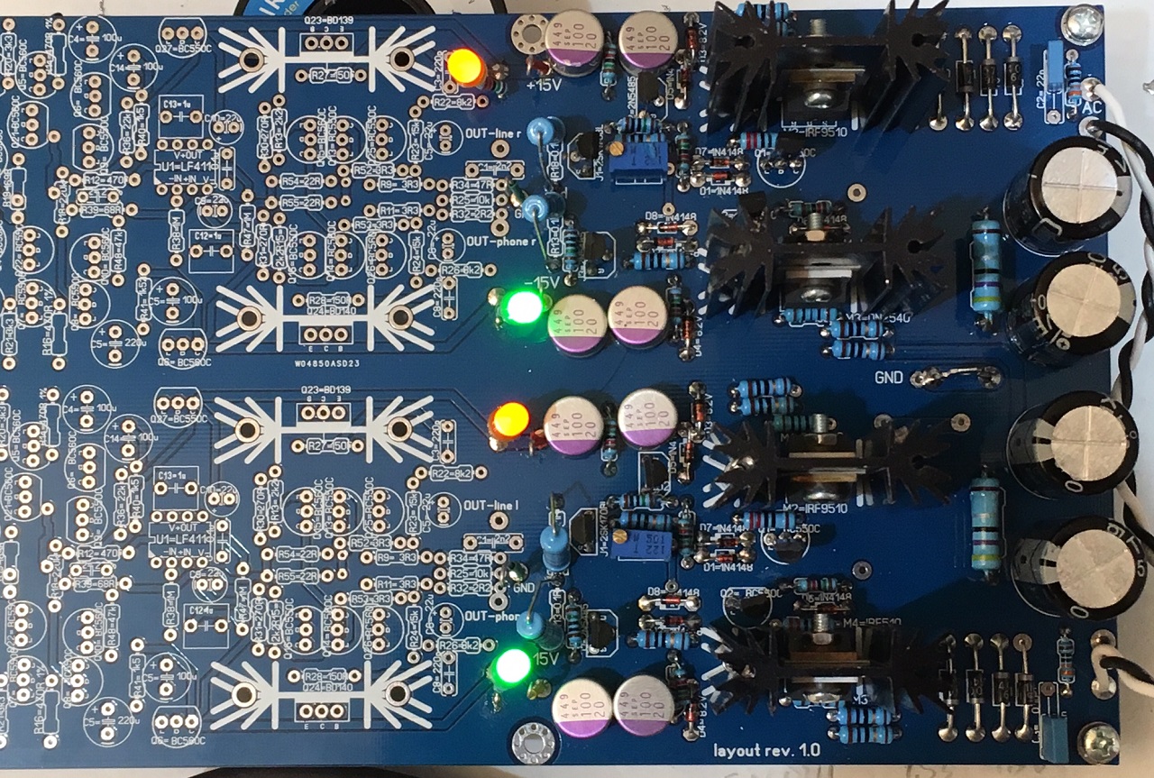
The photo is not very clear, but it looks that D8 is up side down on both channels.
Indeed it is reveresed! I missed that silkscreen error note!
Thanks!
Will flip those and give it a try now. Maybe we can move forward off of the PSU finally.
Edit: ok that fixed it! 🙂
Thanks for catching that. Ok can move on to the actual amp now.
Thanks!
Will flip those and give it a try now. Maybe we can move forward off of the PSU finally.
Edit: ok that fixed it! 🙂
Thanks for catching that. Ok can move on to the actual amp now.
Last edited:
Is it ok to run this amp at +/-18v? That would reduce dissipation on the shunts and give more headroom on the output.
Indeed it is reveresed! I missed that silkscreen error note!
Thanks!
Will flip those and give it a try now. Maybe we can move forward off of the PSU finally.
Edit: ok that fixed it! 🙂
Thanks for catching that. Ok can move on to the actual amp now.
That was my mistake, I forgot to put the link to that silkscreen error in first post. This is valid for first PCB order, second order had it corrected.
Is it ok to run this amp at +/-18v? That would reduce dissipation on the shunts and give more headroom on the output.
No, you need some headroom(voltages) for DN2540 to work properly as a current source.
Without preamp part all dissipation is spent on shunt elements (IRFs), when you install the preamp part it will take about 100mA from the ps.
You don't need more headroom at the output, there is plenty of it at +-15V.
I ran out of 8k2 is it ok to use 7k5 for R2 and R22?
I suppose you mean R22 and R26.
If you use 7k5 for them, change R23 and R24 to 12k too.
Tonight I listened to several headphones amplifiers.
Damir, your amplifier is extraordinary!!!!
I feel lucky I have it, thank you very much!
I do not know how to describe the sound ...
But I have a phenomenal transparency, a bass so beautiful and fast!
Simply, for three hours I can not give down the headphones 🙂
And what impresses me - music on Google Play is very good.
With the other ampl ... nothing special.
Recordings 24/96 and 24/192 are, however, the most spectacular.
Damir, once again, thank you so much for this superb amplifier!
Best regards,
Vitali
Attachments
Last edited:
Tonight I listened to several headphones amplifiers.
Damir, your amplifier is extraordinary!!!!
I feel lucky I have it, thank you very much!
I do not know how to describe the sound ...
But I have a phenomenal transparency, a bass so beautiful and fast!
Simply, for three hours I can not give down the headphones 🙂
And what impresses me - music on Google Play is very good.
With the other ampl ... nothing special.
Recordings 24/96 and 24/192 are, however, the most spectacular.
Damir, once again, thank you so much for this superb amplifier!
Best regards,
Vitali
I am so happy that you like how it sounds. I can't compare it with different headphone amplifier, but you've described it so nicely.
Thanks, Damir
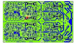
I have to report one error in last batch of the board layout rev. 1.3
There is on short connection showed in attached pictures. The short connection is between the upper trak going from R31 an R15 pad. It's necessary to remove tiny part of the copper between from the top side
I am surprised that no one yet reported problem with this board. Does it mean nobody assembled the board yet?
Sorry for inconvenient.
Damir
Attachments
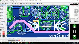
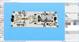
New layout PCB rev 1.0 from Alex mm
Hi,
I think this nice,valorous preamplifier, or phone amp, deserve a decent layout .
Regards Alex
Hi,
I think this nice,valorous preamplifier, or phone amp, deserve a decent layout .
An externally hosted image should be here but it was not working when we last tested it.
; An externally hosted image should be here but it was not working when we last tested it.
;An externally hosted image should be here but it was not working when we last tested it.
Regards Alex
Hi,
I think this nice,valorous preamplifier, or phone amp, deserve a decent layout .
An externally hosted image should be here but it was not working when we last tested it.;An externally hosted image should be here but it was not working when we last tested it.;An externally hosted image should be here but it was not working when we last tested it.
Regards Alex
Nice effort Alex, but you made some positioning errors. What do you think I have positioned some transistor in proximity to each other? To prevent thermal runaway Q15, Q13, Q25 should be in thermal contact, the same for Q16, Q14, Q26. Similar valid for Q11/Q3 and Q12/Q4, but not so critical.
You made the shunt regulator full dual mono, with two transformer. That is good but in my opinion not so important and cost more.
I thank you for good opinion about preamplifier, but it looks that you think my layout is not decent??
Best wishes, Damir
I noticed more errors, in the shunt regulator. You did it on separate board, and in that case it's not good to connect output from the shunt
transistor (mosfet) to the regulation circuit. It should be connected together on the preamplifier board. In case if all on one board not so important as connection is short. Look how I did the same shunt regulator on separate board. Shunt regulator +-15V
Last edited:
Sorry, I did not want, to offend you, my intention, was, to help, but as usual, I have been wrong. It seems, I can never help, only others, are inspired by my work. That is who does not work, does not make mistakes. I will see, my job, and in the future, I will not post any more, who am I to consider? Thank you for opening my eyes ... ... anyway, I have other things, to do more important, than to mess up somebody.
Alex
Alex
Sorry, I did not want, to offend you, my intention, was, to help, but as usual, I have been wrong. It seems, I can never help, only others, are inspired by my work. That is who does not work, does not make mistakes. I will see, my job, and in the future, I will not post any more, who am I to consider? Thank you for opening my eyes ... ... anyway, I have other things, to do more important, than to mess up somebody.
Alex
Alex, I am sorry, I was joking about decent. I don't expect of you to know all requirements about someone's circuit, just correct few things with this layout, that's all. I know that you are very good with layout, you help me a lot in past with my CFA amps. You know for me is much easy to simulate circuits and came to good working one than to layout the same circuit. I need many hours to make a layout and still there left some errors. There are requirements how to lay a layout and I know some but still it's hard to make perfect one. I would like if you can help me in the future, but that requires cooperation between us. If you remember I offer you free of charge some PCBs but you where not interested that time.
I want to make some SMT layouts in near future and I will be grateful if you can help me with it.
Best wishes, Damir

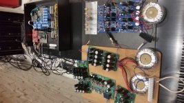
Beautiful work, very nice to see it all together.
The boards you use for the input are not available anymore.
Hope to see it all together with a Power Amp and then hear from you the whole SINGING impressions.
Great Job
1 + 1 = 11
The boards you use for the input are not available anymore.
Hope to see it all together with a Power Amp and then hear from you the whole SINGING impressions.
Great Job
1 + 1 = 11
Hello dadod,
what would you use as SMD mosfet for IRF640 and IRF9640?
JP
I don't think that is possible to find suitable replacement as it needs quite good cooling, so I will stay in that case with the THT, but all small transistors and resistor could be SMD, and the best part is, there are duals in the same case, different combination. I hope, soon I will start with the layout.
By the way (I wrote about it) I use IRF510/9510 for better shunt regulator output impedance.
Damir
Do you have huge dissipating loads like a mosfet or something that needs to be sinked to a metal PCB?
- Home
- Amplifiers
- Solid State
- GainWire Mk3 CFA pre/phone amp with very low distortion