Yes, it actually based on the mk II board, I just started over from scratch and try to place components as nice as possible and take care of the ground.
I'm populating the components, missing some resistors and still wait for the order to complete it.
I'm populating the components, missing some resistors and still wait for the order to complete it.
Last edited:
If you are driving a cable (as in an interconnect cable) you need a lowish output impedance and you need current capability.
A vol pot has an output impedance that varies from zero ohms to Vol Pot resistance divided by 4.
An LED/LDR has a highish output impedance. It also has poor current capability.
You either need a very short, low capacitance cable, or you need to add a Buffer to drive the cable.
A vol pot has an output impedance that varies from zero ohms to Vol Pot resistance divided by 4.
An LED/LDR has a highish output impedance. It also has poor current capability.
You either need a very short, low capacitance cable, or you need to add a Buffer to drive the cable.
I use a short Mogami 2549 cable ~ 30mm to connect the pot to the preamp. So I think it is ok. I also knew the buffer thing and will try it in the future.
I use a short Mogami 2549 cable ~ 30mm to connect the pot to the preamp. So I think it is ok. I also knew the buffer thing and will try it in the future.
Better keep that input resistor at 47k.
what about the length from preamp to power amp?I use a short Mogami 2549 cable ~ 30mm to connect the pot to the preamp. So I think it is ok. I also knew the buffer thing and will try it in the future.
It's the total length of capacitive cable/traces from LED/LDR vol pot to the fitering inside the power amplifier that matters.
what about the length from preamp to power amp?
It's the total length of capacitive cable/traces from LED/LDR vol pot to the fitering inside the power amplifier that matters.
It is DAC -> 30cm -> POT ->30mm ->PREAMP -> 1m POWER AMP.
what about the length from preamp to power amp?
It's the total length of capacitive cable/traces from LED/LDR vol pot to the fitering inside the power amplifier that matters.
No, that is not correct in this case.
Any progress?My balanced version with relays volume controller and inputs selector is slowly being assembled.
What is your listening results using Biino?
Any progress?
What is your listening results using Biino?
Guilty, to much parallel projects, summer heat....,but autumn is the DIY time.
Summer heat is a real enemy for diy,especially when sea is far enough😡Guilty, to much parallel projects, summer heat....,but autumn is the DIY time.
Can you explain the role of R39, R48, C2 network? Why it is not enough to place capacitors around VAS or between output and inverting input for dominant pole compensation?
Can you explain the role of R39, R48, C2 network? Why it is not enough to place capacitors around VAS or between output and inverting input for dominant pole compensation?
R39 and C2 make the current conveyor shunt compensation and R48 defines the current conveyor gain.
More about Loop Gain and the compensation you can find by reading this thread.
There no VAS here in classical terms.
better clipping - mk3.1
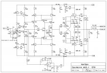
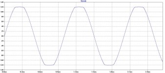
This preamp will deliver up to 12Vp undistorted signal, but when it's go to the clipping it is not soft clipping at all. It is not very important as with so high output all power amp will clip much earlier, or headphones deliver head splitting sound, but why not to have better clipping if it's simple to get it.
Here is simple improvement to get soft clipping, and it's simple to do it on existing board.
Remove R20 and R21 on both channels.
Remove Q21 and Q22 on both channels
Make are short connections (jumpers) between base and emitter on Q21 and Q22 positions, both channels.
This does not worsen distortion at all.
Attached new schematic and clipping plot.
Damir
Attachments
One last try
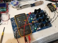
I finally found some time to try this again. I bought fresh new DN2540 and IRF610 and IRF9610's from Mouser. Replaced all the burnt out ones from the last time I tried this. Installing them was a very laborious task given that the through holes are very small so, the slightest trace of solder left over from the previous attempt made it difficult to install fresh MOSFETs. So all installed (while wearing ESD wristrap) and using ESD safe soldering iron.
Plugged it in and no joy: From top to bottom I get 4.6v, -19.8v, 15.0v, -19.8v. The 4.65v one is burning a lot of heat on the MOSFETs, the trimpot does nothing. The 15v one is the only one responsive to the trimpot - which only changes the positive value. The trimpot does nothing to change the voltage on the -19v ones.
All I can say is that I am very perplexed and disappointed in the result. I am not an inexperienced builder with over 3 dozen amps under my belt - and this one is proving very difficult to get working and it's only the PSU portion. If you have any suggestions for debugging that would be good - but I am not sure how much more time (and parts) I can sink into this...
Maybe I should just ignore the PSU portion and use my own +/-15 shunt regulated PSU that I built from Juma's design/Prasi-layout? Really, this should not be so hard.
Attachments
I finally found some time to try this again. I bought fresh new DN2540 and IRF610 and IRF9610's from Mouser. Replaced all the burnt out ones from the last time I tried this. Installing them was a very laborious task given that the through holes are very small so, the slightest trace of solder left over from the previous attempt made it difficult to install fresh MOSFETs. So all installed (while wearing ESD wristrap) and using ESD safe soldering iron.
Plugged it in and no joy: From top to bottom I get 4.6v, -19.8v, 15.0v, -19.8v. The 4.65v one is burning a lot of heat on the MOSFETs, the trimpot does nothing. The 15v one is the only one responsive to the trimpot - which only changes the positive value. The trimpot does nothing to change the voltage on the -19v ones.
All I can say is that I am very perplexed and disappointed in the result. I am not an inexperienced builder with over 3 dozen amps under my belt - and this one is proving very difficult to get working and it's only the PSU portion. If you have any suggestions for debugging that would be good - but I am not sure how much more time (and parts) I can sink into this...
Maybe I should just ignore the PSU portion and use my own +/-15 shunt regulated PSU that I built from Juma's design/Prasi-layout? Really, this should not be so hard.

This very strange, I assembled four boards and PS worked first time.
I suspect some diodes are inserted up side down .
Could you post close photo of ps part?
Just two observation, the heat sinks could be taller, what leds are doung there?
I suggested to use IRF510/IRF9510.
Last edited:
I don't know if this is a double sided pcb but if it's, make sure that heatsinks don't touch traces.
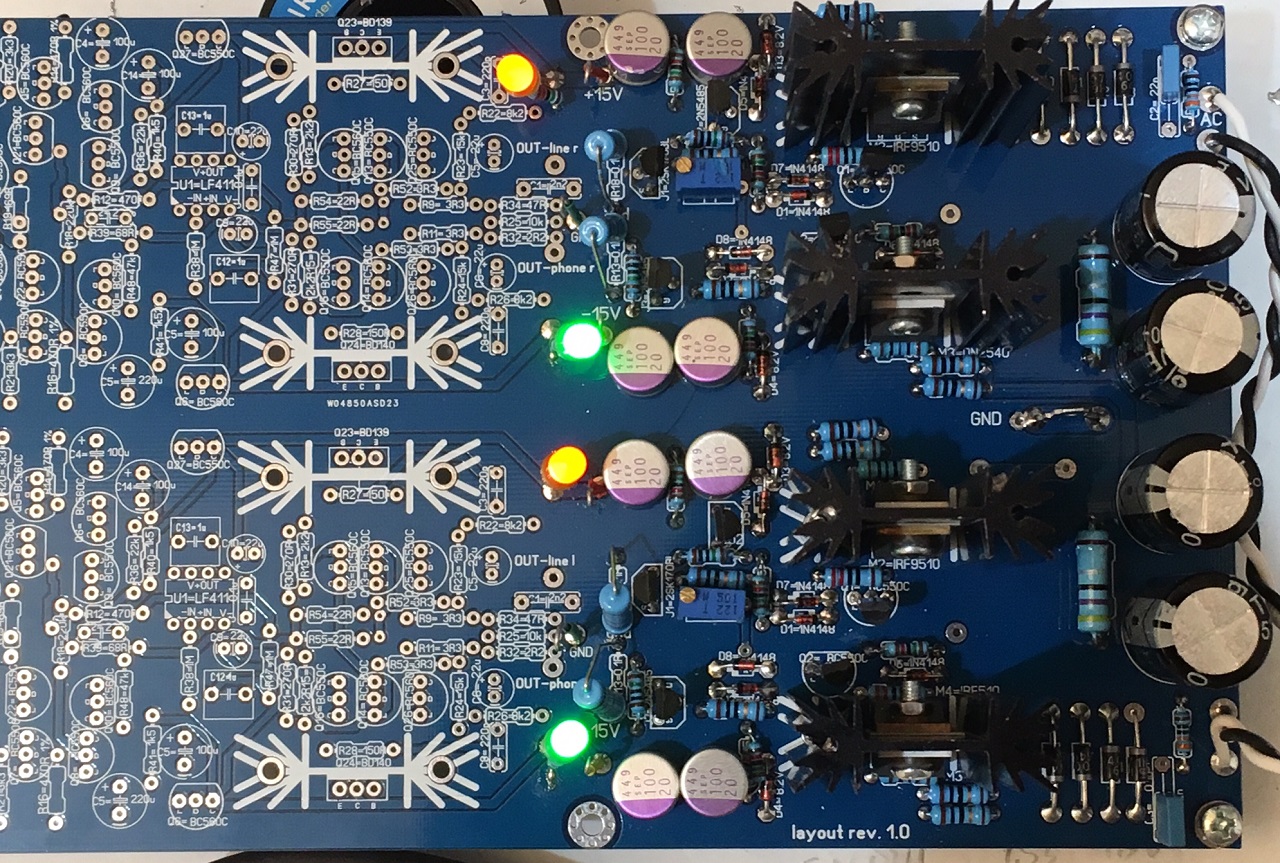
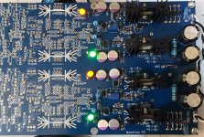
These heatsinks are quite tall - should be able to handle maybe 4W dissipation easily. LEDs with 15k series resistor added for visual indication that circuit is alive. I double checked diode orientation, maybe need to pull them all out and replace or check. Heatsinks have two legs which fit into holes on board designed for them, not soldered in at this point but holes don't connect to any circuit. I will get closeup photo later.
Some progress...
I pulled out the 2SK170 from the top +ve rail and it tested it and it was dead. So was the 2N5485. I did not have anymore 2N5485's so replaced with a 2SJ113 and replaced the 2SK170BL. The top has adjustable voltage now. I decided to change out all the 2N5485's with 2SJ113 so at least they are all consistent. Both +ve supplies shunt regulate to 15.0v well now. However, nothing happens on the negative rails when the trimpot is adjusted. Is the negative rail supposed to be a mirror voltage compared to the postive rail? Why does it not have its own pot?
I went in and pulled out all the BC550 and BC560's in the PSU (they tested fine) but replaced them with fresh ones (also tested prior to installation).
I used a diode tester on all 1N4148's and the 8.2v zeners - they all show typical 0.56v forward voltage drop as a diode should. Their orientations are all correct.
Here is a closeup photo. For 75R resistors, I paralleled two 150R's. For 7k5 I paralleled two 15k's.
So at this point, the positive rails are responsive to pot adjustments. The negative rails just sit at -19.5v and no heat is generated in the MOSFET heatsinks - so no shunting is happening. On postive rails, the MOSFETs are shunting and it is warm but not hot.
Also, in case you are wondering about the tabs on MOSFETs and heatsinks, I am using silicone insulator pads and insulating shoulder washers on bolts and nuts clamping the MOSFETs to the heatsink. I used continuity checker to makes sure none of the tabs are electrically connected to the bolts or heatsinks.
Attachments
Last edited:
xrk: I think your answer is in this post: GainWire mk3 CFA pre/phone amp with very low distortion
Unless the silkscreen error was fixed, both regulator's D8 should be reversed - "cathodes to the right".
TJ
Unless the silkscreen error was fixed, both regulator's D8 should be reversed - "cathodes to the right".
TJ
- Home
- Amplifiers
- Solid State
- GainWire Mk3 CFA pre/phone amp with very low distortion