P3 should be 10k, together with R7 defines the current through the LEDs, so if you increase R7 as I suggested to 15k you will decrease that LEDs current and decrease the voltage LED votage drop and decrease the CCS current and finaly the bias current.
If you don't use P2 then the the value of R4 and R31 should be equal (470R).
If you want to use P2 (10k) then R31 should be 750R and P2 used to set the voltage on P1 connector to zero.
By the way you can't do that without P1 connected, I mean to set to zero, but you can set the bias without P1 connected.
Last edited:
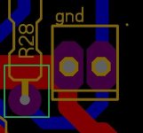
This pcb is kind of cursed! There is a short in one channel around P1, even on a bare board. It's shorted out in the places I've marked, but you can't see anything through the JLCPCB either.
I found it, on the top of the pcb is R28 connected to GND
I found it, on the top of the pcb is R28 connected to GND
Attachments
Last edited:

Damir,
I replaced resistor R7 instead of 6K I put 12K, quiescent current now 165mA / 13,8V, do I leave it like that or replace also the trimmer 5K for 10K?
I replaced resistor R7 instead of 6K I put 12K, quiescent current now 165mA / 13,8V, do I leave it like that or replace also the trimmer 5K for 10K?
Do it like that, try to get the bias of 120mA or close to it. As DN2540 has Idss min of 150 mA (most of them I have it around 200mA) shunt regulator must have enough current going throgh shunt mosfet, let say 50mA, to regulates properly.
Adjust voltage to +-15V too.
Adjust voltage to +-15V too.
What about bias and shunt regulator voltages? Have you cucceeded set it as I suggested?
By the way this is really an amp with no negative feedback, just some local, like very mild emitter degeneration.😉
By the way this is really an amp with no negative feedback, just some local, like very mild emitter degeneration.😉
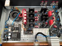
I got a new transformer, on which I left the primary at 230V, because I live close to the substation in the network I have 237V which gave me a slightly higher secondary (16.2V AC). I ended up at 33k (R7), after settling I have a bias of 145mA and the shunt regulator goes up to 15.5V, after about 30 min of overclocking I set it to 15V
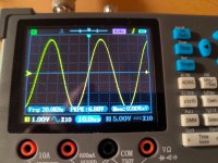
No listening result yet?No oscillations, ...tomorrow I will finally listen to it, I wonder if it will sound better than SMSL H400
Today I hastily plugged it in, I listened to it only as a preamp and I can confirm that it plays great for me.
a, smsl mda raw 1+ smsl h400 + amp SA2014 (2x 400W) , ...i don't know i can't get used to the sound yet i miss the deepest bass ones there , ...i rate this combination at 70%
b, smsl mda raw 1 + amplifier SA2014 (2x 400W), the sound is even worse midrange is ok but the bass is even more plastic so artificial... 60%
c, smsl mda raw 1 + gainwire + SA2014, ...the sound gained in dynamics suddenly there is even more bass than in connection a, 80%
I feel like the dac is to blame, it doesn't have the vibe I imagined.
On position P1 I have attenuator, I have to replace it with blue alps, (stepped attenuator is unsuitable on this position...)
I am using stepped attenuator in one of mine NGNFB GW with no problem, it should be make before break and input connected to the output so that act as a log rheostat.
In other one I used motorized RK 27 Alps pot with good result.
In other one I used motorized RK 27 Alps pot with good result.
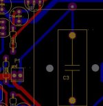
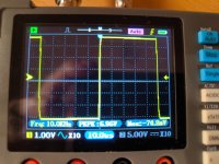
New udate: The stepped attenuator makes an unpleasant sound when adjusting between steps. On P1 before the capacitor there was 48mV in one channel and 38mV in the other. I trimmed it close to 0mV and these unpleasant sounds between each step suddenly disappeared.
I could never solve the zipper effect (I am not a SW guy) and it was hard to explain what I wanted to my programmer to implement. I eventually ditched the idea and just used a simple switch stepped attenuation. Turning it fast or slow did not matter. If I may give an opinion that the zipper effect is due to the binary code, if it was just a series of relays it would probably not happen.
I used rotary stepped attenuator. I haven't found relay stepped attenuator I could connect as rheostat what is needed here.
Because no DC current going through P1.New udate: The stepped attenuator makes an unpleasant sound when adjusting between steps. On P1 before the capacitor there was 48mV in one channel and 38mV in the other. I trimmed it close to 0mV and these unpleasant sounds between each step suddenly disappeared.
Sometimes it makes an unpleasant sound between each step when adjusting the volume and other times it is completely silent. What would help it to always be quiet? The classic potentiometer?
I bet you won't notice the pop sound if you use the DACT or Elma attenuator. I bought many Khozmos and while the build looks awesome, some of the switches randomly make annoying switching sound. Never experienced that with the DACT.Sometimes it makes an unpleasant sound between each step when adjusting the volume and other times it is completely silent. What would help it to always be quiet? The classic potentiometer?
- Home
- Amplifiers
- Solid State
- GainWire line/phone non GNFB preamp