I never had a chance to hear that expesive headphones, but according to some reviews it does not need a lot of power.

passive420 sold me a PCB V1.0. Thanks again.
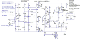
Meanwhile I built the input stage with the components shown in the attached schematic. The BC550/BC560 I bought where matched for hfe of 600@5mA (+/-25). Vbe of BC560C was 0.718 (+/- 2mV) while BC550C was 0.728 (+/-2mV).
2 parts values were changed:
R19 (2k2 instead of 2k5)
C2 (22p instead of 15p).
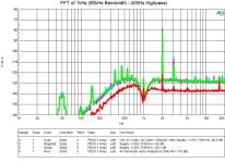
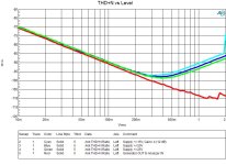
The buffer stage isn't built yet nor is the shunt regulator. For measurments I used a lab supply and a simple diamond buffer. Some noise can be seen from the power supply and the cabling. In general the performance isn't bad but quite a bit away from simulations. THD+N is around -90 dB (0.003%) and dominated by the second harmonic. Performance improves if the supply voltage is increase from 15V to 25V. With a gain of 4.4 (P1=10k/R19=2k2) the performance is best with input levels around 0.4 to 0.5V.
As this is my first post here I am cautious to jump into conclusions. What do you guys think about the results?
Rainer
Meanwhile I built the input stage with the components shown in the attached schematic. The BC550/BC560 I bought where matched for hfe of 600@5mA (+/-25). Vbe of BC560C was 0.718 (+/- 2mV) while BC550C was 0.728 (+/-2mV).
2 parts values were changed:
R19 (2k2 instead of 2k5)
C2 (22p instead of 15p).
The buffer stage isn't built yet nor is the shunt regulator. For measurments I used a lab supply and a simple diamond buffer. Some noise can be seen from the power supply and the cabling. In general the performance isn't bad but quite a bit away from simulations. THD+N is around -90 dB (0.003%) and dominated by the second harmonic. Performance improves if the supply voltage is increase from 15V to 25V. With a gain of 4.4 (P1=10k/R19=2k2) the performance is best with input levels around 0.4 to 0.5V.
As this is my first post here I am cautious to jump into conclusions. What do you guys think about the results?
Rainer
Attachments
You have to use 0.1% resistor for R5/R6 and R14/R16. If there is higher differences you will get higher THD mostly second harmonic, what could be very pleased sound.
interesting .... you want to use 0.1% resistors at those positions, but what about the VBE differences between Q1/Q5 (PNP) and Q2/Q7 (NPN)? And also at other bias points in the circuit between PNP and NPN sides?
Thanks for the advice Dadod. In fact I used 1% resistors. Spice simulation confirms that changing only R5 from 1000 to 1001 increases 2nd harmonic distortion by about 20dB. Change in Vbe does change only DC offset. I will look for high precision 1k resistors and repeat the measurments.
If a 1/1000 change in resistance affects the distortion by 100 times you are on a bad margin and on the conduction knee of a semi conductor component, no a good place to be. Can you run your simulator at a different temperatures and see what happens.
Temperature dependency is very low. THD+N increases slightly if temperature is increased (around 1-2dB within 27-50 degree C). I did this with the .temp command. With this the whole circuit is on the same temperature. Not sure if the transistor model of BC550C/BC560C supports temperature simulations...
Anyhow, the circuit runs with a DC bias of around 2.2 - 2.3 mA. With 2.5V peak input voltage and R19 = 2k5 the AC current is +/- 0.5mA. This makes the AC current in relation to the DC bias is pretty high (about a 1/5). If we would increase R19 (3k3 or 4k7) and/or increase the DC bias current (reduce R4/R31 to 470 or 330) the dependency on the resistor tolerances is reduced - at least in simulations.
Increase of R19 will increase noise which is most likely acceptable as we have now SNR of more than 110 dB. Increase of the DC bias current - even doubling it won't have any negative impact (please correct me if I am wrong here). With the 2mA today and the +/-15V supply, we have a max power dissipation transistors Q11/Q12 of around 30mW.
Until I receive the high precision resistors, I will try the 2 scenarios above... Any comments or suggestions are welcome.
Last edited:
This preamp is using current conveyor and those resistors are in the emitters of the current conveyor with quite high value (1k) to keep the noise lower.If a 1/1000 change in resistance affects the distortion by 100 times you are on a bad margin and on the conduction knee of a semi conductor component, no a good place to be. Can you run your simulator at a different temperatures and see what happens.
rfinck,
If you change R19 value you change the preamp gain as the ratio P1/R19 defines the gain. This preamp does not attenuates input signal just change the gain by chanfing the P1 value (I use potentiometer connecte as rheostat - variable resistor). I vould call it Gain control not Volume control.😉
Damir
If you change R19 value you change the preamp gain as the ratio P1/R19 defines the gain. This preamp does not attenuates input signal just change the gain by chanfing the P1 value (I use potentiometer connecte as rheostat - variable resistor). I vould call it Gain control not Volume control.😉
Damir
I played with this possibility look here https://www.diyaudio.com/community/...ne-non-gnfb-preamp.395695/page-2#post-7591547Thanks for the advice Dadod. In fact I used 1% resistors. Spice simulation confirms that changing only R5 from 1000 to 1001 increases 2nd harmonic distortion by about 20dB. Change in Vbe does change only DC offset. I will look for high precision 1k resistors and repeat the measurments.
and included it in one of minen preamp. I used small relay to connect 47k resistor parallel to R14. I could not hear differences with it connected and without, probably because of my age.
Hi GainWire Fans 🙂
Today I am testing SMSL MDA RAW 1 (2x ES9039Q2M) + SMSL H400 (discrete fully balanced pream/headamp).

It sounds really amazing, but I think GainWire is a bit better, but I don't dare to say that I would recognize them in a blind test. So far I have it connected asymmetrically (only cinch), waiting for symmetrical cabling. But I think that with symmetrical connection SMSL H400 will be a clear winner.
Have a nice day and good luck...
Today I am testing SMSL MDA RAW 1 (2x ES9039Q2M) + SMSL H400 (discrete fully balanced pream/headamp).
It sounds really amazing, but I think GainWire is a bit better, but I don't dare to say that I would recognize them in a blind test. So far I have it connected asymmetrically (only cinch), waiting for symmetrical cabling. But I think that with symmetrical connection SMSL H400 will be a clear winner.
Have a nice day and good luck...
HRDSTL if I remember correctly you buit GW CFA version, did you build NGNFB version too.
SMSL H400 is quite expensive, 500 EUR or so and 15W/16R.
Damir
SMSL H400 is quite expensive, 500 EUR or so and 15W/16R.
Damir
Last edited:
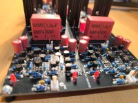
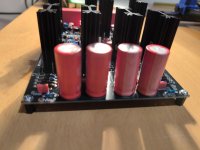
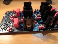
I just finished the red edition of GainWire. I'm just waiting for the transformer, which is already on its way to me.
Attachments

Hi Damir,
First test, everything fine, ...I worked without error, no smoke or explosion. 🙂
DC output up to 100mV without servo. I can only set the voltage in the shunt regulator to max 13,5V (R7 --1k trimpot) in both channels, but I think it will be enough. The heatsinks on the output buffers are quite hot, how much mA to set the current through the mosfets?
Bias is set to 185 mA / 13,5 V
Attachments

Last edited:
Lateral Mosfets, according to research dissertation presented by TI engineer produces lowest distortion at about 100 mA bias current (each if paralleled or single). I can't confirm or deny this but has always followed his rule and I find it acceptable. They therefor run pretty hot using higher supply voltages.
The bias is to high, it should be around 120mA or so. If to high CCS (DN2540) will saturate and that is the reason you can't set the shunt regulator voltage to +-15V.
Damir
Damir
Hi Damir, I will readjust bias to your recommendation and measure if there is a performance improvement @ +20mV, I am already dissipating some 50 watt at idle but, my heat sinks are oversized anyway and that should ease the pain. It would be interesting and may change my rule of thumb.
The bias voltage on the output buffer can be set between 270mV and 295mV by measuring the R1/R3 (1R5). What would you suggest where to find fault?
Red LED could differs and if the voltage drop is a bit higher it can generare higher CCS (Q23/24) current. Try with higher value for R7, let say 15k.
- Home
- Amplifiers
- Solid State
- GainWire line/phone non GNFB preamp