[off topic 😉 ]
about that 47labs player. When i was at our local high end audio shop some time ago i had the pleasure to be able to hear both the 47labs thing and a linn sondek cd12 in the same system.
The differences between the two, imho, are more a matter of taste than a matter of quality. I actually preferred the cd12. It seems to have a somewhat more relaxed sound, where the 47labs is a little more on the rough side.
[/offtopic]
[
Matjans,
If you're referring to the picture I posted, I'm only using it as a transport. My DAC is home built with a tube stage, but people have been using the shigaraki DAC with the gaincard power supply (as apposed to the cube it comes with) to great results. Or battery powered.
As a transport it is sublime. Eventually I'll build a transport too to claim an all home made system, but I haven't had the time, and I'm not sure it would sound better.. Transports are tricky. The shigaraki transport seems to compensate for the CD wobbliness. You can see the laser pickup vibrate on some disks to compensate, ie. mechanical correction vs bit correction.
]
center tapped confusion
I recently attempted the wiring scheme suggested by Sherman...
" The center tapped transformer is running through both bridges (just like a "real" transformer).
Wiring was done like this-
AC1 from transformer to AC1H on PS board, CT from transformer to AC1N and AC2H on PS board and AC2 from transformer to AC2N on PS board."
but it didn't work... the scheme appears to allow current to flow from the CT through pg1 to pg2 and then to AC2. Thus causing a short when the grounds are connected.
What am I doing wrong?
Thanks,
Steve
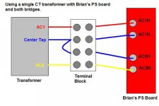
Re: center tapped confusion
Steve,
Below is a diagram of how I connected my CT transformer to Brian's PS board.
Here are the specifics: My transformer is a 40VCT which gives 20VAC between lead one and the CT and 20VAC between lead two and the CT. As you stated PG+ and PG- are connected on the amp board. That means they *must* come from the same lead on the transformer or it will cause a short (I know from experience!).
On the PS board AC1N becomes PG+ and AC2H becomes PG- for output to the amp. That means that AC1N and AC2H have to be from the same lead on the transformer or it will short. If both AC1N and AC2H are from the same lead I don't know how that could cause a short, you are basically connecting a lead to itself, no problem with that.
I wired my transformer as in the diagram below. I connected the trafo leads to a terminal block and used a jumper wire to double up the ct as illustrated. I then wired from the terminal block to the ps board as if I had a dual secondary transformer, treating the ct leads as both AC1N and AC2H.
I hope that helps.
steve said:I recently attempted the wiring scheme suggested by Sherman...
but it didn't work... What am I doing wrong?
Thanks,
Steve
Steve,
Below is a diagram of how I connected my CT transformer to Brian's PS board.
Here are the specifics: My transformer is a 40VCT which gives 20VAC between lead one and the CT and 20VAC between lead two and the CT. As you stated PG+ and PG- are connected on the amp board. That means they *must* come from the same lead on the transformer or it will cause a short (I know from experience!).
On the PS board AC1N becomes PG+ and AC2H becomes PG- for output to the amp. That means that AC1N and AC2H have to be from the same lead on the transformer or it will short. If both AC1N and AC2H are from the same lead I don't know how that could cause a short, you are basically connecting a lead to itself, no problem with that.
I wired my transformer as in the diagram below. I connected the trafo leads to a terminal block and used a jumper wire to double up the ct as illustrated. I then wired from the terminal block to the ps board as if I had a dual secondary transformer, treating the ct leads as both AC1N and AC2H.
I hope that helps.
Attachments
Hi Sherman...
Thanks for your reply.. Guess I'm still a little confused... do you mean that you didn't use the pg1 and pg2 outputs, but rather connected AC1n and AC2h as the ground terminals to the amp?
thanks again..
Steve
Thanks for your reply.. Guess I'm still a little confused... do you mean that you didn't use the pg1 and pg2 outputs, but rather connected AC1n and AC2h as the ground terminals to the amp?
thanks again..
Steve
Oops...
I guess I was a little hasty in my response... I see that you did indicate that AC1n and AC2h were used as pg1 and pg2... If this is the case, then where do you tap off for your V+ and V- ? I'm still confused... Sorry...
Thanks
Steve
I guess I was a little hasty in my response... I see that you did indicate that AC1n and AC2h were used as pg1 and pg2... If this is the case, then where do you tap off for your V+ and V- ? I'm still confused... Sorry...
Thanks
Steve
steve said:Hi Sherman...
... do you mean that you didn't use the pg1 and pg2 outputs, but rather connected AC1n and AC2h as the ground terminals to the amp?
thanks again..
Steve
No, I connected the wires to the "AC input" section of the power supply board as shown in the previous diagram. I then connected all the outputs to the amp boards as shown in the diagram below.
Please note the wire colors are for clarity only, they are not the same as in the previous diagram!
The CHG wire is connected to the ps chassis and to the amp chassis as well as to the amp boards, it does not come from the ps board.
Attachments

OK to clarify even more where the wires come from. The AC and CT wires from the transformer connect to the AC1H, AC1N, AC2H, AC2N points on the PS board as shown in the first diagram.
In this diagram- red is V+ from the PS board, black is PG+ from the PS board, yellow is V- from the PS board, blue is PG- from the PS board. Those connections are on the opposite edge of the PS board from the AC connections.
The green wire is the chassis ground, it connects to a screw in the PS chassis and to the ground wire in my AC cord from the wall socket, it doesn't come from the PS board at all.
continued confusion
Hi Sherman...
Thanks for your efforts to help me out here... I guess I must be a lot slower than I thought.. but I can't see how it can work. I've tried to sketch out your schematic, and unless I still have something mixed up, it seems that connecting pg1 with pg2 will allow current to flow from CT to AC2 and from AC1 to AC2.
Again, I really appreciate your efforts to help me out..
Thanks
Steve
Re: continued confusion
Steve,
I am out of ideas. My power supply is wired as described and is connected to the amps as described and it works fine. It has been running for over a week and at normal and slightly loud listening levels the transformer doesn't even get truly warm and the heatsinks on the amp get only slightly warm to the touch.
I originally tried wiring it with the CT feeding both "N" connections (that "seemed" intuitive, using the AC1 and AC2 leads from the transformer as the "hot" leads and the CT as both "neutrals" but that resulted in a blown fuse when power was applied. I changed to this scheme and it worked.
steve said:Hi Sherman...
... but I can't see how it can work. I've tried to sketch out your schematic, and unless I still have something mixed up, it seems that connecting pg1 with pg2 will allow current to flow from CT to AC2 and from AC1 to AC2.
Again, I really appreciate your efforts to help me out..
Thanks
Steve
Steve,
I am out of ideas. My power supply is wired as described and is connected to the amps as described and it works fine. It has been running for over a week and at normal and slightly loud listening levels the transformer doesn't even get truly warm and the heatsinks on the amp get only slightly warm to the touch.
I originally tried wiring it with the CT feeding both "N" connections (that "seemed" intuitive, using the AC1 and AC2 leads from the transformer as the "hot" leads and the CT as both "neutrals" but that resulted in a blown fuse when power was applied. I changed to this scheme and it worked.
Sherman,
What is the difference between going from the CT to both neutrals, and going from the CT to the block then to the neutrals. Am I missing something here?
What is the difference between going from the CT to both neutrals, and going from the CT to the block then to the neutrals. Am I missing something here?
Jamh said:Sherman,
What is the difference between going from the CT to both neutrals, and going from the CT to the block then to the neutrals. Am I missing something here?
I am out of my depth in trying to understand what is actually going on with the electrons in the system. Heck, I'm still pretty sure all this stuff really does operate on magic smoke!
With my limited understanding of the theory I have to rely on actually wiring it up and turning it on. It didn't work with the CT on both neutrals, it works perfectly the CT on one hot and one neutral.
Could I have had so-mething else mis-connected when I tested it the first way? Possibly, but before putting everything in the cases I had it laid out on a pine board with all the wires labeled and connecting via terminal blocks. When it blew a fuse I just disconnected the CT from one terminal and an AC from one terminal, swapped them, changed the fuse and powered it up again.
How about this- could it be that because there is some continuity between the AC and DC side of things that one set of hot and neutrals "become" the V+ and V- and the other set "become" PG+ and PG-? If the PGs are then connected at the amp and they aren't both originating on the same physical wire from the transformer that it causes a short just like directly connecting AC1 and AC2 out of the transformer?
Just my guess based on the behavior of the thing.
Hi. Sherman..
Thanks again for all your efforts.. I will have to go back and check all my rectifiers to make sure that I don't have a dud.. It has been frustrating to try to duplicate a simple wiring layout and not get similar results, but I'm glad that it works for you.
Thanks again...
If anyone else might have any ideas as to why I can't seem to get this to work, I would sure appreciate any input..
Thanks
Steve
I'm 99% done designing my chassis and I'm at a crossroads. I need a little help.
Pretend you're looking at an H shaped chassis from above, the horizontal line seperating the PS from the amp section. Do you see a problem with RFI/EMI from the PS when using that horizontal divider as a heat sink? It will be made of copper clad aluminum 1/2" thick. Thanks.
Pretend you're looking at an H shaped chassis from above, the horizontal line seperating the PS from the amp section. Do you see a problem with RFI/EMI from the PS when using that horizontal divider as a heat sink? It will be made of copper clad aluminum 1/2" thick. Thanks.
On the sound of these amps, I ended up bringing the little one I posted on this forum to this guy's place whose company makes and sells high end ribbon speakers (>20K) in LA, and we did a lot of AB on his speakers with different amps, and I'll tell you, it wasn't hard to pick which one had the most air and smoothest grainfree sound. The mids and highs were so clear and extended on his 100db speakers you wouldn't believe. We didn't try the lows, he was running his Focal woofer separately with an active crossover and it was too hard to mess with that. Anyways, here's a list of amps we beat in mid-highs:
Pass Aleph, threshold, copland, carver (tubed) and another tube amp I forget the name, chinese. He asked if we used silver plated PCBs! Didn't know they existed. Anyways, I guess I'll be making one for him.
Pass Aleph, threshold, copland, carver (tubed) and another tube amp I forget the name, chinese. He asked if we used silver plated PCBs! Didn't know they existed. Anyways, I guess I'll be making one for him.
I was smiling looking at all different BrianGT GC built so far...I guess Peter Daniel has such influence on trend/fashion of these amps appearances. Now mesh top plate seems to be the in thing. But looking back to the ClassA amps built by our fellow members many of those used solid aluminium top plate instead.
IMHO the chip amp does not really need such top for heat displacement. I hope builders were using the mesh top based on look only and not because they thought the GC need that to relief that much of heat. In fact those ClassA amps should be using these mesh top plate more so than the GC I think..
Chris 😉
Main reason for me to use mesh top is to avoid the influence of the top cover on amp's sound. It is pretty common that removing the panel from the equipment improves the sound (it is the case with my ML chassis as well).
So by using perforated cover, we are getting closer to no cover at all. It has nothing to do with heat dissipation or looks. Although with such small sizes, disipation capabilities are quite important and I think perforation improves this as well.😉
So by using perforated cover, we are getting closer to no cover at all. It has nothing to do with heat dissipation or looks. Although with such small sizes, disipation capabilities are quite important and I think perforation improves this as well.😉
Just wanted to post a followup on my progress regarding my problems using a center tapped transformer.. I recalled that Peter Danials had reported using the same transformer that I was working with so I e-mailed him to ask how he implimented the bridge.. He replied that he had converted the center tapped transformer to dual secondaries by opening up the outer tape where the center tap is attached and simply disconnecting the two secondary neutrals that are tied to the center tap... I followed this procedure and... works great... thanks again PD.
Steve
Steve
- Status
- Not open for further replies.
- Home
- Amplifiers
- Chip Amps
- Gainclone building thread based on BrianGT's boards