This is bad..... I just ruined my amp by moving the transformer on yesterday. It spiked once when I try to put the transformer back into the chassis, then I quickly turned off the power. The next time I turned it on, the speaker have bu..... sound. Then I knew I messed it up again. It is lucky that I am wearing plastic gloves in this operation. So no one can answer me why the tranformer heating up the entire chassis? I am surtain that the transformer causes the heat, and the whole chassis and the heat sink is fine when I removed the transformer from the chassis. This transformer wasn't causing heat before, because I had been using this transformer since the first IGC I had completed, and the 3 weeks testing of brain's board with out the chassis. I remember it is not even warm when I touched it after running for a day. Besides this problem, how can I isolate the transformer form the chassis that the plastic warp of the transformer started to break. Can I warp it over with some sort of electronical tape to prevent the next shorting?
P.S: It has been a caurse to me that my first complete will always result of a failure. It has been like this since my Chy Moy, IGC, and NIGC.....
P.S: It has been a caurse to me that my first complete will always result of a failure. It has been like this since my Chy Moy, IGC, and NIGC.....
S.C said:This is bad..... I just ruined my amp by moving the transformer on yesterday. It spiked once when I try to put the transformer back into the chassis, then I quickly turned off the power. The next time I turned it on, the speaker have bu..... sound. Then I knew I messed it up again. It is lucky that I am wearing plastic gloves in this operation. So no one can answer me why the tranformer heating up the entire chassis? I am surtain that the transformer causes the heat, and the whole chassis and the heat sink is fine when I removed the transformer from the chassis. This transformer wasn't causing heat before, because I had been using this transformer since the first IGC I had completed, and the 3 weeks testing of brain's board with out the chassis. I remember it is not even warm when I touched it after running for a day. Besides this problem, how can I isolate the transformer form the chassis that the plastic warp of the transformer started to break. Can I warp it over with some sort of electronical tape to prevent the next shorting?
P.S: It has been a caurse to me that my first complete will always result of a failure. It has been like this since my Chy Moy, IGC, and NIGC.....
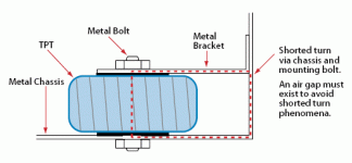
What parts are ruined? I can send you some extra parts to get you going again. As for the transformer, can you post some pictures of how you had it mounted? Make sure that you don't have a shorted turn. See attached image for illustration.
A thread detailing the problem:
http://www.diyaudio.com/forums/showthread.php?s=&threadid=30676
--
Brian
Attachments
I mounted it like your post #469 without the ac inlet aginsting the tranformer, instead my chassis wall and the heatsink are tightly keep the transformer in place which is a bad thing..... btw I haven't check which of the compents are fired yet, so Brian don't need to worry. And thx for your offer, but I got extra parts form the my IGC first failure...... 5 more LM3875 including the one on my IGC to go and two fully functional bridge. I hope those LM3875 are fine cuz I am planning to bridge it to make a sub amp with the Mox crossover.
Addition: Oh great I got a short turn then...... It matches everything they said in that thread. My bolt got hot too. AM I going to need a new chassis? Am I spending those $100 for nothing.....T_T😡
Addition: Oh great I got a short turn then...... It matches everything they said in that thread. My bolt got hot too. AM I going to need a new chassis? Am I spending those $100 for nothing.....T_T😡
hi all, What is the best pot to go with Brain's kit ? (I know someone might have asked it before but it's not easy to find).
Maybe not best but...
I don't know if it is the "best" but I used a 100K stereo pot with mine because I had a couple in the bin. It has worked out fine. The fully attenuated position is about 7 o'clock and the max volume position is about 4 o'clock. My "normal listening level is between 8:30 and 9 o'clock with good control in that range. I haven't used it turned past about 12 o'clock as it is very loud by that point.
yuval said:hi all, What is the best pot to go with Brain's kit ? (I know someone might have asked it before but it's not easy to find).
I don't know if it is the "best" but I used a 100K stereo pot with mine because I had a couple in the bin. It has worked out fine. The fully attenuated position is about 7 o'clock and the max volume position is about 4 o'clock. My "normal listening level is between 8:30 and 9 o'clock with good control in that range. I haven't used it turned past about 12 o'clock as it is very loud by that point.
I have used perforated top plate because I thought I needed that due to heat but the fact is that this is only making the amp collecting dust => very bad for the sound...Peter Daniel said:So by using perforated cover, we are getting closer to no cover at all. It has nothing to do with heat dissipation or looks. Although with such small sizes, disipation capabilities are quite important and I think perforation improves this as well.😉
 seriously I would go for a dust proof cover and if anyone feels that this has influence on the the sound, make a test first.
Holes = Good sound, No holes = very bad sound => if true, use perforated plate.
Perhaps this is discussed somewhere else, but how can the cover affect the sound? What are the physics of the situation that would cause a difference in sound aside from interference from outside sources?
I'm confused...😕
I'm confused...😕
Don't be ashamed for that. Put CD in a freezer, does this really work in order to better sound or this: put a safety pin in the curtain....😱 Don't believe everything you hear and/or verify this by tests of your own 
I'm not ashamed persay...I'm just curious if anyone has a physical explanation for it versus the "I tried it and it sounded better" explanation.
Oh, and doesn't everyone keep their CDs in the fridge? 😀
Oh, and doesn't everyone keep their CDs in the fridge? 😀
In my case, are there any ways to solve the problem without remaking the whole chassis? Plz help guys !
Couldn't you just attempt to insulate the TPT so you don't attain the loop? Isolate it from the chassis and break the short...
In my case, are there any ways to solve the problem without remaking the whole chassis?
You could use a plastic bolt.
widman said:You could use a plastic bolt.
I like to just hold the things down with multiply zip straps.
dave
wiring potentiometers
sooooo. I have my brian gt premium gc all most done. everythingis mounted in the chassis. and i got the power all wired and the binding post are all mounted. just need to wire the noble 25k pot i have and im ready to try it out. i just have no idea how to wire this dual 4 pin pot. i assume that there is one for ground and one for input and one for output. with the fourth for loudness. so i have read. i have been searching for a while but i cant find a diagram or info on how to wire this. i have no instructions and the noble site was no help. please someone give me a clue. Tia
Tia
sooooo. I have my brian gt premium gc all most done. everythingis mounted in the chassis. and i got the power all wired and the binding post are all mounted. just need to wire the noble 25k pot i have and im ready to try it out. i just have no idea how to wire this dual 4 pin pot. i assume that there is one for ground and one for input and one for output. with the fourth for loudness. so i have read. i have been searching for a while but i cant find a diagram or info on how to wire this. i have no instructions and the noble site was no help. please someone give me a clue.
TiaI have a 10K noble pot and wired it (counting pins left to right) with pin 1 to ground, pin 2 to output and pin 3 to input and nothing to pin 4.
Re: wiring potentiometers
I believe the 4th post is a 40% tap. Just don't use it.
If you don't know which pins are which just put a meter on them. The input and output pins will have max resistance between them with the shaft rotated fully anti-clockwise. Signal ground will be the opposite with max resistance between is and the output pin with the shaft rotated fully clockwise.
Nothing bad happens if you mix up input and signal ground except that your volume control will work backward (been there, done that, late night, don't ask).
slappomatt said:sooooo. i just have no idea how to wire this dual 4 pin pot. i assume that there is one for ground and one for input and one for output. with the fourth for loudness.
I believe the 4th post is a 40% tap. Just don't use it.
If you don't know which pins are which just put a meter on them. The input and output pins will have max resistance between them with the shaft rotated fully anti-clockwise. Signal ground will be the opposite with max resistance between is and the output pin with the shaft rotated fully clockwise.
Nothing bad happens if you mix up input and signal ground except that your volume control will work backward (been there, done that, late night, don't ask).
thanks guys. yeah wildman thats about what i figured out with my ohm meeter but im glad you back that up. although after getting frustrated with the pot i tried to just hook it up without and had problems even b4 i got it to play. so i guess i have to take it apart tonight and trouble shoot something. didnt get any smoke yet.  but i did see a flash and it blew a fuse. guess i didnt do something right 😕 😕
but i did see a flash and it blew a fuse. guess i didnt do something right 😕 😕What Iron is too hot for BrianGT's PCBs?
Hello All!
Thanks to everyone for all your great info about building Gainclones. Special ShoutOut to BrianGT!!!!! 😀
I recently bought a few of BrianGT's PCBs. I read his manual w/pics too. (A big help)
I'm a newbie to sodering, so I read the part of his PDF manual about sodering. He mentioned not using an Iron rated above 35w. So I went out and bough a Weller WES51 soddering station. But it's small iron is rated 50w. Though it does have heat control.
If I turn the heat all the way down do ya'll think it will work well sodering PCBs? Or should I buy a new iron rated lower for this Weller WES51?
Thanks!
- Status
- Not open for further replies.
- Home
- Amplifiers
- Chip Amps
- Gainclone building thread based on BrianGT's boards