To all who recently submitted orders, all remaining orders have been shipped out earlier today.
If you submitted an order more than 2 weeks ago, and haven't received it, drop me an e-mail, and I will check my records. All recent US orders will have USPS Delivery confirmation numbers, which I had e-mailed out when I purchased the postage.
I am still accepting orders for basic kits and pcb sets. I am hoping to be able to offer the premium kits again soon, but it seems like the lead times on the resistors are insanely long, at least another week.
If you want to order boards or basic kits, see my webpage:
http://www.BrianGT.com/order/
I will continue shipping orders out. The current turn-around time is a day or two.
--
Brian
Just an update...
I'm not sure exactly how long it's been, but I just thought I'd mention that my gainclone that I'm running on ±48V rails (because I didn't have another transformer on hand with a more suitable secondary voltage [36-0-36 CT], and I didn't want to buy one) is still working fine and still sounds great. So it seems that if you have a transformer lying around with 30-35V secondaries, you can use it for a gainclone if you can't buy a new one, or simply want to put it in something. However, I certainly wouldn't connect this to a good (expensive) pair of speakers, at least not without a separate protection system on the outputs to prevent damage in the event one of the chips fails.
 Do not interpret this as a "suggestion" to intentionally overvolt any component. I did this out of necessity, and because I fully understood the risks involved, and was willing to accept those risks. All chips are not the same, and some may be more resilient to higher voltages than others. My chips are also particularly well-cooled, and I do not have to worry about their overheating. If you have or can buy a transformer with more suitable secondary voltages (20-30V), then do not use a higher secondary voltage unless you simply want to experiment and are willing to accept the risks of pushing the envelope. National specifies that ±42V rails is the maximum voltage for the LM3875, and exceeding that places your amplifier and speakers at risk.
I'm not sure exactly how long it's been, but I just thought I'd mention that my gainclone that I'm running on ±48V rails (because I didn't have another transformer on hand with a more suitable secondary voltage [36-0-36 CT], and I didn't want to buy one) is still working fine and still sounds great. So it seems that if you have a transformer lying around with 30-35V secondaries, you can use it for a gainclone if you can't buy a new one, or simply want to put it in something. However, I certainly wouldn't connect this to a good (expensive) pair of speakers, at least not without a separate protection system on the outputs to prevent damage in the event one of the chips fails.
Do not interpret this as a "suggestion" to intentionally overvolt any component. I did this out of necessity, and because I fully understood the risks involved, and was willing to accept those risks. All chips are not the same, and some may be more resilient to higher voltages than others. My chips are also particularly well-cooled, and I do not have to worry about their overheating. If you have or can buy a transformer with more suitable secondary voltages (20-30V), then do not use a higher secondary voltage unless you simply want to experiment and are willing to accept the risks of pushing the envelope. National specifies that ±42V rails is the maximum voltage for the LM3875, and exceeding that places your amplifier and speakers at risk. Re: Just an update...
Thanks for the update. I'm not an electronics expert and don't even play one on TV. I learn best by doing, screwing it up and then fixing it, a sometimes expensive but always effective learning method. I have been amazed by the tolerance of these chips for mistreatment (or boundary pushing depending on your point of view 😉 ). Plus they sound good!
Have you had a chance to compare the sound of your amp to a more "reasonably" powered one? I've heard that some think lower voltages sound better. My own gc based on Brian's boards is powered by 27VDC and I think it sounds great. I'd like to build another (or more) and wonder if the difference of say 27VDC and 18VDC would be audible, other than max power output.
tpenguin said:... my gainclone that I'm running on ±48V rails ... is still working fine and still sounds great.
Thanks for the update. I'm not an electronics expert and don't even play one on TV. I learn best by doing, screwing it up and then fixing it, a sometimes expensive but always effective learning method. I have been amazed by the tolerance of these chips for mistreatment (or boundary pushing depending on your point of view 😉 ). Plus they sound good!
Have you had a chance to compare the sound of your amp to a more "reasonably" powered one? I've heard that some think lower voltages sound better. My own gc based on Brian's boards is powered by 27VDC and I think it sounds great. I'd like to build another (or more) and wonder if the difference of say 27VDC and 18VDC would be audible, other than max power output.
steve said:Just wanted to post a followup on my progress regarding my problems using a center tapped transformer.. I recalled that Peter Danials had reported using the same transformer that I was working with so I e-mailed him to ask how he implimented the bridge.. He replied that he had converted the center tapped transformer to dual secondaries by opening up the outer tape where the center tap is attached and simply disconnecting the two secondary neutrals that are tied to the center tap... I followed this procedure and... works great... thanks again PD.
Steve
Steve,
I'm glad you found something that worked for you! It is a pain having the ps hold you back. 😡
FWIW I took a different transformer, this time a toroid but still center tapped, and wired it with the CT serving as AC1H and AC2N (still not using the CT as both neutrals) and connected it to my gc. It worked that way as well.
Now I'm beginning to wonder if the problem I had wiring the first one with the CT serving as both neutrals was actually something else? I may give that a try again this weekend if I'm feeling adventurous. My ps is built with the outputs from the transformer going into a terminal block before going on to the ps board. That makes it easy to swap leads around. Better check my supply of fuses first though!
Re: Re: Just an update...
I've only compared it to running it on ±19v rails, which caused some clipping of transients even at moderate-low volume levels because of the gain of 30. Since, this supply voltage was not particularly appropriate, I don't think it's fair to compare it, but the transients sound much better because they don't clip any more, and the bass is noticably more present. Aside from that, I'm not sure if I can say that anything else is different with any certainty, but because of the clipping on the low voltage, it does sound much better now, and I'm guessing that the bass sounds slightly better because it doesn't need to draw as much current from the supply, but I don't really know.
Sherman said:
Thanks for the update. I'm not an electronics expert and don't even play one on TV. I learn best by doing, screwing it up and then fixing it, a sometimes expensive but always effective learning method. I have been amazed by the tolerance of these chips for mistreatment (or boundary pushing depending on your point of view 😉 ). Plus they sound good!
Have you had a chance to compare the sound of your amp to a more "reasonably" powered one? I've heard that some think lower voltages sound better. My own gc based on Brian's boards is powered by 27VDC and I think it sounds great. I'd like to build another (or more) and wonder if the difference of say 27VDC and 18VDC would be audible, other than max power output.
I've only compared it to running it on ±19v rails, which caused some clipping of transients even at moderate-low volume levels because of the gain of 30. Since, this supply voltage was not particularly appropriate, I don't think it's fair to compare it, but the transients sound much better because they don't clip any more, and the bass is noticably more present. Aside from that, I'm not sure if I can say that anything else is different with any certainty, but because of the clipping on the low voltage, it does sound much better now, and I'm guessing that the bass sounds slightly better because it doesn't need to draw as much current from the supply, but I don't really know.
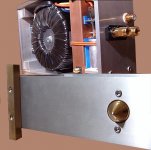
Are there any issues about mounting a toroid vertically in an enclosure...
My planning has left me little alternative.
My planning has left me little alternative.
chipco3434 said:Are there any issues about mounting a toroid vertically in an enclosure...
My planning has left me little alternative.
I don't see any issues with this.
--
Brian
S.C said:Peter's AMP-2 transformer was mounted vertically, and mine too hehe
I like the way he did it too.
--
Brian
Attachments
hi fanatics,
my gainclone based in BrianGT's boards is up and running. Thanks again for the great kit Brian. 🙂 I will send you some pictures later.
One problem remains : I get a humming noise (low frequency) when I connect a device at the input via cinch cable. I used a cd player to test this. With no music playing (stop) there is this hum. As soon as I start playing the hum is gone and the sound is very clean an clear (or very very silent if volume is turned down all the way). If I unplug the input cable completely there is *no* noise. Strange, I tried using different cables, checked grounding, no luck so far. Could a capacitor between signal-in and ground-in improve things? What else might help? Any hints are appreciated.
my gainclone based in BrianGT's boards is up and running. Thanks again for the great kit Brian. 🙂 I will send you some pictures later.
One problem remains
: I get a humming noise (low frequency) when I connect a device at the input via cinch cable. I used a cd player to test this. With no music playing (stop) there is this hum. As soon as I start playing the hum is gone and the sound is very clean an clear (or very very silent if volume is turned down all the way). If I unplug the input cable completely there is *no* noise. Strange, I tried using different cables, checked grounding, no luck so far. Could a capacitor between signal-in and ground-in improve things? What else might help? Any hints are appreciated.So the noise occurs only when CDP is in STOP position. The player has probably some mutin circuit at the output (a relay?) and it's activated when not in use. it may create some ground loops and that's what the noise comes from. Maybe you could check if coupling cap (at the input) helps, anything of 2uF or more.
Thanks for your reply, this is exactly what was going on, using coupling caps solved the problem, now everthing seems to work well.
I just finished the chassis this afternoon, then I put the`pcb and stuff together into the chassis. I checked all the connect and no sight of short, but my left channel 8x-90 mV when I measuring the +/- blinding with 2x 51ohm resistor in parallel. And the right channel have about 45-50mV. When I play the music, the Left channel keep switch on and off, and the music on the left is clearly different from the normal right channel. How can I fix it?
Strange things happen, I made the amp work now after I use my meter to measure the DC V on pin 1 of the chip and the feedback resistor. It work immediatly after I touch it? How come? and my chassis getting really hot now, and it is not because of the heat from the chip but the tansformer part. The heat sink is fine, but the chassis is untouchable. Is it because the transformer's wave heat up the chassis?
S.C said:Strange things happen, I made the amp work now after I use my meter to measure the DC V on pin 1 of the chip and the feedback resistor. It work immediatly after I touch it? How come? and my chassis getting really hot now, and it is not because of the heat from the chip but the tansformer part. The heat sink is fine, but the chassis is untouchable. Is it because the transformer's wave heat up the chassis?
It sounds like you may have a loose solder joint on pin 1 that was pushed into place by touching it with the meter. It would be worth it to resolder that joint I think.
I'm not sure about the heat from the transformer though.
A question on GAIN:
In an active setup, how much difference would different amplifier gain, make, in the overall presentation ?
tweeter : 91 db ( will be reduced to 88 )
tweeter GC : 31 db
m/w sensitivity : 88 db
m/w amp : 29 db
Is reducing the gain on the tweeter amp a necessity ?
cheers,
sunil
In an active setup, how much difference would different amplifier gain, make, in the overall presentation ?
tweeter : 91 db ( will be reduced to 88 )
tweeter GC : 31 db
m/w sensitivity : 88 db
m/w amp : 29 db
Is reducing the gain on the tweeter amp a necessity ?
cheers,
sunil
Measure and listen.
Hello Sunil,
You have options; you can decide if they are necessary.
If I understand the figures you have provided, on "paper" you have an additional 2 dB gain in your tweeter circuit. A solution may be to reduce this.
I would be concerned that what you have on paper is not the same as in your system. Try out what you have by listening or measuring with a microphone before making more system changes. It would be helpful to have some sweep tones to play through your system, particularly around the x-over point.
Besides reducing the amp gain, you have the option of reducing the input signal to the tweeter amp. This may be simpler and would provide the same result.
- Status
- Not open for further replies.
- Home
- Amplifiers
- Chip Amps
- Gainclone building thread based on BrianGT's boards