
CT Transformer Success!!!
Mark,
Success! (At least so far.) Today I connected the PS to one of the amp boards. Using a terminal block I made connections between the amp, a 100K log pot, an old cassette deck as a source, an expendable speaker and my PS.
I turned on the cassette deck and hit play, stuck a finger in the ear that was closest to the speaker and flipped the power switch. No noises from the speaker, no explosions from either the amp or the PS and the magic smoke stayed inside the parts! Not only that but the PS fuse didn't blow. So far so good.
Slowly turning up the volume control I heard music! The Grateful Dead sounding pretty sweet. I let it play for a few minutes at a relatively low volume and when all was well turned it up a bit. It seemed happy there as well so I cranked it a bit more and it happily got louder.
At this point I've only connected one amp board to the PS but I would rate this wiring scheme a success. Tonight I hope to mount both amp boards in a chassis (as I feared they won't quite fit in the one I had planned to use to I've pulled out a slightly bigger box), hook up the power umbilical and the volume pot and listen in stereo. 😀
Variac said:Sherman: THIS IS BIG!!!
I have been tormented because I have center tapped transformers also.
PLEASE continue to keep me informed as you attach the amps to the power supply.
-especially regarding possible explosions and/or sheeets of flame
😀 😉 😀 😉
Mark
Mark,
Success! (At least so far.) Today I connected the PS to one of the amp boards. Using a terminal block I made connections between the amp, a 100K log pot, an old cassette deck as a source, an expendable speaker and my PS.
I turned on the cassette deck and hit play, stuck a finger in the ear that was closest to the speaker and flipped the power switch. No noises from the speaker, no explosions from either the amp or the PS and the magic smoke stayed inside the parts! Not only that but the PS fuse didn't blow. So far so good.
Slowly turning up the volume control I heard music! The Grateful Dead sounding pretty sweet. I let it play for a few minutes at a relatively low volume and when all was well turned it up a bit. It seemed happy there as well so I cranked it a bit more and it happily got louder.
At this point I've only connected one amp board to the PS but I would rate this wiring scheme a success. Tonight I hope to mount both amp boards in a chassis (as I feared they won't quite fit in the one I had planned to use to I've pulled out a slightly bigger box), hook up the power umbilical and the volume pot and listen in stereo. 😀
That's way overkill for the heatsinks. You'll be able to put six GCs in that case!
yes, but they are free and I had "matching" 1/8" plate on the shelf.
Re: -=Sneak Peak=-
Hey, I have seen those Heat transfer pipes at a local supplier for $3 CAD each! 🙂
Antrhony
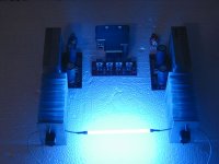
Wardsweb said:Without giving away to many secrets, here is a pic of a work in progress. Realize the light is NOT that bright. It just looks that way because of the camera speed set low to get enough detail from the surrounding area. Yes it's blue.
Hey, I have seen those Heat transfer pipes at a local supplier for $3 CAD each! 🙂
Antrhony
Re: Re: -=Sneak Peak=-
That wouldn't be http://www.activesurplus.com/ , now would it? 😀
Coulomb said:Hey, I have seen those Heat transfer pipes at a local supplier for $3 CAD each! 🙂
Antrhony
That wouldn't be http://www.activesurplus.com/ , now would it? 😀
Re: Re: Re: -=Sneak Peak=-
Yeah, though I saw them in the store. 🙂
Anthony
Wardsweb said:
Yeah, though I saw them in the store. 🙂
Anthony
Mine is feeling lonely in this large box.
An externally hosted image should be here but it was not working when we last tested it.
Kevin Haskins said:Mine is feeling lonely in this large box.
An externally hosted image should be here but it was not working when we last tested it.
Wowowowow Large,arge,rge,ge Box,box,ox,x
🙂
but looking quite beautifulllll!!!!!! Damn, I should have ordered those Cardas posts!!!Mine is feeling lonely in this large box.
Sherman,
Thanks for your report on using center tapped transformers.
I'm glad there were no injuries, or house fires.
If it works for the Greatful Dead, it works for me!!
- now I can boogie on my amp!!!!
I had saved 2 center tapped transformers from an old Proton amp that had serious problems. they appear to be +23v -23v
You just chopped my costs in half!!
Mark
Variac said:Sherman,
Thanks for your report on using center tapped transformers.
I had saved 2 center tapped transformers from an old Proton amp that had serious problems. they appear to be +23v -23v
You just chopped my costs in half!!
Mark
Mark,
I'm glad my experimenting is paying off. All told it only took some time and a couple of blown fuses to get it right.
Please note that I used only one transformer and two bridges. That single transformer will power both channels of my stereo amp. Since my main system is a tube amp with about 4 1/2 watts RMS per channel even this underpowered transformer should easily triple that output.
I didn't get the whole thing running tonight as I had hoped but I have the day off tomorrow so maybe I can finish it then! I'll post pics of the inside of the boxes (PS and amp) when it is running.
Good luck with your amp!
Sherman
THD measurements
I took some measurements using the RightMark software and my soundcard, and attached the THD measurement. This was taken at around 19w into a 8 ohm load. Other power levels were similar. I was very pleased to see that the odd order harmonics were very low as was the total distortion. In fact the highest harmonic was lower than the 120Hz from the power supply!
I'm using Brian's kit parts from the first batch with the 1500uF Panasonic FC and the small blackgate. I will probably experiment with some larger cap values and wondered what experiences people had with doing that. I'm interested in the best sound rather than the best measurement so I am just using the measurements as a tool to help get there.
Attachments
Single PCB gainclone
Hi Peter Daniel and others,
Ever since I bought two of the first gainclone prototypes made by Peter Daniel I have been following this building thread. Being such an incurable minimalist I can't stop wondering if it is any advantage building a complete gainclone on a single PCB? The speaker terminals and inputs would attach directly to the PCB. Wiring is only needed for the transformer.
/Thomas B
Attachments
Re: Single PCB gainclone
I don't think that you would want to have the diodes for the power supply rectification that close to the inputs.
A single board would be interesting looking, but not too versatile. If you look at my gallery, you will see how different all the designs are using the pcbs:
http://www.BrianGT.com/gallery/nigc
--
Brian
Thomas B said:Hi Peter Daniel and others,
Ever since I bought two of the first gainclone prototypes made by Peter Daniel I have been following this building thread. Being such an incurable minimalist I can't stop wondering if it is any advantage building a complete gainclone on a single PCB? The speaker terminals and inputs would attach directly to the PCB. Wiring is only needed for the transformer.
/Thomas B
I don't think that you would want to have the diodes for the power supply rectification that close to the inputs.
A single board would be interesting looking, but not too versatile. If you look at my gallery, you will see how different all the designs are using the pcbs:
http://www.BrianGT.com/gallery/nigc
--
Brian
It would be nice and interesting, but this would limit the application of a single board. People would be forced to use it in one specific way only and this would not allow much creativity.
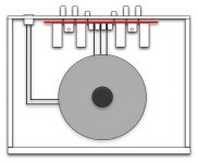
I'm bugging Brian to come up with revised rectifiers board layout, where amp board and rectifiers board are separated by 1/4" standoofs only and PS pads on both boards are aligned so only 1/4 wire lengths connect power from rectifirs to amp board. This is 3 dimentional construction method and has advantage over using a single board for those circuits. I would also use ground plane on rectifier's board to shield amp's circuit from rectifiers.
Then you only connect AC power to that module. As to the RCA input and outputs, a short wire runs would be better that PCB traces, if proper wire is used. Also different kind of binding posts and spacing on them would be allowed this way.
Heres the example of what I'm talking about, but spacing between two boards would be less. As it's now, there is no interference from bridges.
The closest thing I've seen is the Scott Nixon amp kit that has the speaker terminals directly on the board.
This does greatly limit your options on chassis, heatsink and mounting.
An externally hosted image should be here but it was not working when we last tested it.
This does greatly limit your options on chassis, heatsink and mounting.
Brian, if you do a revised board, why not also have the amp boards symetrically on each side of the power board with the chip attachment holes on the outside ends of the whole board. As it is now , only one chip is on the outside. That way if you WANTED to be limited, you could leave the whole board in one piece, and the heatsinks would attach on the ends of the board. If you WANT versitility, you snap the board in pieces....
Not if you leave in the score lines so you could also snap it into pieces exactly as you can now. Of course the traces couldn't continue across the scores, so I guess you still need jumpers across them.....I guess Thomas B wanted the traces to be continuous, yes, that would be limiting- I get it now!!!😀
I think you could combine Peter's and my ideas. The amp boards on each end are identical, it's just that both sides have the chip/heatsink connections on the outside...
P.S. Did you notice that Sherman seems to have come up with a way to use the dual bridge with a center tapped trannie?
It would be nice and interesting, but this would limit the application of a single board. People would be forced to use it in one specific way only and this would not allow much creativity.
Not if you leave in the score lines so you could also snap it into pieces exactly as you can now. Of course the traces couldn't continue across the scores, so I guess you still need jumpers across them.....I guess Thomas B wanted the traces to be continuous, yes, that would be limiting- I get it now!!!😀
I think you could combine Peter's and my ideas. The amp boards on each end are identical, it's just that both sides have the chip/heatsink connections on the outside...
P.S. Did you notice that Sherman seems to have come up with a way to use the dual bridge with a center tapped trannie?
- Status
- Not open for further replies.
- Home
- Amplifiers
- Chip Amps
- Gainclone building thread based on BrianGT's boards