I think they
just use a sharp craft knife and cut the plastic open and peel it off
= my guess
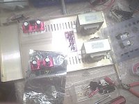
here gc #6
was tired
could not read most of the printing on the pcb'c
did not want to look for implementing 2 trannies in parallel with CT on the powersupply pcb
threw it out
now listening to Oh Brother, where art thou? sound pretty good but still not as good as my 70' Quad 33
playing with Mintek dvd and pioneer speakers right now.
just use a sharp craft knife and cut the plastic open and peel it off
= my guess
here gc #6
was tired
could not read most of the printing on the pcb'c
did not want to look for implementing 2 trannies in parallel with CT on the powersupply pcb
threw it out
now listening to Oh Brother, where art thou? sound pretty good but still not as good as my 70' Quad 33
playing with Mintek dvd and pioneer speakers right now.
Attachments


im feeling left out here since im not using Brians boards 🙁
I should add tho , probably the only reason im not is that They would have ot be shipped across the country, and not worth it as a result 😛
uvodee, i wish my workbench was that neat while work in progress 😛
I should add tho , probably the only reason im not is that They would have ot be shipped across the country, and not worth it as a result 😛
uvodee, i wish my workbench was that neat while work in progress 😛
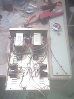
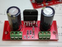
My kit arrived Saturday. Sunday I soldered up one amp board and the PS board. I have a center tapped transformer so I wired it like this- AC1 from transformer to AC1H, center tap from transformer to AC1N and AC2H and AC2 from transformer to AC2N. Powering up I'm getting exactly 25.9V + and -. I haven't connected it to the amp board yet.
The case I intended to use may be a bit too small (a pyramid shaped cigar box). I might be able to use it by redesigning my heat sink. I hope to get the other amp board soldered today and the new heat sink cut to size. Maybe then I can verify that everything fits.
Here is a photo of my PSU and the intended amp case. If I can't fit it into this case I have a larger cigar box that should work with no problem.
I'm really looking forward to getting it operational!
Sherman
Sherman: THIS IS BIG!!!
I have been tormented because I have center tapped transformers also. Brian helped by showing a single bridge scheme for center tapped but OF COURSE we want the double bridge approach everyone else is doing. Especially since I have 2 transformers, so will be making a dual monoblock type approch.
Everything seemed top indicate that the center tapped could be used, but the experts seemed a little concerned. PLEASE continue to keep me informed as you attach the amps to the power supply.
-especially regarding possible explosions and/or sheeets of flame
😀 😉 😀 😉
No photo I can see- I guess it was too big. Would like to see the
PS wiring in a photo, although you described it well....
Mark
Variac said:Sherman: THIS IS BIG!!!
I have been tormented because I have center tapped transformers also.
😀 😉 😀 😉
No photo I can see- I guess it was too big. Would like to see the
PS wiring in a photo, although you described it well....
Mark
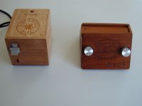
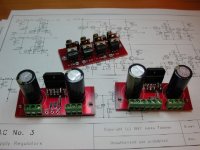
I will post the results here when I actually try to connect it to the amp and turn it on. I'm truly hoping the magic smoke stays inside the components! I actually tried a different approach, making the CT = to the AC1N and AC2N but connecting the grounds together blew the fuse. I think that since the two grounds PG+ and PG- in this new configuration both come from the CT it should work.
Here's the photo.
Attachments
Here's hoping your magic smoke remains where it belongs.
It's a little tricky for me to figure out what the center tap is up to also. I was planning to try it as your first unsuccesful experiment. I've been told that if hooked up wrong, the fuse blowing is the result, so your first results make sense and make us think that you have it "wired" now 😉
I'm jealous that you are so far along...
PMeade said:Just got my breadboard up and running. A couple of questions. I have no on-off switch and upon plugging the amp in I get a rather loud, abrupt noise from the speakers. This is not a "wump" but is sharper in sound. The amp sounds fine and is dead quiet following this. As it is breadboarded, I have no star ground but have connected the two channel grounds together. No input power ground is currently used. Is it the lack of ground causing this or do I look elsewhere? I was surprised to find after 6-7 hours of play that the chips where not even warm to the touch. What's up with that? Why the heatsink if they run this cool? Appreciate any insight.
Paul
Anyone?
I recieved my kit today. I just wanted to say a BIG thank you to Brian. Your Awsome.
Serosmaness.
Serosmaness.
PMeade said:Just got my breadboard up and running. A couple of questions. I have no on-off switch and upon plugging the amp in I get a rather loud, abrupt noise from the speakers. This is not a "wump" but is sharper in sound. The amp sounds fine and is dead quiet following this. As it is breadboarded, I have no star ground but have connected the two channel grounds together. No input power ground is currently used. Is it the lack of ground causing this or do I look elsewhere? I was surprised to find after 6-7 hours of play that the chips where not even warm to the touch. What's up with that? Why the heatsink if they run this cool? Appreciate any insight.
Paul
Well, it all depends on the efficiency of your speakers, the load impedance, and your typical listening volume. With my >90dB efficient Pioneer speakers, the chips are barely above room temperature even after several hours at moderate volume levels. I also have them on a fairly large heatsink that was originally on a pentium II (passive sink). However, when driving a resistive dummy load with a sine wave at full power (78W in my case), the chips do get noticably warm after several minutes, but not begining to approach being uncomfortable to touch. In fact, I am unable to test the amps at max power for long only because of the fact that my dummy load heats up much faster than the chips themselves. However, because the chips will dissipate much more heat at higher volume levels and get extremely hot almost immediately when the output short-circuit protection is activated, a heatsink is pretty much necessary. Also keep in mind that your chip is cool to the touch because of the heatsink. Without it, the chip temperature would be determined by how much heat the chip package can transfer to the air, which is not very much. In fact, you could probably expect a rise ~20°C (rough guess) per watt of thermal power. This will give you very little headroom in terms of output power before the thermal protection kicks in, and naturally, the chip could fail very easily.
If you really want to see if a heatsink is necessary, you could always try running a chip without one, and crank up the volume, but I certainly would not recommend it.

I thought that was probably the case. I am not sure of the efficiency of the speakers as they are old ones I haven't used in 30 years. I didn't want to cook any of my "good" speakers. Any thoughts on the power up noise?
PMeade said:I thought that was probably the case. I am not sure of the efficiency of the speakers as they are old ones I haven't used in 30 years. I didn't want to cook any of my "good" speakers. Any thoughts on the power up noise?
It's hard to say. My best guess would be EM spikes generated by tiny arcs that jump from the outlet to your power plug as you plug it in. I would definitely recommend that you install an AC switch, or at least plug the amp into a power strip with a switch.
I will give the power switch a try. Other than that I am pleasantly surprised with the "little amp that could." As I stated, the speakers I used initially are certainly not my references so it is hard to make any real comparison/claims, however, the sound definitely improved to a significant degree over the first 5-7 hours. I appreciate your insights.
Paul
Paul
I have two lm3875t chips new plus insulators, anyone want to trade them for two lm3875tf's. I know this should go on the trade page but who looks out there.
budwiser said:I have two lm3875t chips new plus insulators, anyone want to trade them for two lm3875tf's. I know this should go on the trade page but who looks out there.
drop me a mail, and I can help you out 🙂
--
Brian
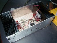
Coulomb said:Well Brian here are a few work in progress pics of my Dainty Amp project. 🙂
I am not sure of the chassis design yet.
Attachments
- Status
- Not open for further replies.
- Home
- Amplifiers
- Chip Amps
- Gainclone building thread based on BrianGT's boards