https://www.facebook.com/reel/1517232922019580?fs=e&s=TIeQ9V&mibextid=0NULKw
its all there if we look…. ’ random’ wizard mode simulation results by sliding things into where they ‘look’ good makes mediocre subwoofers. But when looking for something that already exists using horn response, and finding it, is the 🚀🚀
its all there if we look…. ’ random’ wizard mode simulation results by sliding things into where they ‘look’ good makes mediocre subwoofers. But when looking for something that already exists using horn response, and finding it, is the 🚀🚀
Attachments

Last edited:

Define ‘normal’ ?? 😆Wow, BW posted (#199) a normal pic!
Attachments

And high contrast color scheme is less than "normal" 🤪
I posted an app for him to capture the screens but ohhhh my... You can't teach an old dog new tricks it seems 🤣
I posted an app for him to capture the screens but ohhhh my... You can't teach an old dog new tricks it seems 🤣
I don’t understand why anyone tapers or flares things instead of using constant cross sectional areas in two or three fold quarter wave pipes. You can change the cross-sectional area in the last fold and you can use simple math to which works perfectly every single time to locate the driver.
It’s almost as if you dipped into the horn response algorithm?
At the same time, you have not created all that upper band with (and beyond) craziness, that’s impossible to use or cross over cleanly out of.
Hopefully, Brian Steele follows through and builds one of them. I am quite sure it will become obvious. It works every time and it’s simple. Try it and see, they are EASY for a reason, They follow the existing sound/freq that’s there to use.
it makes a remarkable difference in paraflex models when they tighten things up in this way as well. And given the right TS parameters, those really start to sound good for the same reason.
Last edited:
I don’t understand why anyone tapers or flares things instead of using constant cross sectional areas in two or three fold quarter wave pipes. You can change the cross-sectional area in the last fold and you can use simple math to which works perfectly every single time to locate the driver.
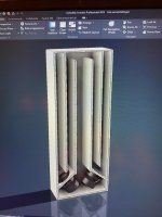
I implement two of your regular post layout and played with them in hornresp and FreeCAD, I played with some different lengths, ratios and cross section areas but I wasn't able to see improvements compared to others design so I quite and didn't complete the models. Maybe Brian can better explore them.
Reducing the cross section area in the last segments helps to damper things, but it will increase air speed, I din't check any value precisely. Specially for TH type this approach will increase the difficult to assembly the driver.
Attachments
It’s not so much there’s an improvement, but there isn’t a discontinuity in the band with at three times the fundamental. Subsequently a flat band with all the way 5 x the fundamental Results in an extremely easy crossover scenario, without crazy slopes, or a bunch of dsp/electronic intervention?
The more we can do with acoustical shapes the less we have to retard with electrical? This is a win-win every time unless everything’s just going to become a sealed box with a DSP connected to a driver that can be molded into anything at some point.
Horn response hints at a lot of things that happen when you collide two separate resonators together that aren’t perfectly sized and of the appropriate length to which they will without issues and once you do that in paraflex in Parallel, you have to be concerned because it’s much more of an issue once you experience it and don’t fix it or pursue, what fine tuning it requires.
this is a matter of sawdust not theories, and until people are building these things there’s not really a fair argument or debate that’s backed with results. But at the same time, if people aren’t building things, and they’re just playing with horn response and asleep, then that group of people slowly become disconnected from what would be helpful as well.
Martin king has addressed many of these things in the past. His mathcad studies are /wheretoo abbreviated to use both sides of the driver inside the enclosure (Higher order qw) Nevertheless, if you take that math and you throw it around in other areas, using g David McBeans program, it still works.
Last edited:
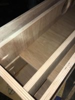
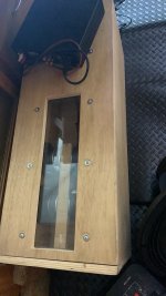
Can a 6.5 driver can be used to "play" experimentally with 1/2 inch cheapest ply just to measure at low power freq response against hornresp Sims?
https://www.parts-express.com/pedocs/specs/295-416--dayton-audio-tcp115-8-specification-sheet.pdf
imagine we’re all using two or four of these in a ‘40hz sub’ and building the same exact enclosure and by the time we all shift through two or three or four different approaches to qw subwoofers in a month or two of weekend fabrication/ repeat we collectively are absolutely a bunch of ’experts’💚 and share notes/data of subjective/objective
That then can be used and proportionally extended into bigger, lower, subwoofers and drivers…. But from the standpoint of quite a few individuals who now clearly understand what other people don’t?
you get these things on point, and then define tuning it’s only left up to a little bit of stuffing or a tiny bit of exit adjustment. If you build a paraflex, how do you use the same exact cross-sectional area throughout the entire design and split the resonator lengths at exactly 3 to one you have the perfect scenario in simulation. In reality, only a tiny bit of adjustment if anything at all needs to be made for whatever reason as long as that is using a cross-sectional area that suits the TS parameters, but more so isn’t excessive to fit the driver perpendicular instead of sideways along the path.
If you create a paraflex, that’s exactly 3 to 1 and sized the same throughout hypothetically, then you also see smoothing the bandwith further is seen by centering the driver(s) positions in the first of what will be ultimately the distance from the clossd end , then shared from both sides. It’s so simple it’s ridiculous and there’s no need to complicate it when these have such profoundly excellent results every time In this way.
find the math of horn response and use it. Does that really need to be in advance center line method used in an enclosure it’s constant cross-sectional area and has barely any folding? What would we learn if we weren’t chasing those little weird details that aren’t necessarily accurate anyhow unless you are forced to because you’re trying to figure out our expansion rate through complex Bends and twists?
I don’t know, but my impedance plots measured and simulated are dead nuts at it. I am folding these in thirds, and not complicating it with all kinds of extra weirdness
Last edited:
It’s not so much there’s an improvement, but there isn’t a discontinuity in the band with at three times the fundamental. Subsequently a flat band with all the way 5 x the fundamental Results in an extremely easy crossover scenario, without crazy slopes, or a bunch of dsp/electronic intervention?
I can complete both models for you in FreeCAD, the Paraflex and the Tapped Horn - TL, in addition just indicate the driver you want to work with so I can set up
Thielle Small parameter in the model and so you can focus only to adjust the dimensions.
Change them according to your math and show us the results, like comparing the phase response from your model to the classic TH-SS or any other consolidate solution. We can create a specific thread to discuss your design advantages but it's important to find a good way to demonstrate it using screenshots. Angled photos and random numbers are not helping much. Even simulating them I can't find what you say.
Let us challenge you and learn with real results.
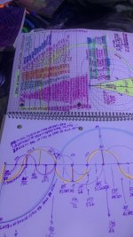
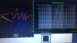
3:1 as measured and as simmed and we don’t have the discontinuity in them as you can see in the white picture sim and measurement
I’m not here to sell anything. This is a fun hobby. Anything more than that and it just becomes a job….. we can all building these things on the cheap and experience the same things collectively. Or we can BS each other forever😝
I’m not here to sell anything. This is a fun hobby. Anything more than that and it just becomes a job….. we can all building these things on the cheap and experience the same things collectively. Or we can BS each other forever😝
Attachments
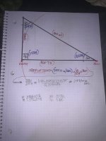
L12 104.72cmI can complete both models for you in FreeCAD, the Paraflex and the Tapped Horn - TL, in addition just indicate the driver you want to work with so I can set up
Thielle Small parameter in the model and so you can focus only to adjust the dimensions.
Change them according to your math and show us the results, like comparing the phase response from your model to the classic TH-SS or any other consolidate solution. We can create a specific thread to discuss your design advantages but it's important to find a good way to demonstrate it using screenshots. Angled photos and random numbers are not helping much. Even simulating them I can't find what you say.
Let us challenge you and learn with real results.
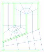
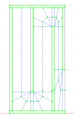
L23 100cm
L34 95.28 cm
s1-s3 (900 cm2)(red highlighted in HR)
S3-s4 (450 cm2)
per driver
corner loaded B&C 18 ds115-4 for example.
Or, for the Dayton audio Ultimax 18 you would change that to 1200 and 600 (each) and extend the length to 125.66, 120 and 114.34cm ?
if you don’t want to nickel and dime the simulation tool to the offse driver entry position for that pressure node at the 3FB frequency then you can just make them all the same length and stuff the area behind the driver until the response doesn’t care either and has flat results through that area all the way to the f5x Fb notch
that’s 21.6-144hz with the b&c and if you wanted to, you could take advantage of that drivers Qes(and a louder, flatter response ) and instead expand(600,600, 1200 cm2) in the last segment and even divided up into vents on both sides the driver?
i have fushion360 versions of this and the 3 fold to one parallel qw pipe with exit @ that interval In short videos.
Attachments
Last edited:
Booger ,
We all do this as a hobby
We learn from each other
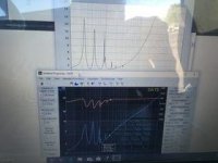
Can you be more specific and show all your hornresp screens ?
Your graphs cell pics lack the necessary optical detail
Share/upload your hornresp txt file so we can see clearly in our own copy of hornresp the complete scenario cause we don't have a clue what you try to show
Lordsansui have a valid point ,so do you agree to cooperate on his methods to replicate or else what you are talking about.
Cause what's the point of building things on the cheap if we can't share them with the community?
We all do this as a hobby
We learn from each other
Can you be more specific and show all your hornresp screens ?
Your graphs cell pics lack the necessary optical detail
Share/upload your hornresp txt file so we can see clearly in our own copy of hornresp the complete scenario cause we don't have a clue what you try to show
Lordsansui have a valid point ,so do you agree to cooperate on his methods to replicate or else what you are talking about.
Cause what's the point of building things on the cheap if we can't share them with the community?
my computer screen is broken from testing speakers in the field and the screen is what it is. I can’t do anything about that it’s about to seperate from the lower half and apologize. Lord sansuis ideas are excellent
Last edited:
Booger,
Sorry about your broken laptop screen
Here comes Lightshoot to the rescue !!!
Install this
https://app.prntscr.com/en/index.html
And paste screenshots directly without using your cell, you save more hassle.
It's quick and fast you just
press the printscr key
Select the area of hornresp with the mouse
Select copy from the side menu
Select your DIY forum post
Press CTRL-V and Voila!!
Instant eye candy!
- Home
- Loudspeakers
- Subwoofers
- Furysub, Apache H15, or Jbell 2' cube