Come to think of it there are only two steps involved in setting up the network for zero volts across the coil using the two adjustment resistors. In step one the emitters are short circuited with the output adjusted for zero volts at the output. This causes whatever differential currents to flow in the short between the emitters, yet the emitters are both at equal potentials. Then when opening up the link the lower adjustment resistor is set for output zero, requiring the error current to be diverted in one of the two paths, coincidentally the emitters would then be at zero potential. This is similar to what Hans did in his analysis varying upper and lower resistors.

I was doing something similar, but transistors were mosfets and I put R-C filter between opamp out and gates, no need for super low Rin with small mosfet. Might be here it would work too if C is large enough to keep AC impedance very low....
Nice to see your awake Drbulji...Again me with uneducated question; isn't referencing bases to virtual ground (eg opamp U9 and U10) output going top feed them opamp output noise?
Besides, who changes carts with preamp on?

So it does work with R-C 🙂
Might be also idea, in the past I did something that looks unique with power amp, here; https://www.diyaudio.com/community/...ttle-fb-160watt-amplifier.412261/post-7672602
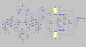
Output is brought to 0v DC (and can be set to any DC value) by servo driving current sources. Bias current is than 100% determined by collector resistors only.
The DC between emitters should always be 0 as on both sides as it is 0V-Vbe, as long as transistors are matched for it. In our case something like this:

Output DC level is adjustable by choosing resistors in V deviders feeding servo opamp.
This is just another idea, I think it would make it very stable from static DC perspective
PS, small capacitor can be added in deviders from outputs, to filter signal and leave only DC being fed to opamp + input
Might be also idea, in the past I did something that looks unique with power amp, here; https://www.diyaudio.com/community/...ttle-fb-160watt-amplifier.412261/post-7672602
Output is brought to 0v DC (and can be set to any DC value) by servo driving current sources. Bias current is than 100% determined by collector resistors only.
The DC between emitters should always be 0 as on both sides as it is 0V-Vbe, as long as transistors are matched for it. In our case something like this:
Output DC level is adjustable by choosing resistors in V deviders feeding servo opamp.
This is just another idea, I think it would make it very stable from static DC perspective
PS, small capacitor can be added in deviders from outputs, to filter signal and leave only DC being fed to opamp + input
J
Missed it so far.
Hans
Interesting thread, nice project.Might be also idea, in the past I did something that looks unique with power amp, here;
Missed it so far.
Hans
We can shake hands.You will notice there my mistake in measurements
Yesterday I also made several sloppy mishaps because not having the peace and trying to do things in a rush. 😊
Hans
I tried to put my daughter to bed when she was two... but she refused to go. She then tricked me into playing poker all night and I lost my car. Now I'm driving a rental that I used to own. Seems the cutest little devils grow up the quickest...🙂 Not for long, my turn to put kid in bed tonight
Second attempt.
This time properly checked and giving no additional noise.
There may be no technically quantifiable reasons but I wanted to avoid electrolytic capacitors, even in the servos. Secondly it doesn't appear necessary if output servo's are an acceptable solution, though I can't remember, was it "Marcelg" that discussed problems as relatable to what I have done using a servo in the RIAA. Perhaps I should read that more carefully.
Your network seems well suited for handling individual lower noise separate transistors, particularly like ZTX851's, and as you pointed out seems can easily handle thermals as well. In rethinking this, to push the envelope in terms of noise performance in the ability to use separates, the following is a preliminary idea that could contain some critical flaws. It also uses a servo because it is doubtful if the output servos have the range to control the variance of separates. I used an LT1013 because it can operate with input signals at the negative rail, having moderate noise output that can be reduced by the division ratio to the base of the input pair. The link at the base is for calibration. H'm... seems the inputs to the LT1013 may need switching (?)....

Last edited:
I’m against any caps in the signal path, but in a servo an elecrolytic has the same function as in the power supply, where you can’t do without.There may be no technically quantifiable reasons but I wanted to avoid electrolytic capacitors, even in the servos.
However your solution with 1R resistors is a nice one and saves on electrolytics.
Now the circuit you propose has to many regulators to my feeling.
You want to keep the DC currents equal in both LTP legs and you want to have a near zero DC offset at the output.
So two parameters to steer, for which you only need two regulators where you now have three.
When discarding the two 50R resistors and the pot between them, you could connect the opamp’s input to both emitters instead.
That part will then take automatically care of the equal DC currents in both legs.
The pot at the top will then be used to get the DC offset to around zero volt.
With one servo however there is always a DC voltage on the Cart lines, but that’s a choice to be made.
When using two isolated transistors, try to match their hfe, because their base currents will flow through the emitters.
So with equal voltages on the emitters it does not automatically mean that the collector currents are the same.
With the ZTX851 having a low hfe, much lower as the Mat02, it is of special concern.
Hans
@Hierfi,
About the impact on the Riaa correction when using a servo, exactly what Marcel described, can be perfectly seen and corrected with your model in LTSpice.
Feed it with an anti Riaa signal and the outcome should be within the borders you have set, in most cases something like +/-0.1dB
Hans
About the impact on the Riaa correction when using a servo, exactly what Marcel described, can be perfectly seen and corrected with your model in LTSpice.
Feed it with an anti Riaa signal and the outcome should be within the borders you have set, in most cases something like +/-0.1dB
Hans
Haven't worked that out in my head yet as common base is supposed to be unity gain. But things get a little convoluted with voltage and current of the cart interacting with the emitters. Things aren't all that clear without any feedback. LTSpice should tell me. I will check the rest out.With the ZTX851 having a low hfe, much lower as the Mat02, it is of special concern.
The reason I wanted to place the inputs of the LT1013 near the negative rail was to keep them away from the emitters for pickup reasons. The issues reduce by resistance division being closer to the negative supply. Just a guess...
Sonic related impact with electrolytics in the power supply depend upon the CMRR. Hence if the network is in perfect balance those sonic issues would be 180dB down in the network, (at least according to LTSpice), being in common mode.
There are things in simulators that it can't reveal because it treats all lines shown on the schematic as singular points. The reality is that they are lines connected often in some convoluted way as unpredictable in the manner of its engagement with the surrounding environment.
Last edited:
Personally don't see problem in using electrolytic if they are large enough, and bit larger than enough. If the impedance at given frequency is 0 there is no theory to prove that distortion can be generated. Of course at LF there will be some small impedance but we (humans) are not so sensitive about LF distortion.
By the way, what is your opinion about my construction to servo drive current sources for getting output at DC target?
And another thing, unfortunately late Scott Wurcer made this design for MM https://www.diyaudio.com/community/...single-ended-phono-preamp.306811/post-5042118.
The LTP can be modified for MC specifications, but second stage with RIAA looks really interesting and innovative.
@Hans, you were participating a lot in that thread, did anyone built that design that you know?
Anyone has opinion about it?
By the way, what is your opinion about my construction to servo drive current sources for getting output at DC target?
I will try to respond tonight when I'm back home.And another thing, unfortunately late Scott Wurcer made this design for MM
Hans
You have to be a bit careful here. Douglas Self carried out a set of measurements in Small Signal Audio Design. The killer is any AC voltage of magnitude greater than 80mV starts to generate distortion products. So there is an objective number to calculate from. If it gets much above 1V, you get distortion approaching 0.1% or more.Personally don't see problem in using electrolytic if they are large enough, and bit larger than enough. If the impedance at given frequency is 0 there is no theory to prove that distortion can be generated. Of course at LF there will be some small impedance but we (humans) are not so sensitive about LF distortion.
Feeding into a 1k load, Self found that to get distortion to be indistinguishable from his Audio Precision test set distortion at 10Hz needed 1,000uF.
Craig
Hi Craig,
Thanks for reminding me to revisit the book. I do agree that taking care is very good way!
What Mr Self is also saying in the same chapter is:

Point is that large capacitor will have no impedance (or negligible voltage across capacitor) and small current in frequency range of interest, and hence no distortion. At very bottom of frequency range some small distortion cannot be observable whatsoever. You mentioned 10Hz, who cares for 10Hz ?
Different story altogether for filter caps, their function is to have variable impedance at frequency of interest. There I have fetish on RIFA 1% extended foil polystyrene, I will always use them until I run out of stock as they are not available any more to buy....
Thanks for reminding me to revisit the book. I do agree that taking care is very good way!
What Mr Self is also saying in the same chapter is:
Point is that large capacitor will have no impedance (or negligible voltage across capacitor) and small current in frequency range of interest, and hence no distortion. At very bottom of frequency range some small distortion cannot be observable whatsoever. You mentioned 10Hz, who cares for 10Hz ?
Different story altogether for filter caps, their function is to have variable impedance at frequency of interest. There I have fetish on RIFA 1% extended foil polystyrene, I will always use them until I run out of stock as they are not available any more to buy....
The problem is that harmonic distortion comes with intermodulation distortion. So if you have frequencies in that ultralow frequency range with significant distortion (from record warps and ripples etc) that will produce intermodulation sidebands in the music content.
See Self, Small Signal Audio Design Ed 2, pages 71-74. Lots of detail there on the process of electrolytical capacitor distortion.
Or the late, great, Cyril Bateman's articles, downloadable from https://linearaudio.net/cyril-batemans-capacitor-sound-articles if you want some light bedtime reading.
Or the late, great, Cyril Bateman's articles, downloadable from https://linearaudio.net/cyril-batemans-capacitor-sound-articles if you want some light bedtime reading.
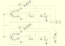
It's a capable circuit with increased PSRR on the negative supply with the two additional transistors with their high collector impedances.By the way, what is your opinion about my construction to servo drive current sources for getting output at DC target?
On the other hand, the two lower transistors will have unequal thermal behavior, so a single current source may improve stability, but this will have impact on the design.
And despite tolerances on resistor values, the collector DC values will still be kept equal, buy CMRR will be affected the higher the deviation from nominal value.
So my preference would be to split the PSRR and CMRR into two separate regulator circuits, one being a servo to keep the currents constant and a pot between collector resistors and positive supply to tune the CMRR.
This was a 4nV/rtHz MM preamp, with current driven Riaa equalization, just as in Hierfi´s design.And another thing, unfortunately late Scott Wurcer made this design for MM https://www.diyaudio.com/community/...single-ended-phono-preamp.306811/post-5042118.
The LTP can be modified for MC specifications, but second stage with RIAA looks really interesting and innovative.
@Hans, you were participating a lot in that thread, did anyone built that design that you know?
Only the 90k9 resistors had to be a bit higher because of the drain impedances in parallel.
The problem is that you will have to match Fets, so you will need a large amount to get the right ones.
At the end a lower S/N will be much harder to achieve.
Basically it's a nice simple design from the previous century, that as far as I know has not been built by anybody but by Scott himnself.
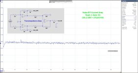
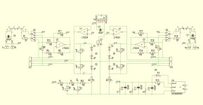
Much more challenging was the basic John Curl design mentioned in the thread, of which I made a more modern differential version having below 0.3nV/rtHz input noise.
Several versions were build, where I sold PCB's and gave support.
See Circuit diagram for the Transimpedance version on a PCB of itself.
A Diff to SE converter plus power supply generator were situated on a motherboard.
Hans
Attachments
- Home
- Source & Line
- Analogue Source
- Fully balanced MC phono preamplifier thoughts