Thanks Hans , and Craig,
Some material to digest you people provided, I have to put my kid to bed again, and in process I'm also gone every time. it will be morning coffee read.
Thanks,
Dražen
Some material to digest you people provided, I have to put my kid to bed again, and in process I'm also gone every time. it will be morning coffee read.
Thanks,
Dražen
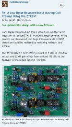
Some interesting results...Feed it with an anti Riaa signal and the outcome should be within the borders you have set, in most cases something like +/-0.1dB
A DC servo control was included in the simulation network with performance to an extent unwarranted in the reality, this using an LT1464 op-amp. Though this device is incredibly inexpensive in simulator form (being less than $0.00US rounded up), it is about $8US in its more robust version. As an aside, bear in mind that the placement of the DC servo at the high level output side works well with matched input pairs, though further thought is required to implement non-matched devices like the lower noise Zetex devices, this for a variety of reasons.
It is expected that a TL082 (at $1US) would be adequate, as this has low enough input bias currents to generate an adequately low DC adjusted output, along with having the unnecessary speed at this point. The servo loop control is slow with its inputs unmoving around ground, hence does not need correction speed more than that of an ox protecting her furlongs (it turns out that's why the ox was chasing down my grandmother who was just trying to do some ploughing).
In the screenshots below the input current was offset slightly using a 3k03 resistor for R9 instead of 3k in the schematic. This resulted in about + 1 volt and - 1 volt on the outputs of the LT1464's with output lines servo corrected to around 5uV on the outputs (these appear shown on the schematic), values well below what is remotely necessary. Of note to consider is that the output correction (in this case +/- 1 volt) is almost directly correlated to the gain set by R6. Meaning that if current is doubled by changing R6 to half its value, this doubles the correction voltage required, all else remaining the same.
With the servo active and in place, the variance in the RIAA looks less than +/-0.025dB (over 20Hz-20kHz). I blame this response entirely on you Hans... as you were the one that gave me those values earlier... although if it appears an excellent result I plan on taking the credit.


The screenshot to the right shows the frequency response shifted and extended from 10mHz to 1kHz to show the servo loop control affect on the RIAA. In this the input level was adjusted to set the output to an arbitrary value of 60dB at 1kHz. The vertical scale to the left was set to begin from 57dB at the bottom, hence becoming the 3dB down point for the DC filter response. This shows an intersection of the frequency response extending to begin at around 70mHz. It should be noted that this high pass frequency response can easily be changed by changing the integration capacitors, that when reduced causes the RIAA response to begin peaking, seemingly could be confirming results of studies by Marcel.
Last edited:

Today there is few new N-channel fets (Ti, Toshiba, InterFET...) in matched dual pairs. Problem remains do to match 2 x P-channels in a decent pair , thats completely right.... It is 4nVsqrHz for MM, but that can be modified by different LTP at input. I'm quite sorry that this was not explored deeper while this great guy was among us....his was a 4nV/rtHz MM preamp, with current driven Riaa equalization, just as in Hierfi´s design.
Only the 90k9 resistors had to be a bit higher because of the drain impedances in parallel.
The problem is that you will have to match Fets, so you will need a large amount to get the right ones.
At the end a lower S/N will be much harder to achieve.
Basically it's a nice simple design from the previous century, that as far as I know has not been built by anybody but by Scott himnself.
I see, thank you for sharing! Seems you took the best of the worlds to cook modern Curl variation and than doubled it for fully differential amp! Great!Much more challenging was the basic John Curl design mentioned in the thread, of which I made a more modern differential version having below 0.3nV/rtHz input noise.
Several versions were build, where I sold PCB's and gave support.
See Circuit diagram for the Transimpedance version on a PCB of itself.
A Diff to SE converter plus power supply generator were situated on a motherboard.
For the reasons based on believes and esthetics, and not facts, hitherto I kind of avoided Curl and Lee designs because of use of NPN with PNP pairs and large electrolytic's.
Somehow I feel more pleasing for eye using 2 matched transistors of the same polarity, as they can be matched well... Only in power output stages there is no much choice but to use N and P pairs...
But that is pure matter of taste, not facts, and taste changes, facts don't 🙂
Going back to electrolytics, I note that in Richard Lee's "Duraglit" two transistor common base MC amp, he increased the capacitors to ground from the bases from 470u to 3,300u precisely for distortion at low frequency reasons.
The beauty IMO of the design that I showed is that you don’t have to match anything at all and that thermal runaway is completely compensated.Somehow I feel more pleasing for eye using 2 matched transistors of the same polarity,
Besides, two matched transistors in a LTP let the noise increase by 3dB, whereas a NPN and PNP on top of each other let the noise drop by 3dB, a difference of a full 6dB.
Turning this into a diff amp, will let the noise increase by 3dB, so compared to a LTP it has still 3dB less noise.
A significant difference when going for the lowest possible noise.
Hans
Hi Craig, I think you refer to Hans's design, actually 3,900 uF. Nevertheless doesn't matter, Modest voltage (like 16V) electrolytics are available in really huge C values.Going back to electrolytics, I note that in Richard Lee's "Duraglit" two transistor common base MC amp, he increased the capacitors to ground from the bases from 470u to 3,300u precisely for distortion at low frequency reasons.
I looked at Cyril's work you sent me, not in many details I admit! Don't have 2edition of D. Self, so I did not check that yet,
Nevertheless, what Cyril Baetman shows is that there is measurable distortion of lytics but in low F range. Than again we people don't hear distortion in bass..... especially under 1%.
Of course it would be better to eliminate it as well, probably just for hygienic reasons only, not that we will hear it.
Anyway, you are right 100% that electrolytic or any huge value capacitor is not ideal, then it is compromise where they help improve more critical components and circuits, then they are worth it I think, Compromises, compromises....
I agree to that even I still need to figure how N and P don't need matching, but that's my problem to figure out.... Then as mentioned earlier, is there a point in hunting absolutely lowest possible noise figure knowing what noise LP + stylus produce?The beauty IMO of the design that I showed is that you don’t have to match anything at all and that thermal runaway is completely compensated.
Besides, two matched transistors in a LTP let the noise increase by 3dB, whereas a NPN and PNP on top of each other let the noise drop by 3dB, a difference of a full 6dB.
Turning this into a diff amp, will let the noise increase by 3dB, so compared to a LTP it has still 3dB less noise.
A significant difference when going for the lowest possible noise.
That was already addressed in some way.. Then as mentioned earlier, is there a point in hunting absolutely lowest possible noise figure knowing what noise LP + stylus produce?
It depends largely on the Cart used.
A 0.15mV Cart will ask for a >10dB quieter amp as a 0.5mV one.
With Cart connected S/N should be a minimum of 6dB above surface noise or =>65dBA
Anything above 75dBA is not bringing any additional benefit.
To keep your amp future proof, you better try to land somewhere in the seventies but <=75dBA.
Hans
J
But when inserted in the signal path, the role of an electrolytic has to be considered in a different and more critical way.
One remark however on this electrolytic topic.
At first I used polymer Oscon capacitors at this 3.9mF spot, and noticed a large amount of 1/f noise.
Not believing that the ZTX’s were to blame, I finally exchanged the caps for Panasonic FM alu versions and the 1/f noise was completely gone as can be seen in the noise plot a few postings ago.
Syn08, another great guy that sadly left us, doubted my findings. But to his big surprise in his Fet input phono amp, where he also used polymer caps, the 1/f noise was reduced significantly down to the unavoidable Fet 1/f noise.
So never use Polymers in low noise designs.
Hans
Keep in mind that this 3.9mF electrolytic must be seen as a power supply reservoir, just like used in the power supply itself where nobody talks about possible distortion problems.Hi Craig, I think you refer to Hans's design, actually 3,900 uF.
But when inserted in the signal path, the role of an electrolytic has to be considered in a different and more critical way.
One remark however on this electrolytic topic.
At first I used polymer Oscon capacitors at this 3.9mF spot, and noticed a large amount of 1/f noise.
Not believing that the ZTX’s were to blame, I finally exchanged the caps for Panasonic FM alu versions and the 1/f noise was completely gone as can be seen in the noise plot a few postings ago.
Syn08, another great guy that sadly left us, doubted my findings. But to his big surprise in his Fet input phono amp, where he also used polymer caps, the 1/f noise was reduced significantly down to the unavoidable Fet 1/f noise.
So never use Polymers in low noise designs.
Hans
Hello Canada, I mean Hierfi! Whats your real name anyway?
Hope you are not all frozen there as normally 🙂
We are all interested in your progress, Oki, it is actually me who is interested, cant speak for the world, I'm not Trump thanks god.
Hope you are not all frozen there as normally 🙂
We are all interested in your progress, Oki, it is actually me who is interested, cant speak for the world, I'm not Trump thanks god.
Its Gerrit... but don't tell anyone
This is the only warm day seemingly left... so I have a reservation to put some golf balls to bed in the woods...
I have been doing some experiments with Crazy gluing some ZTX's together but need to work on this a little later... along with some more ideas for the tracking. Its a problem to keep it simple... though perhaps with some further help from Hans in using LTSpice this seems could go much faster.
this sounds goooood!This is the only warm day seemingly left... so I have a reservation to put some golf balls to bed in the woods...
Look, they are pretty flat, as before done with Phiillips BC transistors, I would gently sand flat surface, a bit of Bison liquid metal epoxy, tight together. Optionally later put some thermal paste on assembly, wrap up all together tight with strip of copper, and zip tie or shrink film... That should do as good as possible for thermal bonding 🙂I have been doing some experiments with Crazy gluing some ZTX's together but need to work on this a little later
This is another approach to an MC gain stage https://proaudiodesignforum.com/forum/php/viewtopic.php?f=7&t=1179
The commercial incarnation of this is here https://ka-electronics.com/shop/index.php?route=product/product&path=66&product_id=121
But you apparently can buy a bare board and build it yourself.
Reason this rung a bell in terms of the above post is that he sells ZTX851 pairs too glued into a dome nut https://ka-electronics.com/shop/index.php?route=product/product&path=65&product_id=118
He also does a balanced RIAA stage too, described in detail here https://www.proaudiodesignforum.com/forum/php/viewtopic.php?f=7&t=753
And also available complete or as a bare board https://ka-electronics.com/shop/index.php?route=product/category&path=66
I have not tried any of these designs, neither have I any interest in KA. But I am intrigued by his approach.
This is another approach to an MC gain stage
Attachments
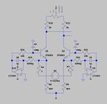
Hi Hans,So my preference would be to split the PSRR and CMRR into two separate regulator circuits, one being a servo to keep the currents constant and a pot between collector resistors and positive supply to tune the CMRR.
Don't think matching 2 resistors is so difficult as matching 2 transistors. I hear your point nevertheless, installing small value pot is not a hassle.. Here are two versions of making LTP doing what it's supposed to do ideally:
First is just added pot at V+ collector resistors to match them
Second, since we have matching pot for collector resistors, we can delete one side of servo , and also one current source:
Is this what you ment? PS sorry for poor scans, I will make dwg next time
No, this is what I meant.
1) Equalising the two emitter voltages at zero volt, to stabilize the LTP currents and make them independent for thermal runaway.
2) Pot at the top to tune the CMRR.
When pot set for best CMRR, both positive and negative PSRR will be below 90dB and CMRR below 65dB
Then two Hierfi servos can be paced in the AD844's output lines.
Hans
Attachments
Ok, got it, even I did not grasp why to get rid of servo-ed current sources yet.No, this is what I meant.
1) Equalising the two emitter voltages at zero volt, to stabilize the LTP currents and make them independent for thermal runaway.
2) Pot at the top to tune the CMRR.
When pot set for best CMRR, both positive and negative PSRR will be below 90dB and CMRR below 65dB
Then two Hierfi servos can be paced in the AD844's output lines.
@Hierfi, seems we will servo out the hell of this design 🙂, 2 servo opamps in ltp + another 2 in your current RIAA
The servo’s on the current sources are not discarded, on the contrary.Ok, got it, even I did not grasp why to get rid of servo-ed current sources yet.
The two servos in my proposal keep the emitters at zero volt causing the current in the two emitter resistances exactly identical just as two perfectly matched current sources, independent of the used transistors.
That’s why PSRR also improved significantly.
Hans
- Home
- Source & Line
- Analogue Source
- Fully balanced MC phono preamplifier thoughts