Rcart influences gain, but output from generator is jus as important.1. dis-balance in Rsource from cart coils will directly make dis-balance in L and R channel gain. I googled a bit on subject of cart coil R measurements, this is not well covered subject at all. Some measurements are taken, guy from Shure stated that up to 5% difference is acceptable (probably referring to MM), someone else said that 10 Ohm is good difference, my expensive Benz has 7% difference (3 Ohm). In any case thing to consider and measure cart R, raw outputs and preamp outputs before concluding set up is ok.
When Rcart differs by 10% but generator output differs by 10% in the opposite direction, voltage output from the SSM will be identical in the transimpedance mode.
So you will have to measure both, not just the resistance.
I would say 3% output difference at 1Khz@5cm/sec will be unnoticeable.
The That1570 having a gain adjustment option in a transimpedance phono amp application could certainly be a bonus for adjusting imbalance or when changing of Carts.2. There is limitation in lowest cart R. Most of these mic amps are not tested for gains above 60db. For SSM2017-2019 that would be Rg= 10 Ohm, so chart R cannot be lower than that, unless we go in unexplored gains over 60db.
THAT1512 has Rf of 2k5 (instead of 5k) which allows for R cart of only 5 Ohm for 60db gain.
Than there is THAT1570 that has all 3 feedback resistors external. Disadvantage is of course that we lose 2 Rf being laser matched on die and need to maliciously match 2 resistors, but advantage is that we can choose Rf 's to our taste , needs for gain and complementing used Rcart.
When using 0.1% resistors will keep CMRR at ca. 60dB and 0,01% at ca 80dB.
Hans

Yes Hans, agree to all.
Particularly funny that gain dis ballance could actually correct cart channel output disbalance
Particularly funny that gain dis ballance could actually correct cart channel output disbalance

Hello Canada, you are alive 🙂 It was quiet without you!
As so far I know, don't thing paralleling for common base is needed, for common emitter yes.
As so far I know, don't thing paralleling for common base is needed, for common emitter yes.
THAT1570, (actually valid version is THAT1580 as I have just seen on their site) with its differential outputs and external feedback resistors could actually be silver bullet solution that would fit all.
In the meantime I was playing with kind of decomposing of SSM mic amp, to make it semi discrete and adjustable for different charts.
Off subject; for some reason, I like diagrams that are symmetrical vertically, so I can draw vertical line-dot-line in the middle. Its probably because human perception of esthetics, all creatures including us are built like that (ok, amoeba might be not) .

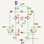
As so far I came to nested feedback amp. 2 op-amps in diff mode making 40db gain through RG2 and Rf + and -, while overall gain is set to 60db by Rg1 ad Ff1 + and -. That leaves 20db for LTP to amplify. Also figured that for 20db LTP doesn't need much voltage, so reduced PS to +- 6V. Since idea is to power from 2x 18V LiIon batteries, 6 volts leaves massive room for super regulation.
This is unfinished and unrefined, so don't spend too much time looking at it (except if you also do like symmetry 🙂)
Nevertheless what was keep coming back is Demrow - Kirkwood design that I first seen in hifisonix overview of MC designs....

@mediatechnology For some reason it skipped me that the Man himself published his latest design of post # 38 of this thread, I think I was busy that week and couldn't follow, but still shame on me!
I turned this idea upside down (PNP instead of NPN transistors) and modified my diagram so it can be easily compared:

First, so many components and adjustments : gone! No current sources, no PS for LTP.
These opamps set new meaning of word multitasking, they at the same time:
It is quite ingenious, wonder why it was not used and discussed more in DIY?
In the meantime I was playing with kind of decomposing of SSM mic amp, to make it semi discrete and adjustable for different charts.
Off subject; for some reason, I like diagrams that are symmetrical vertically, so I can draw vertical line-dot-line in the middle. Its probably because human perception of esthetics, all creatures including us are built like that (ok, amoeba might be not) .
As so far I came to nested feedback amp. 2 op-amps in diff mode making 40db gain through RG2 and Rf + and -, while overall gain is set to 60db by Rg1 ad Ff1 + and -. That leaves 20db for LTP to amplify. Also figured that for 20db LTP doesn't need much voltage, so reduced PS to +- 6V. Since idea is to power from 2x 18V LiIon batteries, 6 volts leaves massive room for super regulation.
This is unfinished and unrefined, so don't spend too much time looking at it (except if you also do like symmetry 🙂)
Nevertheless what was keep coming back is Demrow - Kirkwood design that I first seen in hifisonix overview of MC designs....
@mediatechnology For some reason it skipped me that the Man himself published his latest design of post # 38 of this thread, I think I was busy that week and couldn't follow, but still shame on me!
I turned this idea upside down (PNP instead of NPN transistors) and modified my diagram so it can be easily compared:
First, so many components and adjustments : gone! No current sources, no PS for LTP.
These opamps set new meaning of word multitasking, they at the same time:
- provide low noise high gain amplification, that's as usual
- provide current sources for LTP
- Eliminate PS V+
- servo collectors DC to be equal
- on top their outputs are pulled in class A by constant DC current
It is quite ingenious, wonder why it was not used and discussed more in DIY?
Attachments
Hello Canada, you are alive 🙂 It was quiet without you!
Now that LTSpice is working I'm spending much more time fiddling.... instead of posting...
I'm currently working on an SE I/O MC preamp that I might start a thread on later ... so it isn't applicable here. As so far I know, don't thing paralleling for common base is needed, for common emitter yes.
As so far I know, don't thing paralleling for common base is needed, for common emitter yes.
I believe it matters for common base too Drbulj. Ultimately I want to get back to advancing a balanced current mode I/O MC preamp that is working without global feedback on a differential pair. This seems more important when using discrete devices than for integrated packages, hence plan on continuing in this regard. Don't know yet what is best.
Hello,
No much comments on my ideas of front end. That is fine as my main conclusion is that first stage of amplification should be tailor made for cartridge, not only for specific model, but for specific unit at hand:
Each coil Resistance should be measured as well as each L and R coil V output. Then gain setting can be made .
At the moment I don't have cartridge to be happy with. My Benz Ruby is on ebay, whoever has under 2000€ to have new Ruby 2 open air (after my cart price + total factory rebuilt) will have new high end cart for that money.
I am hoping to sell it and buy 500 to 1000 € new piece.... When this trade is done I can do more contemplation on front end.
Nevertheless I studied more datasheet of that THAT 🙂 1580, apparently it has limitations in gain setting resistors; they say Rf has to be over 2k. Still, if 60db gain is wished for, that limits Cart R to 4 Ohm, which will cover almost all cartridges. I'm talking in trans-impedance mode.
Another lovely thing about this mic preamp is extremely small form factor. To get gain from cart to "line level" or ready to be passively equalized (or to be digitally recorded for later RIAA equalization), only 2 chips, 4 resistors and 4-6 decoupling caps are needed.
I throw these chips and other components in PCB program and printed. This is the size of the circuit that can be mounted directly on tonearm head, reducing wiring from cart to preamp to some 10-20 mm of wire and adding couple of grams to tonearm mass (which is not necessarily bad).... Kind of thinking that Mark Tillotson has in his inside tube preamp. Even his is single ended (and will benefit more from close coupling) and this one is fully differential.
Think this is the ultimate do for eliminating all unwanted signals messing up with our phono play.

One laborious thing needed is that with this set up is that now 7 wires are needed in the tonearm (not 5 that we have) . 2 more wires are obvious requirement for amps PS. But than again, its DIY, if anyone we can rewire tonearm 🙂
No much comments on my ideas of front end. That is fine as my main conclusion is that first stage of amplification should be tailor made for cartridge, not only for specific model, but for specific unit at hand:
Each coil Resistance should be measured as well as each L and R coil V output. Then gain setting can be made .
At the moment I don't have cartridge to be happy with. My Benz Ruby is on ebay, whoever has under 2000€ to have new Ruby 2 open air (after my cart price + total factory rebuilt) will have new high end cart for that money.
I am hoping to sell it and buy 500 to 1000 € new piece.... When this trade is done I can do more contemplation on front end.
Nevertheless I studied more datasheet of that THAT 🙂 1580, apparently it has limitations in gain setting resistors; they say Rf has to be over 2k. Still, if 60db gain is wished for, that limits Cart R to 4 Ohm, which will cover almost all cartridges. I'm talking in trans-impedance mode.
Another lovely thing about this mic preamp is extremely small form factor. To get gain from cart to "line level" or ready to be passively equalized (or to be digitally recorded for later RIAA equalization), only 2 chips, 4 resistors and 4-6 decoupling caps are needed.
I throw these chips and other components in PCB program and printed. This is the size of the circuit that can be mounted directly on tonearm head, reducing wiring from cart to preamp to some 10-20 mm of wire and adding couple of grams to tonearm mass (which is not necessarily bad).... Kind of thinking that Mark Tillotson has in his inside tube preamp. Even his is single ended (and will benefit more from close coupling) and this one is fully differential.
Think this is the ultimate do for eliminating all unwanted signals messing up with our phono play.
One laborious thing needed is that with this set up is that now 7 wires are needed in the tonearm (not 5 that we have) . 2 more wires are obvious requirement for amps PS. But than again, its DIY, if anyone we can rewire tonearm 🙂
Seven wires is getting to be an issue for mechanical compliance and reliability (make the wires thinner and they become less robust to wear/damage). Why not go further and only bring in power on 2 wires, and transmit the signal wirelessly or optically - you'd need a suitable ADC maybe at the pivot end of the arm...
Alternatively think along the lines of phantom power for microphones, which use 3 wires for both power and signal, just add one more wire for stereo and you are at 4 wires again.
Alternatively think along the lines of phantom power for microphones, which use 3 wires for both power and signal, just add one more wire for stereo and you are at 4 wires again.
Hi Mark,Seven wires is getting to be an issue for mechanical compliance and reliability (make the wires thinner and they become less robust to wear/damage). Why not go further and only bring in power on 2 wires, and transmit the signal wirelessly or optically - you'd need a suitable ADC maybe at the pivot end of the arm...
Alternatively think along the lines of phantom power for microphones, which use 3 wires for both power and signal, just add one more wire for stereo and you are at 4 wires again.
Thanks for comment, it is all truth and will work.
What we discuss is listening to LP's in analog form, having "line" level output (I put it in brackets as it is before RIAA and 40 db difference exists in dynamic range between HF and LF as seen by ADC) is just additional benefit if from time to time one wants to archive rare LP. But then I would use one of many available pro ADC's from good sound-card. To build ADC inside loop at tonearm would dedicate this set up for digitalizing which is not general idea here.
Phantom power is an idea, but with huge downsides: it necessitates 2 signal coupling capacitors and removes possibility for front-end amp PS decoupling capacitors, plus adds big PS series resistance .
Considering that alternative is just 2 more wires in armtube (for V+V- PS), I'm not sure that this is not better option.
Nevertheless that also depends on arm, some are easy to add wires, some impossible. Also in fully balanced design we discuss here, benefit of reducing cable for another 10" would probably not be noticed due to about 80db CMMR. Installing amp under arm fixing point would be as good most likely.
I just wanted to highlight that these chips can make viable on arm head preamp too, due their small form factor and minimum external components requirements.
Cheers,
Dražen
Front end for myself will need to wait for appropriate new cartridge. But in meantime would like to reflect on the rest of preamp. Much easier part, passive anti RIAA and final gain stage. For myself, I have decided to built new complete preamp, where RIAA and final stage will be inside of it. That way I can choose different front end amps matching cartridge and choosing where to place them, but keeping RIAA and post amp the same inside preamp.
First stage front end (when decided upon) I will built into the turntable, or even into tonearm.... to be seen. This stage brings signal to serious levels and avoids many considerations of wiring between TT and preamp.
In addition, having RIAA in the preamp allows for possibility of modifying equalization. I only have about 50 original and reissued records from before 1950's mostly early jazz recordings before WW2, non of them has RIAA eq, but god knows what, DECCA or whatever, having adjustable RIAA (if no other issues are created) could make those records play as they are meant to be....
Nevertheless coming back to basic RIAA as first step :
Assuming that first stage is delivering low output impedance balanced signal , flat from cart,at kind of ref. line level:
HF at around 3V RMS
MF at around 300mV RMS
LF at around 30mV RMS
Than following circuit could be as follows:

For anti RIAA I constructed network with my favorite 1% RIFA extended foil polystyrene capacitors, with values that I have. Resistors I did not create yet, but that will be lesser problem to do.
Questions:
1. Is this one stage passive anti RIAA filter best we can do, or to split HF and LF poles in 2 different stages?
2. As so far I used only one capacitor as C2, without middle ground connection. However lately I have seen on tubecad site that its better to couple ground in the middle as shown on picture. This doubles C2 capacitor size... Does it makes sense to include ground there as Brodsky suggests? Snapshot from his site:

If no issue with removing ground from C2 middle, that would reduce difficult to source capacitors use, and PCB size.....
3. In example I used lowest possible impedance for eq filter, calling for larger capacitors and lower R than usual (R1 in my case 3k394). Any pitfalls you see in such approach, is it better to use more common R1 = about 20k and more, and correspondingly smaller caps?
4. Final stage naturally needs to deal with high Rsource, calling for jfet inputs. I did not use it before but see many are praising "new" OPA2828 for such things. Any comment on this, or better second stage recommendations?
- not a question but comment, while we have it, simple gain setting can be done here. I assume that min gain is 20db to compensate 1kHz loss of passive Riaa, but up to 40db will be nice depending what we do in first stage at the cartridge. I put few resistors but did not elaborate yet...
5. And finally on PS. I'm planning on +-18V nominal LiIon batteries. They have immeasurable noise and huge current capability, however V-PS will vary for few volts from fully charged to close to empty. Since these are analog circuits I thing that will not matter much. I think any regulator will just result in noise creation. Also not sure if any extra capacitors are needed except some COG decouplers at chip pins?
Really appreciate your views and comments!
Cheers,
Dražen
First stage front end (when decided upon) I will built into the turntable, or even into tonearm.... to be seen. This stage brings signal to serious levels and avoids many considerations of wiring between TT and preamp.
In addition, having RIAA in the preamp allows for possibility of modifying equalization. I only have about 50 original and reissued records from before 1950's mostly early jazz recordings before WW2, non of them has RIAA eq, but god knows what, DECCA or whatever, having adjustable RIAA (if no other issues are created) could make those records play as they are meant to be....
Nevertheless coming back to basic RIAA as first step :
Assuming that first stage is delivering low output impedance balanced signal , flat from cart,at kind of ref. line level:
HF at around 3V RMS
MF at around 300mV RMS
LF at around 30mV RMS
Than following circuit could be as follows:
For anti RIAA I constructed network with my favorite 1% RIFA extended foil polystyrene capacitors, with values that I have. Resistors I did not create yet, but that will be lesser problem to do.
Questions:
1. Is this one stage passive anti RIAA filter best we can do, or to split HF and LF poles in 2 different stages?
2. As so far I used only one capacitor as C2, without middle ground connection. However lately I have seen on tubecad site that its better to couple ground in the middle as shown on picture. This doubles C2 capacitor size... Does it makes sense to include ground there as Brodsky suggests? Snapshot from his site:
If no issue with removing ground from C2 middle, that would reduce difficult to source capacitors use, and PCB size.....
3. In example I used lowest possible impedance for eq filter, calling for larger capacitors and lower R than usual (R1 in my case 3k394). Any pitfalls you see in such approach, is it better to use more common R1 = about 20k and more, and correspondingly smaller caps?
4. Final stage naturally needs to deal with high Rsource, calling for jfet inputs. I did not use it before but see many are praising "new" OPA2828 for such things. Any comment on this, or better second stage recommendations?
- not a question but comment, while we have it, simple gain setting can be done here. I assume that min gain is 20db to compensate 1kHz loss of passive Riaa, but up to 40db will be nice depending what we do in first stage at the cartridge. I put few resistors but did not elaborate yet...
5. And finally on PS. I'm planning on +-18V nominal LiIon batteries. They have immeasurable noise and huge current capability, however V-PS will vary for few volts from fully charged to close to empty. Since these are analog circuits I thing that will not matter much. I think any regulator will just result in noise creation. Also not sure if any extra capacitors are needed except some COG decouplers at chip pins?
Really appreciate your views and comments!
Cheers,
Dražen
Hi Dražen
I think the author of suggesting to use two caps with a gnd connection in the middle is contradicting himself by saying that this will not be noticed in LTSpice because both caps will be exactly equal.
Using a single cap will never have a matching problem, but in LTSpice it is very easy to give two caps slightly different values, which will without a doubt worsen CMRR.
I won't even try it.
There's not that much against using one passive filter for the whole Riaa correction other than making the tuning a bit more difficult compared to splitting the 75usec from the 3180 and 318usec, because tuning resistors to given caps is way easier than also having to match caps. for LF and HF.
The other reason to split would be the large attenuation with one passive filter, possible bringing again additional noise into the equation.
Within a rather large range it doesn't matter whether small resistors and large caps or large resistors and small caps, as long as you consider noise contribution and costs.
I also heard lots of positive reactions on the OPA828 which probably could be seen as my favorite, but now hideously expensive OPA627, but I would opt the avoid the 1uF caps. Try to make it as DC coupled as possible, eventually by using servo's when needed. The best cap is no cap.
Batteries are very good in feeding phono amps, but in case of doubt you could consider adding very low noise regulators behind the battery like the LT3042 and the LT3093, but this can only be decided upon when listening between the two options, without and with regulator.
I personally prefer sound with regulator after a battery because of better bass and less wooly high frequencies, but this is of course a very subjective opinion.
Hans
Its not usual to have more than 20dB or so gain per stage with opamps due to the rise in distortion and fall in bandwidth and fall in PSRR at higher closed-loop gains - you simply add another stage. Certainly 40dB in one stage could have issues for a generic audio stage.- not a question but comment, while we have it, simple gain setting can be done here. I assume that min gain is 20db to compensate 1kHz loss of passive Riaa, but up to 40db will be nice depending what we do in first stage at the cartridge. I put few resistors but did not elaborate yet...
Here there is a 30dB gain stage, then ~14dB loss (at 1kHz), then 30dB gain again for about 46dB total. 30dB is about as high as its wise to go, and having that much gain in the first stage helps with noise performance of course.
One of the advantages of using the RIAA network in the first stage feedback network is there is no loss for later stages to have to make up with more gain, but it can mean very high closed loop gains for the first stage, but crucially for RIAA this only happens at low frequencies where there is more open-loop gain available, so it is not as bad as it could be.
I had a go at figuring out a gain structure for a multi-stage RIAA here: https://www.diyaudio.com/community/threads/can-an-opamp-mm-phono-preamp-be-blamefree.401679/ - admittedly not differential, nor for MC, but the ideas should still work. In particular the plots in post #3 show the FR's after each stage.
Hello people, thanks for very good comments!
The values I got have worst single component deviation from ideal RIAA of 0.025% and that is R! that can easily be further tuned by parts tolerances, that will be perfect:

Finally I started to make a PCB, for my project idea is to make one larger PCB that will be pretty empty and accommodate PS traces, eventually couple of regulators that can be bypassed.
On top of that board I will input selector for 3 different front ends, riaa filter and final stage, all on separate smaller boards
so they can be taken out and replaced simply, when I change my mind again or want to test something.
Here are first layouts of 2 PCB's from above diagram. Did not have to play with signal GND as in this circuit there is almost none 🙂
However OPA2828 form factor prohibits me to make own PCB 😡 Little craft fun stolen....

Ok, this makes life much easier. I made new layout and saved 6 valuable capacitors !I think the author of suggesting to use two caps with a gnd connection in the middle is contradicting himself by saying that this will not be noticed in LTSpice because both caps will be exactly equal.
Using a single cap will never have a matching problem, but in LTSpice it is very easy to give two caps slightly different values, which will without a doubt worsen CMRR.
I won't even try it.
There's not that much against using one passive filter for the whole Riaa correction other than making the tuning a bit more difficult compared to splitting the 75usec from the 3180 and 318usec, because tuning resistors to given caps is way easier than also having to match caps. for LF and HF.
The other reason to split would be the large attenuation with one passive filter, possible bringing again additional noise into the equation.
Within a rather large range it doesn't matter whether small resistors and large caps or large resistors and small caps, as long as you consider noise contribution and costs.
The values I got have worst single component deviation from ideal RIAA of 0.025% and that is R! that can easily be further tuned by parts tolerances, that will be perfect:
For the moment I keep coupling capacitors, I have 4 huge extended foil 10uF pieces just waiting for this, don't think they would harm any. Even you are right, no cap is best cap..... Will see if its worth doubling otherwise mini circuit. I will also see later if DC can be eliminated in first stage. OPA828 at 20db will not add much DC if its not already there ...I also heard lots of positive reactions on the OPA828 which probably could be seen as my favorite, but now hideously expensive OPA627, but I would opt the avoid the 1uF caps. Try to make it as DC coupled as possible, eventually by using servo's when needed. The best cap is no cap.
Yes, and probably not ever needed neither, I'll just keep possibility to increase gain as it just cost an jumper and resistor, but not to 40dbIts not usual to have more than 20dB or so gain per stage with opamps due to the rise in distortion and fall in bandwidth and fall in PSRR at higher closed-loop gains - you simply add another stage. Certainly 40dB in one stage could have issues for a generic audio stage.
Thanks, I went through your thread, nice. However me and this thread are kind of stuck to passive eq, I was more thinking to move one pole after OPA 2828, not to use it in feedback....I had a go at figuring out a gain structure for a multi-stage RIAA here: https://www.diyaudio.com/community/threads/can-an-opamp-mm-phono-preamp-be-blamefree.401679/ - admittedly not differential, nor for MC, but the ideas should still work. In particular the plots in post #3 show the FR's after each stage.
Finally I started to make a PCB, for my project idea is to make one larger PCB that will be pretty empty and accommodate PS traces, eventually couple of regulators that can be bypassed.
On top of that board I will input selector for 3 different front ends, riaa filter and final stage, all on separate smaller boards
so they can be taken out and replaced simply, when I change my mind again or want to test something.
Here are first layouts of 2 PCB's from above diagram. Did not have to play with signal GND as in this circuit there is almost none 🙂
However OPA2828 form factor prohibits me to make own PCB 😡 Little craft fun stolen....
Regarding my previous post, I'm happy with RIAA filter, but still not with final stage...
These HVSSOP micro mini packaged OPA2828 are getting me.... I'm thinking to pay more money and replace them with 2 x single OPA828 that at least comes in SOIC, than I can craft my own board....
Any other recommendation for dual low noise jfet op amp that comes in DIL or SOIC (please no OPA2604 neither OPA2134, these I know and dislike sound kind off). Friend is for example very found of ADA4625, but that's again single amp, so single OPA828 will do too....
Or, anyone knows where to get good adapter board for HVSSOP to DIL 8?. I looked on internet, tons of stuff but none with thermal pads or provision for decoupling PS caps...
Than again, it could be better to skip 2 opamp differential configuration and use cross coupled 2 INA's, something similar as I use as front end with 2 x SSM2017.
This will ensure better symmetry between +and- signals and remove any DC if it is there (and DC will be there as first stage has huge gain).

But than again, what INA would qualify, low noise, audio bandwith jfet input? These are also scarce, INA110 or INA111 might-be? Any thoughts here?
These HVSSOP micro mini packaged OPA2828 are getting me.... I'm thinking to pay more money and replace them with 2 x single OPA828 that at least comes in SOIC, than I can craft my own board....
Any other recommendation for dual low noise jfet op amp that comes in DIL or SOIC (please no OPA2604 neither OPA2134, these I know and dislike sound kind off). Friend is for example very found of ADA4625, but that's again single amp, so single OPA828 will do too....
Or, anyone knows where to get good adapter board for HVSSOP to DIL 8?. I looked on internet, tons of stuff but none with thermal pads or provision for decoupling PS caps...
Than again, it could be better to skip 2 opamp differential configuration and use cross coupled 2 INA's, something similar as I use as front end with 2 x SSM2017.
This will ensure better symmetry between +and- signals and remove any DC if it is there (and DC will be there as first stage has huge gain).
But than again, what INA would qualify, low noise, audio bandwith jfet input? These are also scarce, INA110 or INA111 might-be? Any thoughts here?
OPA1656? https://www.ti.com/lit/ds/symlink/opa1656.pdfAny other recommendation for dual low noise jfet op amp that comes in DIL or SOIC
Hello, I'm glad you are back here!OPA1656
Great specs! and good price too. Did you listen to it in such application (approx 20db gain)?
By the way, sorry I missed your early post here with flat MC amp, later I came to that design from different sources and angles, and only later realized you elaborated that in many details. Very very smart design!
I will order a PCB from your site, already measured new fascia to quick fit neutrik and your board directly in TT with 2 screws, its 8 cm wide, right?
No point to me to design new board when you did it already.
So daft when I must quote myself 😵 This exists as dual opamp too.Friend is for example very found of ADA4625, but that's again single amp,
Thanks!Hello, I'm glad you are back here!
Great specs! and good price too. Did you listen to it in such application (approx 20db gain)?
By the way, sorry I missed your early post here with flat MC amp, later I came to that design from different sources and angles, and only later realized you elaborated that in many details. Very very smart design!
I will order a PCB from your site, already measured new fascia to quick fit neutrik and your board directly in TT with 2 screws, its 8 cm wide, right?
No point to me to design new board when you did it already.
I haven't listened to the OPA1656 but Vicktor uses it in his superb oscillator. I've been meaning to have Brown Dog make me some on DIP adapters.
The MC board is 8 cm x 10.5 cm.
I recently started using 0.1% resistors in the locations that affect CMR rather than hand-selected them and will be updating the BOM and schematic in a couple of days.
There is an RIAA EQ board available as well based on the original John Roberts RIAA section. I made it jumper-selectable to also provide Inverse RIAA for cutting and instrumentation. My clients for the boards are mostly mastering/vinyl cutting and transfer/restoration. I do have one modern lathe manufacturer using them.
I started out testing paralleled THAT1512's but when the late Brad Wood (aka bcarso) alerted me to the ZTX851 they were so much better and lower cost I abandoned using mic preamp ICs.
I owe a lot to Hans for his suggestions and sims to improve on the first version's servo. We got the 19:20 kHz IM down to the instrumentation residual.
Merry Christmas to all!
In the meantime I managed to open slot in TT to accommodate preamp, some pictures in TT thread
Further on Ortofon test record, visited my friend with completely different TT and run that LP.
System:

For measurement I used lowly Behringer UMA 202 sound card just as it has RCA inputs and I had no time preparing RCA to TSR cables
Measurements are after preamp (so RIAA equilized) as this time I did not have mic preamp at hand.
On 1Khz THD,
New ZYX shows 1.7% THD, On my Benz I struggled to get 2,5% confirming my cart is worn. Still I did not manage to get any close to under 1% as many are reporting.
This system has about 8 db worse SNR , but this is mainly due to much lower gain setting of this preamp.
Unfortunately I forgot to test speed consistency with 1kHz track, need to repeat measurements, next time with RME soundcard.
What is very interesting is frequency sweep. Earlier (discussion ending with post #623 I think) Hans discussed the fall in frequency response of my Benz cart. Here is comparison of sweep from my (supposed to be wrong cart) and this brand new ZYX. Both are equalized signals after RIAA.
Red trace, being measured by 48khz ADC, ends soon after 20kHz so I show only valid part...
Well, they seem almost identical slopes to me? PS: 1/48 number in bottom is smoothing of curves, records are in spectrum mode.

Just for info, this system has some tracking issues that I did not dig into, but owner informed service guy that set it up. This is tracking test already at first track (#9 at 50um) (left channel reduced on display, see top left legend)
For reference, my system started (smaller than this) visible distortion at 70um

In the meantime I managed to open slot in TT to accommodate preamp, some pictures in TT thread
Finally pulley and motor base arrived just before holidays. Mr "next week" did not become Mr "next year" 🙂 Ill play with this when back home.
For the record, this pulley and base cost me 50 Euro, I think complete motor, Supaspin with Rpi and OLED, amplifier.... altogether did not reach 30 Eur...

What I managed to do, and I was avoiding for long, is to slot my TT chassis to accommodate new parts.
I was so afraid that veneer will spline and I will have to do it all over again, but luckily it survived routing.
On front side I opened window to accommodate SupaSpin display and...
For the record, this pulley and base cost me 50 Euro, I think complete motor, Supaspin with Rpi and OLED, amplifier.... altogether did not reach 30 Eur...
What I managed to do, and I was avoiding for long, is to slot my TT chassis to accommodate new parts.
I was so afraid that veneer will spline and I will have to do it all over again, but luckily it survived routing.
On front side I opened window to accommodate SupaSpin display and...
Further on Ortofon test record, visited my friend with completely different TT and run that LP.
System:
- Completely refurbished Linn Sondek with latest motor and motor PS
- Akito tonearm
- Brand new ZYX R50 Bloom H MC cart
- Vertere Phono-1 MK2 preamp
For measurement I used lowly Behringer UMA 202 sound card just as it has RCA inputs and I had no time preparing RCA to TSR cables
Measurements are after preamp (so RIAA equilized) as this time I did not have mic preamp at hand.
On 1Khz THD,
New ZYX shows 1.7% THD, On my Benz I struggled to get 2,5% confirming my cart is worn. Still I did not manage to get any close to under 1% as many are reporting.
This system has about 8 db worse SNR , but this is mainly due to much lower gain setting of this preamp.
Unfortunately I forgot to test speed consistency with 1kHz track, need to repeat measurements, next time with RME soundcard.
What is very interesting is frequency sweep. Earlier (discussion ending with post #623 I think) Hans discussed the fall in frequency response of my Benz cart. Here is comparison of sweep from my (supposed to be wrong cart) and this brand new ZYX. Both are equalized signals after RIAA.
Red trace, being measured by 48khz ADC, ends soon after 20kHz so I show only valid part...
Well, they seem almost identical slopes to me? PS: 1/48 number in bottom is smoothing of curves, records are in spectrum mode.
Just for info, this system has some tracking issues that I did not dig into, but owner informed service guy that set it up. This is tracking test already at first track (#9 at 50um) (left channel reduced on display, see top left legend)
For reference, my system started (smaller than this) visible distortion at 70um
I did not post much here last month as all free time is gone to TT motor and drive tests, but that is comming to good resolution so soon preamp will be finished too.
But I accidentally came across AD8429 ina.
@mediatechnology , did you spot this one, it is your amp in a chip :

But I accidentally came across AD8429 ina.
@mediatechnology , did you spot this one, it is your amp in a chip :
- Home
- Source & Line
- Analogue Source
- Fully balanced MC phono preamplifier thoughts