You have to be real careful in handling the LM4562 (post 613). They seem to be anomalously sensitive to static damage. The net effect is something that sounds like popcorn noise. I ended up with tubes of the darned things in this mode. Since I have an antistatic mat on the bench, if I come close to using them again, I'm going to handle them on that.
I ended up replacing them with NE5532's, which seems to be a lot more robust. And the maximum rail is +/- 22V, giving a useful headroom boost over the LM4562's +/- 18V. The 5532 has a lower slew rate, and is slightly noisier, but an ancient and reliable workhorse.
There was rumours that TI were obsoleting the 5532 and 5534. They indeed were not available for a while (and led to panic buying), but that was due to TI changing over fab facilities. They are both now available in quantity again.
You can tell I'm a real fan of these Paleolithic devices. Indeed for MM cartridges, it is very difficult to better the 5534A for noise. The much more recent OPA210 is better - critically the same current noise as the 5534, but around half the voltage noise. The 1/f noise is much lower in frequency, and that might be important given the RIAA boost at low frequency. Not counting 1/f, the OPA210 finds you a reduction of 0.6dB of noise, and is 3.6 times more expensive.
Craig

Dražen,
Something is partly wrong with your images.
I still have the .WAV file that you sent me from the Ortofon sweep with your Benz.
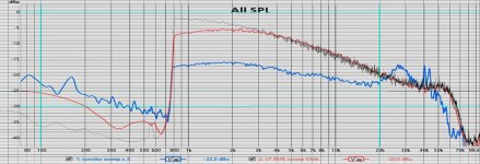
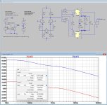
When I project the Frequency response from this .wav file on the one you just showed us, I get different results, see image below.
Yours is the red line and mine is the black line.
From 4K and upwards, both are the same, but below 4K they start to deviate and at 1KHz difference is already 5dB.
So maybe this explains the differences in relative gain between the two different Cart recordings at LF.
After all your Sumiko responds quite a bit better to the sweep from 2KHz to 20KHz , but above 20Khz this Cart is resonating quite significantly.
Hans
Something is partly wrong with your images.
I still have the .WAV file that you sent me from the Ortofon sweep with your Benz.
When I project the Frequency response from this .wav file on the one you just showed us, I get different results, see image below.
Yours is the red line and mine is the black line.
From 4K and upwards, both are the same, but below 4K they start to deviate and at 1KHz difference is already 5dB.
So maybe this explains the differences in relative gain between the two different Cart recordings at LF.
After all your Sumiko responds quite a bit better to the sweep from 2KHz to 20KHz , but above 20Khz this Cart is resonating quite significantly.
Hans
Attachments
Thanks for looking at it!
I opened 4 sweeps recorded earlier with 2 different preamps, but all with Benz, they are very similar in shape. So i have no explanation why you got flater line between 800Hz and 3 kHZ from waw.
On the bottom is sweep with RIAA filter, just as reference.

The gain below 800Hz is because yesterday I made several repeated sweeps with lifting and lowering cartridge several times. Under 800HZ high level is just because that bump when cart is lowered at LP. Sorry I did not paid attention as that was region of no interest. ,
Now I quickly run 2 sweeps separate with Sumiko without repeating, start and stop recording while the cart is on LP, now is as we like to see it.
Here is 2 new peaks of Sumiko (with more quiet LF) and one I posted yesterday for ref.

I opened 4 sweeps recorded earlier with 2 different preamps, but all with Benz, they are very similar in shape. So i have no explanation why you got flater line between 800Hz and 3 kHZ from waw.
On the bottom is sweep with RIAA filter, just as reference.
The gain below 800Hz is because yesterday I made several repeated sweeps with lifting and lowering cartridge several times. Under 800HZ high level is just because that bump when cart is lowered at LP. Sorry I did not paid attention as that was region of no interest. ,
Now I quickly run 2 sweeps separate with Sumiko without repeating, start and stop recording while the cart is on LP, now is as we like to see it.
Here is 2 new peaks of Sumiko (with more quiet LF) and one I posted yesterday for ref.
As an aside, I also have the high output Sumiko Blue Point with the upper registers being very good sonically. I suspect the physical weight of the cartridge and the light moving mass of the arm I was using, left it lacking in the low registers sonically.When drawing the 10dB/dec line for both Carts from 2Khz to 20Khz, you see that the Sumiko isn't that bad with only +/-1dB deviation on average, where the Benz deviates 5dB at 20Khz
The network illustrated below was intended in part to have a high PSRR to allow for higher noise supplies. However to achieve that outcome requires reasonably tight tolerances to be most effective. In using LTSpice (now running in me as a virus catching up to Grandma) the results addresses some of the implications.I used the LM4562 because the PSRR is very high - it is 100dB or better at LF and even at 100kHz, it is still very high - and you get low noise as well. The MC front end on my design has essentially 0 dB PSRR - so it has to be married up to a very clean power supply. I have not used shunt regs, but my only concern for a simple 1 transistor shunt reg would be the regulator noise and then the available loop gain to shunt any power supply noise/ripple. Again, I do not have practical experience with these regs, so this is only my opinion.


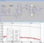
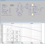
In the first screenshot AC signals were applied to the V+ supply (that includes the NE5532 as well, but not the AD844 to reflect what is planned) whereupon resistors R8,R9,R10 and R12 are all 3 kOhm in value. Although it is clear that such absolute symmetry in all things cannot possibly exist in reality, the PSRR is extreme at an incredible -160dB from 10Hz to 100kHz. However with just a 0.1% change in the resistance value of R12, the PSRR drops to about 80dB in the middle screenshot. In the third screenshot AC signals were alternatively applied to the V- supply whereupon R9 was modified by 0.1% to 3.003 kOhms, resulting in PSRR starting at -24dB and lookingly strangely like an RIAA curve. Don't know about this one... though it does form a voltage divider across the MC.
Last edited:
I think that’s a good figure. Clearly it’s not good to operate the MC with that kind of DC current flowing in the coil, but under a fault condition, I don’t think the cart would be damaged at all.Thank you Bonsai,
I see what you mean, worst case of complete transistor failure is still Vps / 1k047 of resistance.
In Hierfi's design , following same logic is even less, if both transistors fail one open, other shorted (quite low statistics for that) : max current wold be 12 V (+-6V PS) / 6k (3k in emitter and 3 k in collector) = 2mA.
So I believe that consensus is that normal MC cart can take up to 5mA DC through the coil without damage?
Kind regards,
Dražen
Agree - a lot of folks have had problems with them so you have to be very careful.You have to be real careful in handling the LM4562 (post 613). They seem to be anomalously sensitive to static damage. The net effect is something that sounds like popcorn noise. I ended up with tubes of the darned things in this mode. Since I have an antistatic mat on the bench, if I come close to using them again, I'm going to handle them on that.
I ended up replacing them with NE5532's, which seems to be a lot more robust. And the maximum rail is +/- 22V, giving a useful headroom boost over the LM4562's +/- 18V. The 5532 has a lower slew rate, and is slightly noisier, but an ancient and reliable workhorse.
There was rumours that TI were obsoleting the 5532 and 5534. They indeed were not available for a while (and led to panic buying), but that was due to TI changing over fab facilities. They are both now available in quantity again.
You can tell I'm a real fan of these Paleolithic devices. Indeed for MM cartridges, it is very difficult to better the 5534A for noise. The much more recent OPA210 is better - critically the same current noise as the 5534, but around half the voltage noise. The 1/f noise is much lower in frequency, and that might be important given the RIAA boost at low frequency. Not counting 1/f, the OPA210 finds you a reduction of 0.6dB of noise, and is 3.6 times more expensive.
Craig
When having +/-15Volt available, you could change the negative supply voltage on the LTP amp from -6V to -15V and change R8 and R9 accordingly to ca 8K to keep the current at 1.8mA.In the third screenshot AC signals were alternatively applied to the V- supply whereupon R9 was modified by 0.1% to 3.003 kOhms, resulting in PSRR starting at -24dB
This will improve the negative PSRR.
When you also use a pot instead of R9 to tune the output offset to zero volt DC, the negative PSSR can be reduced thereby also compensating to some degree for tolerances in R10 and R12.
When placing a 2k5 resistor on top of R10 and R12 and connecting this resistor on the other side to +15Volt, you can completely discard the +/-6Volt.
But in the end you will need a clean supply which is not really a problem with modern LDO's producing voltage noise in the low nV/rtHz.
Hans.
Don't think I did it correctly Hans. I removed all the RIAA components and just used 2 -10kOhm loads around ground and used a 20kOhm Rg, meaning that there is unity gain between input and output. I then injected 1 volt signals into the power supplies and looked at the output. This means that the power supply rejection is directly related to the normal unity gain transfer. Does this make sense? Perhaps I am looking more at CMRR? It seems PSRR and CMRR should correlate to some degree in this network. The results are as follows:


Last edited:
I should have mentioned that the image on the left is for 1 volt modulation of the -ve power supply and the right for 1 volt modulation of the +ve supply. As observable from the schematic the value of R12 has been altered to 3.003k (0.1%) in both.
Last edited:
For comparitive purposes the results are below for greater error in R12, being changed to 3.03k (1%) from 3.003k (0.1%)


IMO when testing an amp, it should be done in it´s complete setting, including Riaa.
Since I think it makes sense to use just one set of supplies, either +/-6V or +/-15Volt, let's consider both options.
1) +/-6Volt supply.
With the given circuit diagram, weighted Equivalent Input Noise was in the order of 61nV or 0.24mV at the output with the used gain of 72dB.
To get the same noise from the power supply when the PSRR from the negative supply is around 40dB@1Khz, this would mean 0.24mV/40dB = 2.4mV
This is a ridiculous high figure when using modern LDO that produce noise in the low nV/rtHz, so at least a factor 100 lower.
Also when fed with batteries this would fully stay way below the amp's own noise.
So IMO, there is absolutely no reason for concern when either fed with batteries or with a modern LDO.
2) +/- 15Volt supply.
In case the result of made by LDO's, the same as above applies.
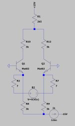
When less sophisticated supply is used, a simple remedy is to place a current source in the negative part of the LTP, see attachment.
This will improve PSRR by a very great amount.
In both supply cases, CMRR will be very good.
Hans
Since I think it makes sense to use just one set of supplies, either +/-6V or +/-15Volt, let's consider both options.
1) +/-6Volt supply.
With the given circuit diagram, weighted Equivalent Input Noise was in the order of 61nV or 0.24mV at the output with the used gain of 72dB.
To get the same noise from the power supply when the PSRR from the negative supply is around 40dB@1Khz, this would mean 0.24mV/40dB = 2.4mV
This is a ridiculous high figure when using modern LDO that produce noise in the low nV/rtHz, so at least a factor 100 lower.
Also when fed with batteries this would fully stay way below the amp's own noise.
So IMO, there is absolutely no reason for concern when either fed with batteries or with a modern LDO.
2) +/- 15Volt supply.
In case the result of made by LDO's, the same as above applies.
When less sophisticated supply is used, a simple remedy is to place a current source in the negative part of the LTP, see attachment.
This will improve PSRR by a very great amount.
In both supply cases, CMRR will be very good.
Hans
Attachments
Last edited:
I thought that noise was not that much a factor, though had no idea of the extent. You are still way ahead of me, particularly in my understanding of "weighted Equivalent Input Noise". Noise in general that I haven't begun to think about much (hopefully you can give me a hand with it in LTSpice if I run into trouble).IMO when testing an amp, it should be done in it´s complete setting, including Riaa.
Since I think it makes sense to use just one set of supplies, either +/-6V or +/-15Volt, let's consider both options.
1) +/-6Volt supply.
With the given circuit diagram, weighted Equivalent Input Noise was in the order of 61nV or 0.24mV at the output with the used gain of 72dB.
To get the same noise from the power supply when the PSRR from the negative supply is around 40dB@1Khz, this would mean 0.24mV/40dB = 2.4mV
This is a ridiculous high figure when using modern LDO that produce noise in the low nV/rtHz, so at least a factor 100 lower.
Also when fed with batteries this would fully stay way below the amp's own noise.
So IMO, there is absolutely no reason for concern when either fed with batteries or with a modern LDO.
2) +/- 15Volt supply.
In case the result of made by LDO's, the same as above applies.
When less sophisticated supply is used, a simple remedy is to place a current source in the negative part of the LTP, see attachment.
This will improve PSRR by a very great amount.
In both supply cases, CMRR will be very good.
Hans
As it seems I can't get away from LTSpice now (many thanks to you Hans... having spent many more furlong lengths of my not so precious time on it since yesterday), things seem mostly clear as to why the difference between the rejection in the positive and negative supplies. This was helped by simplifying the network, removing the RIAA network and connected it unity gain, becoming mostly obvious in doing so.
This is particularly revealing by the testing of CMRR specific to the negative supply alone, with the two tests specific to that shown again below:


What was first noticed was that the base line rejection was 40dB for a 1% change in R12, but 60dB for a 0.1% change. In further testing (instead of mowing the lawn now in the dark... though economizing on the cost of diapers) the decimal point was moved along with increasing 20dB steps to 3.000003 kOhm, resulting in noise limiting at -180dB. The mechanism is that variant voltage signals on the negative supply cause equal variant currents in the lower values of equal value resistances (both 3kOhm)that have their opposing end connected to low impedance emitters of the input pair. These equal currents are reflecting in their collectors but have different output gain caused by the difference in their load resistances. Hence there becomes this direct correlation.
With positive variance in the supplies the opposing ends of the resistors are connected to the high impedance collectors, hence no variance voltage occurs across the load resistors as currents remain unchanged, even though they have variant resistance. As can be seen if going back to previous posts, the rejection deteriorates as frequency goes up, suggesting that capacitances are causing differences seemingly becoming a load that causes differences in those load resistances.
Last edited:
The post above also indicates the reason why a constant current source has clear advantage in the negative supply, as Hans has concluded. The problem relates predominantly (perhaps only) with simplicity and diminished convenience, meaning I hope I don't have to do it.
Constant current sources cause constant voltage drops across the load resistors in the collectors of the LTP, whereupon the collector voltage on the LTP is then dependent upon three factors, the value of the constant current, the value of the load resistors, and the value of the positive supply. In the case of using four identical resistors the collector voltages become set to about + 0.6 volts mostly independent of the value of resistors used, meaning that quiescent current can be reduced or increased, being changing by a set of 8 (perhaps 0.1%) resistors for stereo being perhaps economized being purchased in 10's, and the collector voltage remains about 0.6 volts without much thinking... besides my brain already hurts... where's my mommy?... mommy!...mommy!... make it stop...
Constant current sources cause constant voltage drops across the load resistors in the collectors of the LTP, whereupon the collector voltage on the LTP is then dependent upon three factors, the value of the constant current, the value of the load resistors, and the value of the positive supply. In the case of using four identical resistors the collector voltages become set to about + 0.6 volts mostly independent of the value of resistors used, meaning that quiescent current can be reduced or increased, being changing by a set of 8 (perhaps 0.1%) resistors for stereo being perhaps economized being purchased in 10's, and the collector voltage remains about 0.6 volts without much thinking... besides my brain already hurts... where's my mommy?... mommy!...mommy!... make it stop...
Just having a bit more time as this morning, I went into the matter of CMRR.
1) See first Attachement how this looks with perfect resistors in the LTP.
The blue line is the output signal when ca. 1V input is given in Diff mode and the red line is the CM output with the same input signal.
CMRR is now the difference between +73dB@1Khz in Diff mode and below -120dB in CM, or >190dB.
2) Now give one collector resistance a 0.1% deviation to 3k003 and CMRR drops to 69.5dB, still a very respectable figure,
When keeping the collector resistances at 3K, but changing one emittter resistor to 3.003K gave practically the same result.
But look at the output voltage, it's 1.76Volt DC, quite unacceptable.
3) When tuning one emitter resistance to 3K0094 bringing down DC at the output, made hardly any difference in CMRR, but it shows that it makes sense to place a pot in one of the emitter legs.
In the first attachment you see how the CM connection was made and in the two following images you see the Diff mode connection.
All three simulation had both circuit diagrams together in one model, but only one at the time is shown here not to make the image too crowded and unreadable.
Hans
Attachments
DC shifting was also found in the physical reality for many reasons, including variances in the input transistor pair also causing variances thermally related. This is one of the reasons for trying to hold the collector voltages at a lower value. Lower voltages just create less heating with lower thermal consequences, though perhaps with negative consequences electronically in doing so. Don't know of any optimum yet.
I am trying to avoid DC servo's in the low level signal side, simply to reduce the possibility of interference there. The solution seems about as simple as it can get (as per below), as long as the input stage doesn't go "out of whack" to the extent the servo's can't adjust. Thus far I haven't noticed corrective voltages on the output of the servo's beyond about 2 volts, hence still staying well within the +/- 15 volt power supply range. Of note is that my RIAA values are different than yours shown, that in your network the 10megOhm will be in parallel with yours at 141k4, changing the 50 Hz pole slightly.
There is another issue I am trying to address, though I don't necessarily need to. This involves the connection and disconnection of the moving coil from the network. Mainly the network shouldn't be "shocked" by it. The solution seems requires the addition of a secondary pot in the +ve supply in conjunction with what can be described as a convoluted adjustment procedure, though I haven't tested this.

p.s. - the capacitor above is intended 0.22uF
I am trying to avoid DC servo's in the low level signal side, simply to reduce the possibility of interference there. The solution seems about as simple as it can get (as per below), as long as the input stage doesn't go "out of whack" to the extent the servo's can't adjust. Thus far I haven't noticed corrective voltages on the output of the servo's beyond about 2 volts, hence still staying well within the +/- 15 volt power supply range. Of note is that my RIAA values are different than yours shown, that in your network the 10megOhm will be in parallel with yours at 141k4, changing the 50 Hz pole slightly.
There is another issue I am trying to address, though I don't necessarily need to. This involves the connection and disconnection of the moving coil from the network. Mainly the network shouldn't be "shocked" by it. The solution seems requires the addition of a secondary pot in the +ve supply in conjunction with what can be described as a convoluted adjustment procedure, though I haven't tested this.
p.s. - the capacitor above is intended 0.22uF
This can elegantly be solved with two servo's, making the emitters to be at exactly zero volt.There is another issue I am trying to address, though I don't necessarily need to. This involves the connection and disconnection of the moving coil from the network. Mainly the network shouldn't be "shocked" by it.
This solves two problems:
1) connecting and disconnecting the Cart giving a loud plop in the speakers
2) when accidently one of the cart signals touches ground, nothing happens.
And to a certain degree it helps to adress the output offset, but your solution with a pot at the +6V side helps to correct the output offset even further.
Personally I'm not so charmed about the two servos in the Riaa network because they will have un undefined impact on the Riaa correction
Hans
Attachments

Again me with uneducated question; isn't referencing bases to virtual ground (eg opamp U9 and U10) output going top feed them opamp output noise?This can elegantly be solved with two servo's, making the emitters to be at exactly zero volt.
Besides, who changes carts with preamp on?
You've got me, a very bad idea.Again me with uneducated question; isn't referencing bases to virtual ground (eg opamp U9 and U10) output going top feed them opamp output noise?
Hans
- Home
- Source & Line
- Analogue Source
- Fully balanced MC phono preamplifier thoughts