I notice THD increase with simple circuits I was playing with in early stage of this thread, but you are right of course, these were just 2 examples and not very elaborated.That Trans impedance increases THD is completely dependent on the circuit you use, there is no other reason why THD should increase, but yes the setting has to be changed for every other Cart.
In a well designed circuit, as there are several, risk of frying your Cart can be prohibited at switch on and off, but this is a serious item to consider in the design.
To set dedicated preamp (or at least front end) for each chart is however good option I think, considering huge cost of good MC and modest cost of preamp, each expensive cart should get optimal preamp to get most of it out, this is me economist speaking 🙂
Hi Bonsai, do you have proposal for this protection circuit?It’s very easy to arrange to limit the current to the front end stage so that in the event one of the devices pops and goes short to the supply rail, the current is no more than 4 or 5 mA.
J
Hans
In my head amp I can choose from four gain positions, with jumpers on pin headers. That will do for every possible Cart.To set dedicated preamp (or at least front end) for each chart is however good option I think, considering huge cost of good MC and modest cost of preamp, each expensive cart should get optimal preamp to get most of it out, this is me economist speaking 🙂
Hans
Attachments

My skills in LTSpice are advancing thanks to Hans... though I'm still a furlong slower than the speed of my pet snail that I gave the name Grandma. My grandmother was a formidable woman... though somewhat senile in advancing age... "furlong slower" means the time it took for her in her declining years to plow that distance across an imaginary field being chased by an imaginary ox... In retrospect I still feel somewhat guilty in not tying up the ox...may she rest it peace...
I finally managed to obtain a simulation with crossed clumsy fingers as per below. In this, I altered some values to set the output to 1 Volt RMS, though I see now that the output is across the differentials, hence only 1/2 Volt per side. I also changed the output connection in advance of the buffered output to exclude the output buffers. I expect the measurement device has infinite impedance though don't know for sure. As is revealed the distortion reduction by the addition of U3 and U4 is formidable in addressing Ro nonlinearities of the inverting input terminals when driven with extreme variance created by the exclusion of feedback.

I finally managed to obtain a simulation with crossed clumsy fingers as per below. In this, I altered some values to set the output to 1 Volt RMS, though I see now that the output is across the differentials, hence only 1/2 Volt per side. I also changed the output connection in advance of the buffered output to exclude the output buffers. I expect the measurement device has infinite impedance though don't know for sure. As is revealed the distortion reduction by the addition of U3 and U4 is formidable in addressing Ro nonlinearities of the inverting input terminals when driven with extreme variance created by the exclusion of feedback.
Yes it has infinite impedance.I expect the measurement device has infinite impedance though don't know for sure.
Since the 0.0006% distortion is identical to a setting with 2.5Vrms out including the AD844's output buffers, it's obvious that all THD is caused by the LTP.
Hans
Hi Bonsai, do you have proposal for this protection circuit?
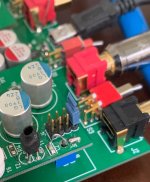
Here is the simplified front end of the X-Altra MC/MM - the current through the cart with Q2 shorted is about 4mA and about 2.5mA with the servo (U1) engaged. I disconnected it here to show worst case. V2 and V3 is an 1/2 LM4562 opamp each. You could belt and brace this by placing a 5.6V zener from each 5V rail after the 470 Ohm resistors to 0V. The other alternative in this example would be to raise the regulator output voltage to say 8 or 9 volts, and then raise the value of the 470 ohm resistors to give the desired voltage at C5 and C6. This would provide good clamping and short circuit current limiting with the zeners. Although I did not do it in my preamp, its good practice to place a pair of anti-parallel diodes across the MC input (1N4007 or similar). These will never conduct in normal circumstances, but they will clamp any high voltages accidently getting onto the input from an external source.
Still a host of other considerations Drbulji...Bravo Hierfi!
Hi Bonsai,
I'm a bit confused by V4 and V5.
You power supply is 30Volt and the MC amp is fed with 10Volt, a difference of 20Volt.
So shouldn't V4 and V5 not be resistors to bridge the 10V difference between 15Volt and 5Volt ?
Hans
I'm a bit confused by V4 and V5.
You power supply is 30Volt and the MC amp is fed with 10Volt, a difference of 20Volt.
So shouldn't V4 and V5 not be resistors to bridge the 10V difference between 15Volt and 5Volt ?
Hans
That was just a quick and dirty sim from a few yrs ago when I was working on it that I posted up. The reference voltage for the front-end regulator is via resistive dividers from the +-15V rails which are heavily decoupled by 220uF caps. I just drew this representation up now to make it clearer. The PSU simmed noise is 50 pV/rt Hz.

As an aside, how does your regulator compare to a basic shunt network like the one below Bonsai? This is the network I am currently using as copied somewhere from the diyAudio site, being also mirrored for the negative side? These were so simple I used independent regulators for each channel. Being of nature shunt this limits the available current in the event of faults... though not necessarily enough yet to prevent damage to the coils.

Shunt regs have only two ports so no need for a mirrored version (in terms of transistor type). Just connect the current feed resistor to the other side.being also mirrored for the negative side?
I used the LM4562 because the PSRR is very high - it is 100dB or better at LF and even at 100kHz, it is still very high - and you get low noise as well. The MC front end on my design has essentially 0 dB PSRR - so it has to be married up to a very clean power supply. I have not used shunt regs, but my only concern for a simple 1 transistor shunt reg would be the regulator noise and then the available loop gain to shunt any power supply noise/ripple. Again, I do not have practical experience with these regs, so this is only my opinion. As I noted earlier, the worst case fault current through the MC coil is 4mA. you would notice it straight away since the preamp would not work if this happened, so it's not a 'lurking' fault.As an aside, how does your regulator compare to a basic shunt network like the one below Bonsai? This is the network I am currently using as copied somewhere from the diyAudio site, being also mirrored for the negative side? These were so simple I used independent regulators for each channel. Being of nature shunt this limits the available current in the event of faults... though not necessarily enough yet to prevent damage to the coils.
View attachment 1375155
Thank you Bonsai,As I noted earlier, the worst case fault current through the MC coil is 4mA. you would notice it straight away since the preamp would not work if this happened, so it's not a 'lurking' fault.
I see what you mean, worst case of complete transistor failure is still Vps / 1k047 of resistance.
In Hierfi's design , following same logic is even less, if both transistors fail one open, other shorted (quite low statistics for that) : max current wold be 12 V (+-6V PS) / 6k (3k in emitter and 3 k in collector) = 2mA.
So I believe that consensus is that normal MC cart can take up to 5mA DC through the coil without damage?
Kind regards,
Dražen
One interesting off subject observation, without wish to change subject from preamp.
Since I have indications that my Ruby 2 cart is worn, I installed Sumiko Blue Point that I have laying for years, that one has very little running hours. I know it is hi output MC, more like MM, but needed to check.
From first it is obvious that BM Ruby is several classes better cart (no wonder when I tried it first Sumiko went to bin). Without showing pictures now; channel separation is horrible, distortion visible even on scope...). Nevertheless it does work
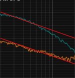
Back to main question, here I compared Ortofon LP sweeps (these are peeks captured after 3-4 runs of needle over the track). Both are recorded without RIAA by RME mic amp (on different gain settings)
Hans earlier explained that sweep should have 10db drop / decade after 2kHz. I tried to make line between 20khz and 2khz and
Sumiko (bottom trace) has about 5db drop
Ruby has about 14db drop (and by far cleaner trace 🙂)

I applied little smoothing to traces so they are easier to look at.
Does this have explanation, both carts are bad?
Thank you!
Since I have indications that my Ruby 2 cart is worn, I installed Sumiko Blue Point that I have laying for years, that one has very little running hours. I know it is hi output MC, more like MM, but needed to check.
From first it is obvious that BM Ruby is several classes better cart (no wonder when I tried it first Sumiko went to bin). Without showing pictures now; channel separation is horrible, distortion visible even on scope...). Nevertheless it does work
Back to main question, here I compared Ortofon LP sweeps (these are peeks captured after 3-4 runs of needle over the track). Both are recorded without RIAA by RME mic amp (on different gain settings)
Hans earlier explained that sweep should have 10db drop / decade after 2kHz. I tried to make line between 20khz and 2khz and
Sumiko (bottom trace) has about 5db drop
Ruby has about 14db drop (and by far cleaner trace 🙂)
I applied little smoothing to traces so they are easier to look at.
Does this have explanation, both carts are bad?
Thank you!
Dražen,
Why is it that I see 1/48 at the bottom of your sweeps.
Doesn't this mean that you are still in the octave mode ?
If so, your images are meaningless for the purpose of interpreting the Ortofon sweep.
Hans
Why is it that I see 1/48 at the bottom of your sweeps.
Doesn't this mean that you are still in the octave mode ?
If so, your images are meaningless for the purpose of interpreting the Ortofon sweep.
Hans
No Hans, that is 1/48 smoothing, records are in spectrum mode. Here without smoothing so 1/48 doesn't confuse:

What still puzzles me about the Sumiko is why the output below 800Hz is higher as from the Benz, but above 800Hz lower as the Benz.
Could this be a relative gain factor that is not equal, and I don't mean absolute gain because that would only shift the complete image upwards in dB
Your Sumiko has a much higher output, so for constructing the image you must have done something ?
Hans
Could this be a relative gain factor that is not equal, and I don't mean absolute gain because that would only shift the complete image upwards in dB
Your Sumiko has a much higher output, so for constructing the image you must have done something ?
Hans
- Home
- Source & Line
- Analogue Source
- Fully balanced MC phono preamplifier thoughts