Hi guys,
wesayso, thx for the heads up that Erin put his test results up.
fluid, i think your sim makes sense because...
nc535, the 60x60 i have running right now is the narrowest H pattern I've tried, and one aspect about it that jumps out is how much more audibly defined the 60 degree H pattern's edge is than any of my wider H builds.
By edge, i mean in terms on VHF/HF rolloff.
Even barely inside the 60 degree wall angle is totally fine listening; even barely outside ....it's a different animal..
I'm guessing a narrower pattern makes for a sharper VHF roll-off.????
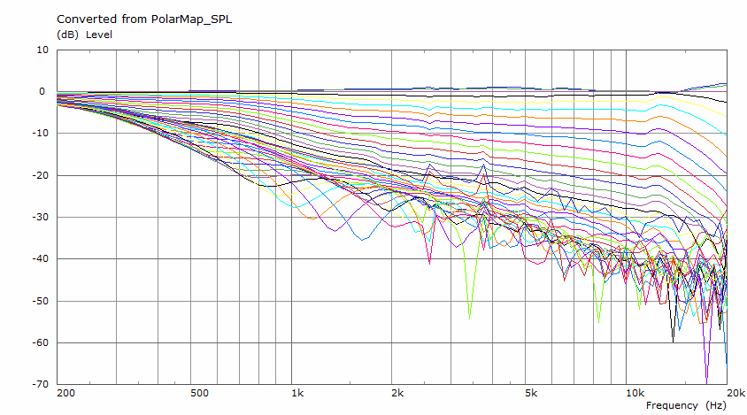
Here's 10 deg red, 20 deg blue, and 30 deg green out to the 60 H pattern edge. As you can see, VHF hangs in well. (there's a 20kHz low-pass in place)
The aqua is 40 deg.....

(This is the only tuning i've made for the box, a quickie indoors and at 1.5m...so traces shown are 1/3 octave smoothing awaiting cleanup outdoors)
wesayso, thx for the heads up that Erin put his test results up.
fluid, i think your sim makes sense because...
nc535, the 60x60 i have running right now is the narrowest H pattern I've tried, and one aspect about it that jumps out is how much more audibly defined the 60 degree H pattern's edge is than any of my wider H builds.
By edge, i mean in terms on VHF/HF rolloff.
Even barely inside the 60 degree wall angle is totally fine listening; even barely outside ....it's a different animal..
I'm guessing a narrower pattern makes for a sharper VHF roll-off.????
Here's 10 deg red, 20 deg blue, and 30 deg green out to the 60 H pattern edge. As you can see, VHF hangs in well. (there's a 20kHz low-pass in place)
The aqua is 40 deg.....
(This is the only tuning i've made for the box, a quickie indoors and at 1.5m...so traces shown are 1/3 octave smoothing awaiting cleanup outdoors)
how do you model the throat, the round to square transition?
Typical practice is to drill 1" round through square opening and fill in the corners with putty. Be interesting to see what difference various approaches and amounts of fill make
Typical practice is to drill 1" round through square opening and fill in the corners with putty. Be interesting to see what difference various approaches and amounts of fill make
I suspect that having headroom (and plenty of it) is one of the qualities that is hard to beat. So I agree that having one mid would not be a choice I would make.
The Hyperion is a domesticated version of a synergy, starting with a more sophisticated and better behaved horn. At least that's what I suspect.
Whatever you do, I'd recommend to build in as much headroom as you can (up to a point where it's still economical to do so). 🙂
If you do that, you'd be well on your way to come out quite close to (or surpass) these results.
Well, I've got lots of midwoofers - 16- but in some regions side woofers work against front woofers to create cardioid. Might have passed economical a while back.
From about 400 Hz up, the 8 front woofers work unopposed. From 100 Hz to 400 Hz, side woofers are delayed and inverted to cancel fronts at sides and to the back. Below 100 Hz, side woofers aid front woofers to extend down to about 60 Hz at 105db peak without boundary support.
That should be plenty of headroom, subwoofer assisted at the bottom.
how do you model the throat, the round to square transition?
Typical practice is to drill 1" round through square opening and fill in the corners with putty. Be interesting to see what difference various approaches and amounts of fill make
"What, me model?"
(Might as well be asking Alfred E Neuman to worry haha 😀)
But seriously, here's what i've tried....for a 1.4" CD.
a. Drilling a 1" round hole, and carving out horn walls to fit the 1.4" CD.
b. Drilling a 1.4" round hole, and filling in the corners with putty.
c. Drilling a 1.4" round hole, and not bothering with filling in the corners
d. Drilling a 1.2" round hole, carving out a little, and filling in a little.
I just drilled a 1.2" round hole for first time on the syn9 60x60.
I carved the horn walls; but have yet to putty the corners....which will take substantially less effort to putty, than the 1.4" hole route.
It looks so far, like the easiest way to go. Wish i had thought of it long ago.
In terms of how the different techniques have measured.....
Well, i know this is heresy, but i haven't found enough difference to really care about. That includes c. do nothing !
I do the transition work anyway...just out of OCD paranoia i guess !!
my question was re' fluid's sim but by the time I posted it, that context was lost.
lot easier to tell if it makes a difference in simulation than manual measurement of polars
lot easier to tell if it makes a difference in simulation than manual measurement of polars
In my sim there was is no transition between round to square. The driver fires into a square throat like the SH50.

I doubt it hurts to smooth the transition but there is already a discontinuity between the conical exit of the driver and the entry of the waveguide. If the CD has attempted to create a flat wavefront that is also not a good match for a straight conical horn.
I suspect it is hard to see a difference when mixed in between those other issues.
Attachments
mabat was kind enough to publish the .cfg file so I found it interesting to simulate it. Doing the sim 300 hz to 18 khz with 64 freqs took 2.5 hrs. I then realized it had only computed 90 degree directivity. That was enough for a comparison.
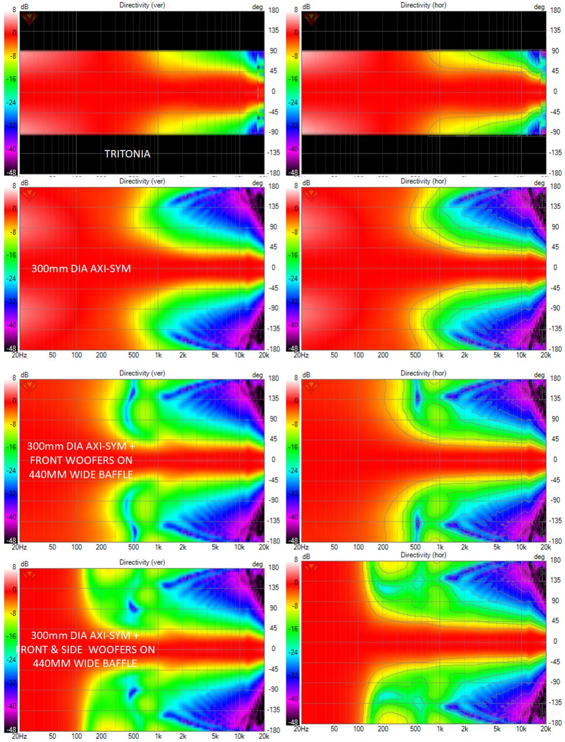
The top row is Tritonia stand alone. It provides constant, controlled directivity down to about 1 khz and is impressively smooth. Overall dimensions are 422mm x 364mm.
The next row is my 300 mm dia axisymmetric waveguide. Its quite a bit smaller and has a narrower beam (60 vs 80 degrees) but it controls directivity down almost as far and then widens very gradually.
Augmented with front woofers that fit on a 440 mm wide baffle (next row down) it gives control to more than an octave below Tritonia.
Finally, adding side woofers for cardioid extends control downwards another 2 octaves.
Admittedly my simulations don't yet address the effect of the nearby waveguide rollback with the front woofers but if that proves to be small, then its quite clear which is a better path to wideband controlled directivity.
Attachments
An infinite baffle sim can only give you +/- 90.I then realized it had only computed 90 degree directivity.
Admittedly my simulations don't yet address the effect of the nearby waveguide rollback with the front woofers but if that proves to be small, then its quite clear which is a better path to wideband controlled directivity.
This sim says don't do it. Have a look at the ST260B scaling that up and rounding the edges of the baffle should give a pretty good response. A narrower version could be made to match the existing one if that is the pattern you want.
I did one of those myself a while back and got better results. Likely easier repeating it than finding it at this point. Hopefully, its different for a 60 deg waveguide...
I suspect the box behind needs to be about same size or smaller than the WG in order to get rid of the diffraction problems in the listening window. The problem is the physical dimensions are different for the two systems (WG and the box behind) but around xo they both have output at same wavelengths. Both "systems" could have smaller physical dimensions to not diffract wavelengths at xo frequency but this is hard to pull of. ATH sims show the freestanding guide with rollback affects directivity little below physical dimensions suggest so it might be possible but you have to minimize size of the box behind. Get them systems to be the same size and you might be pull this off without problems = mount the woofers somewhere of the waveguide profile but no further. At the rim or as in multiple entry horn. If this is not possible, you might have to accept a little bit of diffraction 🙂 ST260B on large baffle with the woofers around and generous roundovers might be the other option. Both have some diffraction, it is very hard if not impossible to eliminate with finite baffle. You might try to move the diffraction somewhere on the low mids with large baffle as well. Maybe it is not so audible.
Maybe diffraction is not problem at all. Many seem to be happy with the multiple entry horns despite all of them seem to have diffraction / mouth reflection "problems".
Maybe diffraction is not problem at all. Many seem to be happy with the multiple entry horns despite all of them seem to have diffraction / mouth reflection "problems".
Last edited:
I imagine it could be improved by greater distance to the edge and more rounding, a narrower pattern would also keep more off the edge.
The point of a freestanding guide is to allow the curve to flow from throat to mouth edge and behind with no abrupt change in curvature. If there is going to be a baffle it makes much more sense to bring the waveguide to the baffle and round it right at the edge. That is the best in baffle result I have. Widening the baffle to accommodate the other drivers is worse but not significantly so.
A full 3D sim with a baffle mounted freestanding guide would be hard to do as the interface is tricky to get right making the result unreliable.
Last edited:
Both have some diffraction, it is very hard if not impossible to eliminate with finite baffle. You might try to move the diffraction somewhere on the low mids with large baffle as well. Maybe it is not so audible.
There is basically no diffractive ripple in a good guide rounded straight at the edge. The wobble remaining is sim mesh related. There is a change from the finite dimensions which extends the directivity lower. Audibility is a whole other question.
^^Is there any help of narrow pattern since it widens as frequency gets lower and at the xo the directivities should meet? If xo is high, where directivity is high on a narrow pattern waveguide, the woofers need to be closer each other to match that. If xo is low, the woofer spacing around the WG can be relaxed. Only about same physical size for the woofer arrangement and waveguide allows the directivities to meet? The woofer arrangement (think one big transducer, size of the woofer arrangement) could be smaller, but no larger than the WG, regardles of the directivity index at xo, if you want smooth transition?
^ yeah that would work, small woofers on the sides or make the baffle bigger to include the woofers at front and beyond that generous roundover, might work. But still there would be some diffraction due to the woofers disrupting the nice smooth waveguide, that now includes the box. It is hard to fit the woofers anywhere near (enough) the waveguide without introducing diffraction is my message. A little of diffraction somewhere or some mismatch in the directivity at xo seems to be the compromise. Diffraction interference doesn't seem to affect too much on the power response so might be better to go with little bit of diffraction and have smooth power response. Unless the diffraction is on the listening axis.. 😀 this is a brain twister
^ yeah that would work, small woofers on the sides or make the baffle bigger to include the woofers at front and beyond that generous roundover, might work. But still there would be some diffraction due to the woofers disrupting the nice smooth waveguide, that now includes the box. It is hard to fit the woofers anywhere near (enough) the waveguide without introducing diffraction is my message. A little of diffraction somewhere or some mismatch in the directivity at xo seems to be the compromise. Diffraction interference doesn't seem to affect too much on the power response so might be better to go with little bit of diffraction and have smooth power response. Unless the diffraction is on the listening axis.. 😀 this is a brain twister
Last edited:
I'll accept that I must have fooled myself or not looked closely enough when I ABECed rolled back waveguide on a baffle. Its been on my bucket list to try non-rolled back waveguide flush to the baffle.
Initially, my front woofers were bandpass but I was advised bandpass response was highly sensitive to individual driver characteristics - so I changed to direct radiator model. I may have to revisit that as I address baffle and diffraction issues.
I appreciate this morning's (to me) responses.
Initially, my front woofers were bandpass but I was advised bandpass response was highly sensitive to individual driver characteristics - so I changed to direct radiator model. I may have to revisit that as I address baffle and diffraction issues.
I appreciate this morning's (to me) responses.
There is clearly an optimum spacing and related XO. Vituix is a great help in finding it. I think I have smooth transition...^^Is there any help of narrow pattern since it widens as frequency gets lower and at the xo the directivities should meet? If xo is high, where directivity is high on a narrow pattern waveguide, the woofers need to be closer each other to match that. If xo is low, the woofer spacing around the WG can be relaxed. Only same physical size for the woofer arrangent and waveguide allows the directivities to meet? The woofer arrangement (think one big transducer, size of the woofer arrangement) could be smaller, but no larger than the WG, regardles of the directivity index at xo, if you want smooth transition?
The woofers being outside the waveguide have to be larger but that larger-ness is what allows them to extend pattern control. They can't be too much larger or CTC issues. Part of directivity match is dialing in right amount of overlap between woofers and CD/waveguide.
Putting small bandpass woofer ports right in the rollback allows higher XO but introduces complications from woofer sound going down into waveguide.
Yeah band pass holes seem nice, they bring the transducer physical feature down in size sacrificing the high frequency response, which is not needed anyway. A waveguide does the opposite, brings small transducer to big physical size. Introduce the two features on the same system and you have some bandwidth overlap to get the transducers physically close enough for smooth transition. Still there would be some diffraction on the band pass holes (for the waveguide emitted audio), unless some modern "metamaterial" trickery is used on the band pass holes making them invisible for the acoustics of the waveguide. Another possibility could be to make the waveguide beam high frequencies so that the band pass holes are outside of the frequencies they could diffract but close enough at the xo. Don't know if this is possible or would sound any good. The more there is data a MEH seems the most obvious solution. But to get the high directivity down in frequency the device must be pretty large... no win. Solve how to make diffraction free band pass hole and you have a system without diffraction 🙂
You have been working with the system a lot so I trust your judgement and I think you are capable to find very good compromise in the end 🙂 Fluid as well, a lot of work in to it. Thanks for sharing it, both of you!
ps. fluid my edit time is over on the previous post so I clear this up here: I was thinking and writing about waveguide system with surrounding woofers extending the pattern control down. A waveguide without woofers around performs nicely on a baffle or as freestanding as your simulation shows, without diffraction problems. Sorry my poor output quality 🙂
Last edited:
Thinking a bit more about it the woofers behind/around the waveguide could work just fine if you make the system big enough, assuming possible diffraction is low enough in frequency that it doesn't matter. What frequency is this I don't know but it sets the minimum size of such system and it might be too big for your plan and be too demanding for the compression driver. 1.4" driver might get the diffraction low enough, not sure about 1" driver would do it, maybe. Unable to find capable compression driver and a system with the woofers somewhere inside the waveguide would make more sense.
Last edited:
I did one of those myself a while back and got better results. Likely easier repeating it than finding it at this point. Hopefully, its different for a 60 deg waveguide...
Did you use a square shape? A round shape would introduce same distance at every angle from the source (worst shape). A square shape behind the waveguide softens the same effect.
(Yes I know the circular shape is way more convenient in fast simming 😉)
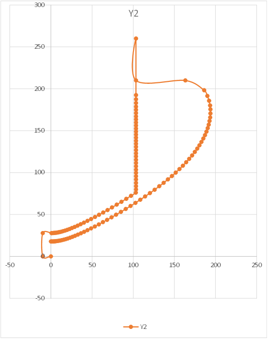
Heavens no; that would be too much work. I just modified the nodes.txt file which defines the profile of the axisymmetric horn to model a cylindrical back.
Here is the original profile and how I modified it
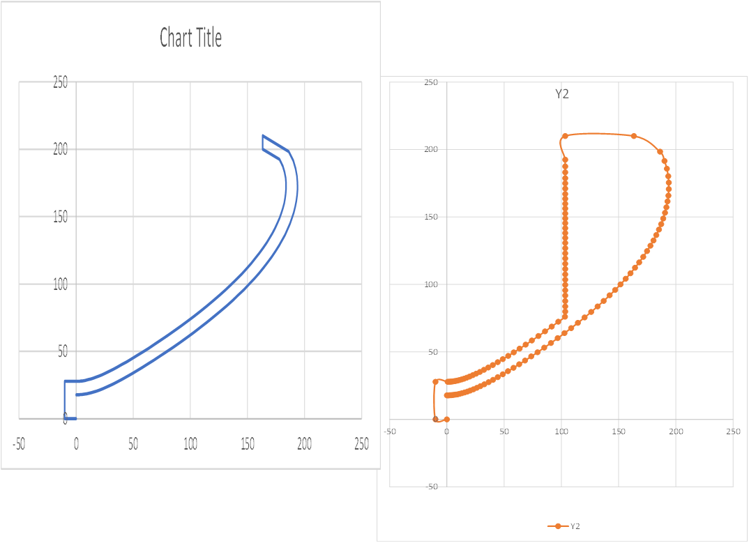
Here is the resulting response for this 420 mm waveguide:
It looks like I also intended to simulate this
including a baffle at the other end of the cylinder
but I don't see those results.
Since these appear to good to be true, I will take another look..
Here is the original profile and how I modified it
Here is the resulting response for this 420 mm waveguide:
It looks like I also intended to simulate this
including a baffle at the other end of the cylinder
but I don't see those results.
Since these appear to good to be true, I will take another look..
Attachments


Once you put a baffle behind the waveguide (with round-over), there will be diffraction from that baffle. I think that's the point made by fluid.
If you integrate the waveguide in a baffle with round-overs on the baffle (instead of the waveguide) the results would be better than the waveguide with round-over on top of a baffle. (as shown by fluid)
If you integrate the waveguide in a baffle with round-overs on the baffle (instead of the waveguide) the results would be better than the waveguide with round-over on top of a baffle. (as shown by fluid)
- Home
- Loudspeakers
- Full Range
- Full range line array for wall or corner placement