a paraline would be nice for a standard line array as well because you could get very small gaps between segments, better approximation to continuous line source....
hopefully simulation will shed light on why most DIY implementations have been less than impressive
hopefully simulation will shed light on why most DIY implementations have been less than impressive
... Its good to know what it costs to get that directivity. The simplicity without the directivity calls the worth of that directivity into question, even for me.
...
Hi, got pretty good results with freestanding waveguide and a cardioid box below. Attached is simulation result out of measurements of the individual components although in living room conditions so not the most accurate. Still, very simple to build and measure. Took some time to prepare the but it is not too much work after all, the rest of the project is pretty straight forward. Posted more info on D&D inspired thread in the multiway forum.
Attachments
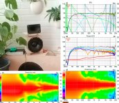
Hi, got pretty good results with freestanding waveguide and a cardioid box below. Attached is simulation result out of measurements of the individual components although in living room conditions so not the most accurate. Still, very simple to build and measure. Took some time to prepare the but it is not too much work after all, the rest of the project is pretty straight forward. Posted more info on D&D inspired thread in the multiway forum.
I guess its active cardioid that is expensive...unless time=$
I can't say I've resisted temptation to add cardioid but first try wasn't good..
Hi, got pretty good results with freestanding waveguide and a cardioid box below. Attached is simulation result out of measurements of the individual components although in living room conditions so not the most accurate. Still, very simple to build and measure. Took some time to prepare the but it is not too much work after all, the rest of the project is pretty straight forward. Posted more info on D&D inspired thread in the multiway forum.
Interesting data point seeing that top and bottom woofer (apertures) work through such small gaps. Your directivity is not as well defined as mine but then tuning a passive implementation is much harder, more tedious.
^They might not work through such small gaps 😀 the simulation is based on measurements of the individual components suspended on the measurement rig, not the whole speaker assembly so there probably is effect due to small gaps. Anyway, with smaller woofer (box) the bottom side could have wider gap or the woofer could be on the back. Same goes for the above, there is no need to have other obstacles there than the waveguide so I think it works just fine. You could use only side openings, just reduce the volume of the box to keep acoustic low pass about the same.
I'd say it is not too tedious, a bit scary though because obscure data or lack of data from the internets. It took only one evening to prep the prototype system and one day to measure all the variations, a weekend project. I've got detachable front and back panels and few different sized "walls" hacked together to be able to vary the volume inside as well as the aperture size fast. It looks like there is not too many variables (altough there probably are a lot more). I might have it too simplified, but it looks like from VituixCAD emulations and the prototype measurements that main thing you need to worry about is the back chamber volume and the opening area to tune the acoustic low pass 😀 I know there is more to it (like the actual dimensions what make the volume that will affect the performance) but I don't think there is anything to be afraid about. Minimal baffle yields minimal diffraction problems without roundovers so only thing to adjust is depth of the box and area of the openings. An active solution would also have to care about physical size.
I'd say it is not too tedious, a bit scary though because obscure data or lack of data from the internets. It took only one evening to prep the prototype system and one day to measure all the variations, a weekend project. I've got detachable front and back panels and few different sized "walls" hacked together to be able to vary the volume inside as well as the aperture size fast. It looks like there is not too many variables (altough there probably are a lot more). I might have it too simplified, but it looks like from VituixCAD emulations and the prototype measurements that main thing you need to worry about is the back chamber volume and the opening area to tune the acoustic low pass 😀 I know there is more to it (like the actual dimensions what make the volume that will affect the performance) but I don't think there is anything to be afraid about. Minimal baffle yields minimal diffraction problems without roundovers so only thing to adjust is depth of the box and area of the openings. An active solution would also have to care about physical size.
I agree passive isn't too bad if you like the development process. Dutch and Dutch succeeded eminently well and found it repeatable enough to support production. I on the other hand view a few extra drivers as a small price to pay for avoiding most of that work for a one-off effort and the arm-chair tunability.
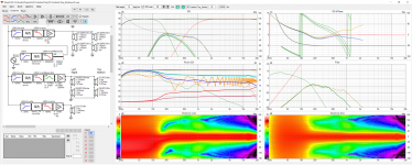
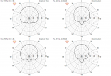
Before you posted the discouraging remark about whether or not bottom woofer can play through a slot, I came up with this concept, perching my prior 8 midwoofer cardioid top on a 15" bass bin:
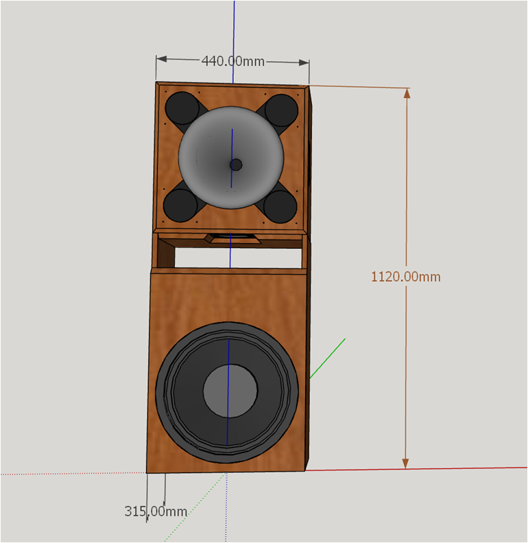
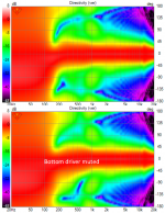
since the functionality of the bottom side woofer is in question, I did Vituix simulations with and without it. The lower graph below is with the bottom driver muted.

As you can see, the vertical pattern widens a little bit on the floor side between 200 and 500 Hz. One can live without that driver if the 100mm tall slot doesn't allow it to fill its role. Thus, its a non issue.
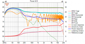
All told, I think this configuration may be the best bang for the buck. You extend the waveguide pattern to 500 Hz at the cost of 4 5" midwoofers, add benefits of cardioid between 200 and 500 Hz at the cost of 4 more 5" midwoofers, then add a 15" woofer that can be EQed flat to 20 Hz at reasonable listening levels.

(I'm still looking for a way to smooth that DI dip at 1 khz...)
Before you posted the discouraging remark about whether or not bottom woofer can play through a slot, I came up with this concept, perching my prior 8 midwoofer cardioid top on a 15" bass bin:
since the functionality of the bottom side woofer is in question, I did Vituix simulations with and without it. The lower graph below is with the bottom driver muted.
As you can see, the vertical pattern widens a little bit on the floor side between 200 and 500 Hz. One can live without that driver if the 100mm tall slot doesn't allow it to fill its role. Thus, its a non issue.
All told, I think this configuration may be the best bang for the buck. You extend the waveguide pattern to 500 Hz at the cost of 4 5" midwoofers, add benefits of cardioid between 200 and 500 Hz at the cost of 4 more 5" midwoofers, then add a 15" woofer that can be EQed flat to 20 Hz at reasonable listening levels.
(I'm still looking for a way to smooth that DI dip at 1 khz...)
Attachments

Freud I'd having a field day, all because these images have been stretched across my wide screen monitor.
Hehe, nice 😀
The bottom driver could be fine in the slot, you might need to measure it to be sure what to do with it. If it is there in the middle of the slot "ceiling" it shouldn't exite the lowest modes of the slot and the next ones are already close to 1khz aren't they? You seem to low pass the outer woofers from 500Hz.
The 1khz DI dip seems to be result of the crossover to rim woofers is where the waveguide loses the pattern control. I'm not sure how would you help with that other than getting the xo higher up or perhaps lower the DI below the dip transforming it a ramp up instead. I dont know what would be best compromise but this is the place where there is one, between the waveguide and rim woofers due to physical waveguide there on the way of the woofers.
I've never tried linear phase filters, IIR filters allow all kinds of weird stuff to happen due to varying phase relation above/below the xo, not sure if there is something to explore to tame the hump without changing the xo frequency? It probably affects the whole system and might be poor choise. Never know, it is fun to adjust the filters and se what happens 😀
Last edited:
that dip is indeed the xo. what you see is the best I've been able to do so far varying frequency and slope and overlap. I have CD high passed at 650 Hz LR24 and the rim woofers low passed at 1 khz.
As to that slot resonance, we'll have to see. I'll have some damping on hand...
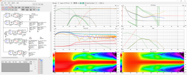
Wow!. Just tried passive implementation of XO between front and side woofers and it pretty much fixed that dip.
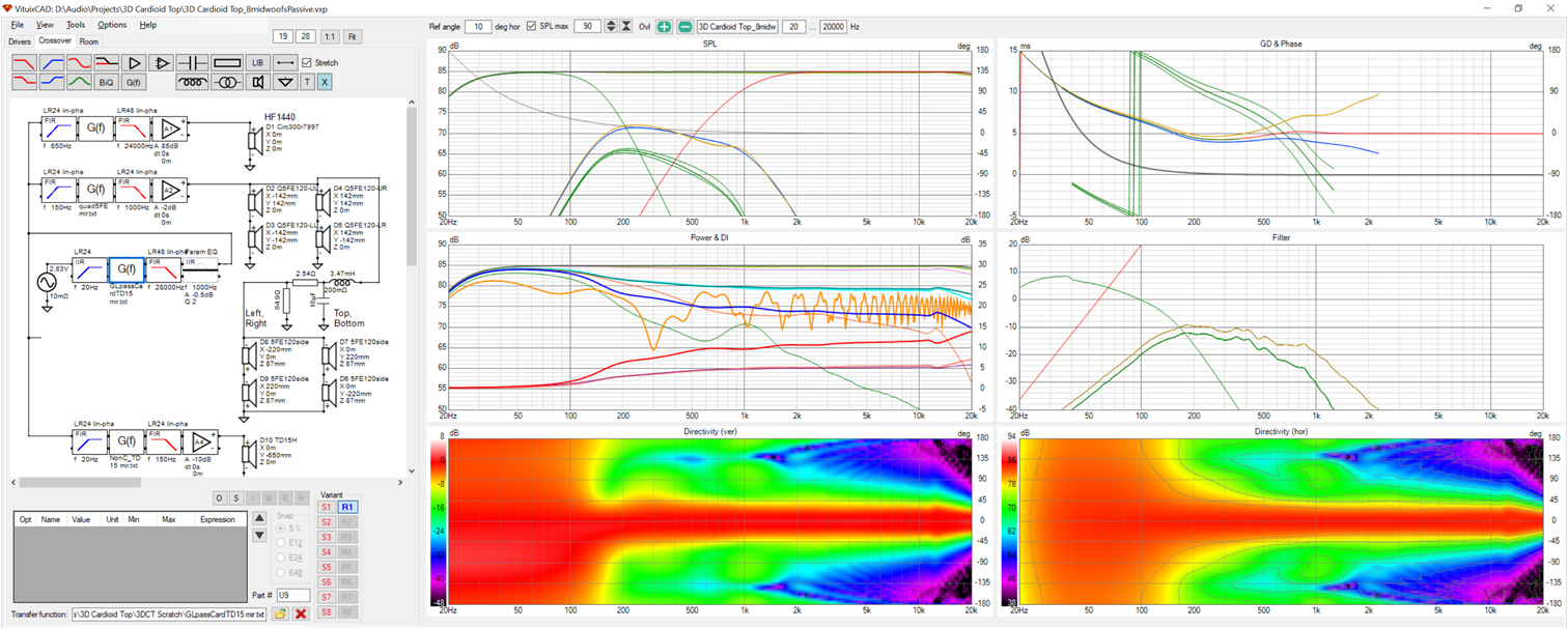
Double thanks to Kimmo. He showed how some time ago. Now Vituix library supplies 2nd order, 8 ohm LC filter on request, then a 1.6 db Lpad
As to that slot resonance, we'll have to see. I'll have some damping on hand...
Wow!. Just tried passive implementation of XO between front and side woofers and it pretty much fixed that dip.
Double thanks to Kimmo. He showed how some time ago. Now Vituix library supplies 2nd order, 8 ohm LC filter on request, then a 1.6 db Lpad
Attachments

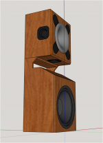
I think this construction would have a much better chance of allowing the bottom midwoofer to do its job

The bottom midwoofer's view to the lower front hemisphere is unrestricted. A thick layer of felt on the top and slant front of the woofer cabinet may be necessary.
I will have an angle bracket screwed to the back lower edge of the Top that catches on the shelf to prevent the Top from toppling forward.
And I need to change the waveguide to one with no rollback integrated into the baffle....
Attachments
Someone asked how to get from ATH to Vituix
Here are some bread crumbs.
follow the ath ->abec -> vacs path
in vacs, with a polar map showing, click "graphs" then "convert curves to contour"
You will get a plot of the directivity files you want to import into Vituix
click that graph and then "export data" and save to some directory
name the first file something like "WGname_hor"and vacs will fill it with the directivity files
the only problem will be their names. they will need to be renamed to include the angle in the file name as Vituix expects
you will get WGname_oo1.txt, WGname_002.txt ... and need to change them to WGname_hor_0, WGname_hor_10, WGname_hor_20 and so forth for steps of 10 degrees
and then create a 2nd set, if the WG is axisymmetric, where all the "hor"s have been changed to "vert" or from the vert polar map if its not axisymmetric
That renaming is pretty onerous except for a renaming utility that @fluid gave me
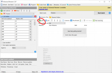
Advanced Renamer - Free and fast batch rename utility for files and folders
Using this tool is pretty simple.

fill in the list replace table on the left side of the screen (and save it for reuse). ATH's consecutive numbers get replaced with the angles in 5 or 10 degree steps as you specified back in the ATH script.
Then follow the Add/files method under the red circle in the middle of the screen to select the files to be renamed, (first all the "hor" files and again for the "vert"s. After selecting files click "start batch"
then just point Vituix at these files in its Drivers tab
Here are some bread crumbs.
follow the ath ->abec -> vacs path
in vacs, with a polar map showing, click "graphs" then "convert curves to contour"
You will get a plot of the directivity files you want to import into Vituix
click that graph and then "export data" and save to some directory
name the first file something like "WGname_hor"and vacs will fill it with the directivity files
the only problem will be their names. they will need to be renamed to include the angle in the file name as Vituix expects
you will get WGname_oo1.txt, WGname_002.txt ... and need to change them to WGname_hor_0, WGname_hor_10, WGname_hor_20 and so forth for steps of 10 degrees
and then create a 2nd set, if the WG is axisymmetric, where all the "hor"s have been changed to "vert" or from the vert polar map if its not axisymmetric
That renaming is pretty onerous except for a renaming utility that @fluid gave me
Advanced Renamer - Free and fast batch rename utility for files and folders
Using this tool is pretty simple.
fill in the list replace table on the left side of the screen (and save it for reuse). ATH's consecutive numbers get replaced with the angles in 5 or 10 degree steps as you specified back in the ATH script.
Then follow the Add/files method under the red circle in the middle of the screen to select the files to be renamed, (first all the "hor" files and again for the "vert"s. After selecting files click "start batch"
then just point Vituix at these files in its Drivers tab
Attachments
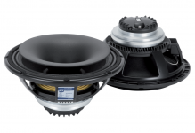
There might be an easier way to do this. A coax driver with a waveguide inside the woofer cone is what I've been making with waveguide plus rim drivers.
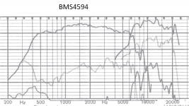
This is the RCF CX12N351
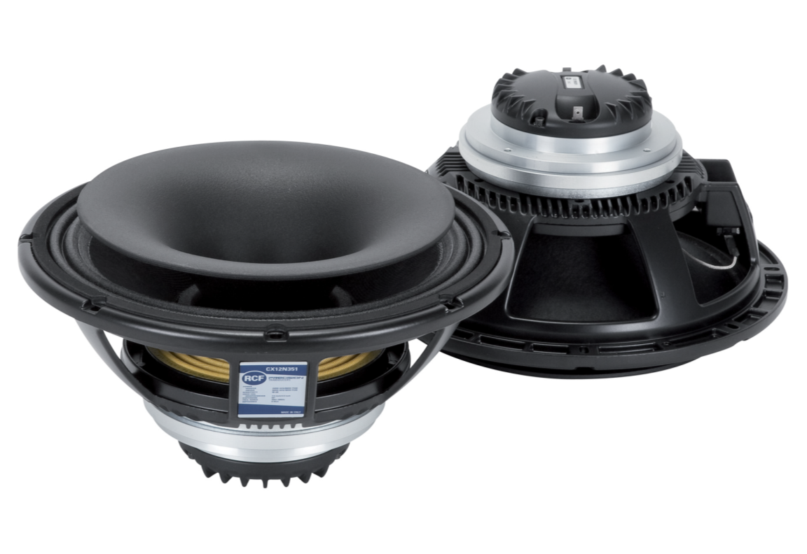
I saw this a while ago but what always held me back was the lack of smoothness in typical coax driver responses. But the RCF is better than most. And it has the 60x60 constant directivity pattern I'm looking for for my small room. Still I haven't heard an RCF coax or seen a review. Does anyone out there have any experience with them? I see that RCF makes box speakers using their coaxes that are highly regarded but still it would be a risk to commission a box construction based on this info alone.
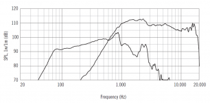
Here is the data sheet frequency response:
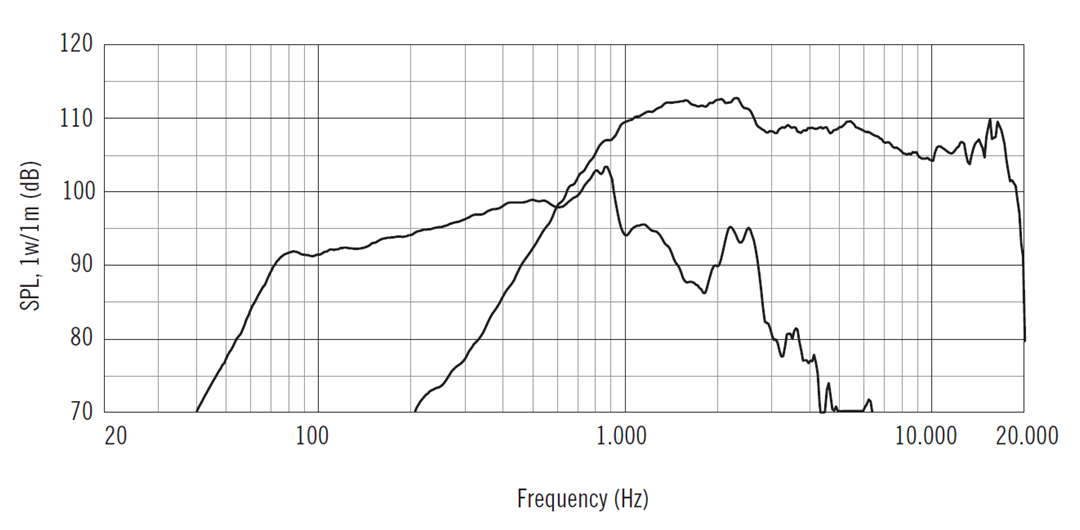
I think with FIR filtering - impulse response inversion - the response will flatten out nicely - at least until it approaches the limits of my hearing.
RCF doesn't publish any directivity data but I created a 4 hole rim driver model for a 15" coax - like I've been using with my ATH waveguide sim to approximate it. That model's response narrowed too soon so I switched to the 12" driver modeled with 8 holes at 45 degree intervals. At some point, I'll increase the model to 16 holes ...
I put the coax's woofer model together with a side woofer array on all 4 sides of the box. The side woofer array consists of 6 DMA58 2" drivers. There was less than 1 db change in response below 700 Hz depending on whether or not I modelled an 18 mm radius on side woofer baffle edges. These drivers cost about $12 each. 24 of them can keep the woofer's pattern under control past 105 db SPL. The equalization includes a high pass filter that limits the excursion required of the DMA58's. Below the high pass frequency now at 175 Hz, the response is monopole.
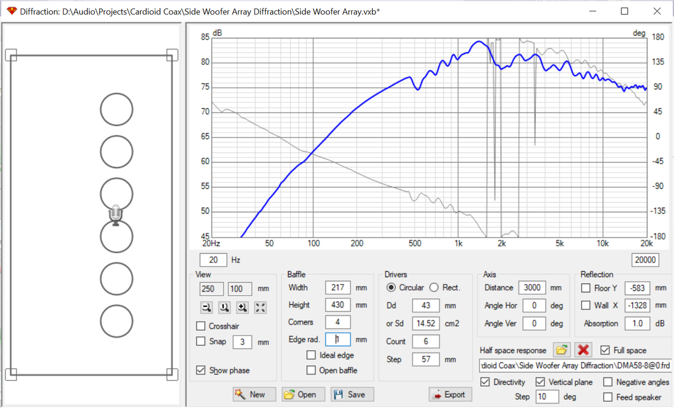
This is the Vituix simulation:
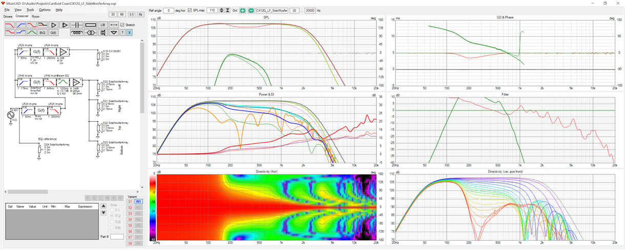
This doesn't include the HF because I don't have directivity for it yet. XO will be at/around 700 Hz. Note that at home levels bass can be flat to at least 35 Hz and thus is useable without subs for 2 ch music.
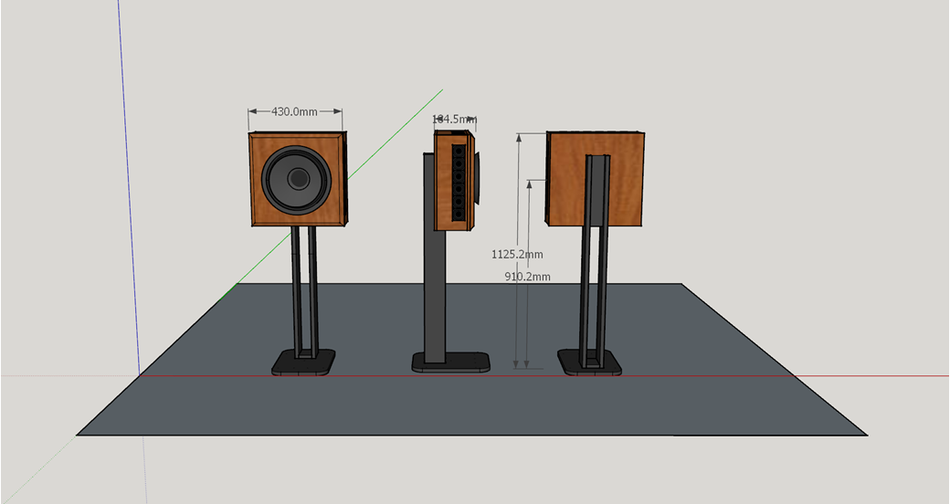
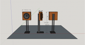
This what it would look like:
This design converts readily to passive cardioid by leaving out the side woofer arrays.
This meets my requirements for small footprint and extended pattern control. The model shows >10 db attenuation to the rear but only 6-8 db to the sides. I understand from D&D patent that may change based on box depth.
I'm hoping RCF is willing to share directivity data or at least cone profile with me. If not I can try to match the image using ATH.
This is the RCF CX12N351
I saw this a while ago but what always held me back was the lack of smoothness in typical coax driver responses. But the RCF is better than most. And it has the 60x60 constant directivity pattern I'm looking for for my small room. Still I haven't heard an RCF coax or seen a review. Does anyone out there have any experience with them? I see that RCF makes box speakers using their coaxes that are highly regarded but still it would be a risk to commission a box construction based on this info alone.
Here is the data sheet frequency response:
I think with FIR filtering - impulse response inversion - the response will flatten out nicely - at least until it approaches the limits of my hearing.
RCF doesn't publish any directivity data but I created a 4 hole rim driver model for a 15" coax - like I've been using with my ATH waveguide sim to approximate it. That model's response narrowed too soon so I switched to the 12" driver modeled with 8 holes at 45 degree intervals. At some point, I'll increase the model to 16 holes ...
I put the coax's woofer model together with a side woofer array on all 4 sides of the box. The side woofer array consists of 6 DMA58 2" drivers. There was less than 1 db change in response below 700 Hz depending on whether or not I modelled an 18 mm radius on side woofer baffle edges. These drivers cost about $12 each. 24 of them can keep the woofer's pattern under control past 105 db SPL. The equalization includes a high pass filter that limits the excursion required of the DMA58's. Below the high pass frequency now at 175 Hz, the response is monopole.
This is the Vituix simulation:
This doesn't include the HF because I don't have directivity for it yet. XO will be at/around 700 Hz. Note that at home levels bass can be flat to at least 35 Hz and thus is useable without subs for 2 ch music.
This what it would look like:
This design converts readily to passive cardioid by leaving out the side woofer arrays.
This meets my requirements for small footprint and extended pattern control. The model shows >10 db attenuation to the rear but only 6-8 db to the sides. I understand from D&D patent that may change based on box depth.
I'm hoping RCF is willing to share directivity data or at least cone profile with me. If not I can try to match the image using ATH.
Attachments


Last edited:
- Home
- Loudspeakers
- Full Range
- Full range line array for wall or corner placement