what needs to be taken into account is the directivity of the waveguide
my waveguide has a high pass at 700 hz.
The baffle is behind the waveguide. Its the waveguide response beyond 90 degrees that interacts with the baffle. Look at the waveguide response above 700 Hz at angles between 90 and 180 on the graph I posted this morning. Its down pretty far in that region. That is what gives me hope.
Diffraction of radiation already down 10-20 db might not be terribly problematic. Its as much reflection from the baffle as diffraction from its edges.
If you integrate waveguide into baffle without rollback, its radiation at 90 degrees that interacts with the edge of the baffle. That is where roundover pays big dividends, I guess.
But these are two different cases. Both deserve to be investigated.
I'm afraid that in this case the woofers output would reflect and diffract on the waveguide since it is still physically big obstacle at the xo wavelenghts. Either the woofers or the tweeter output has something to diffract on, in most if not all cases. Maybe it is not that much of a concern since the xo is already pretty low.
Last edited:
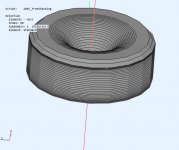
Maybe you already know but this is not the same thing, that is extending the rollback further, mabat's sim I posted is the equivalent of the the one where you tried to add a baffle. The freestanding guide needs some breathing room behind it or the baffle needs to be a continuation of the rollback to minimize diffraction.Here is the original profile and how I modified it
Yes 🙂Once you put a baffle behind the waveguide (with round-over), there will be diffraction from that baffle. I think that's the point made by fluid.
If you integrate the waveguide in a baffle with round-overs on the baffle (instead of the waveguide) the results would be better than the waveguide with round-over on top of a baffle. (as shown by fluid)
Even on the best baffled waveguides an extra roundover on the edge improves the evenness of the off axis response so you cannot discount the effect entirely from narrower directivity. The same thing can be seen with the shape of wesayso's array baffle and enclosure. The TC9 does get narrower with frequency and it still has a positive effect.Its the waveguide response beyond 90 degrees that interacts with the baffle. Look at the waveguide response above 700 Hz at angles between 90 and 180 on the graph I posted this morning. Its down pretty far in that region. That is what gives me hope.
I posted this quote from Wayne Parham in another thread. This is my reasoning too.
"The ones that tend to be most interested in edge diffraction - beyond the baffle step - those that are concerned with the more subtle effects tend to be the same designers that are interested in directivity and power response smoothness, e.g. uniformity of the reverberant field".
The freestanding guide is good at reducing the effect of the woofers on the pattern of the waveguide but that is only of benefit if the waveguide response itself is intact.
If I was going to make a speaker like your latest renders I would be using a guide designed to terminate in the baffle and look at bandpass ports for the woofers like the PK CMI as at the crossover frequency they should be invisible.
The other option is this sort of arrangement shown by aragorus but practically making it in any reasonable size seems difficult, particularly with the side and top woofers.
Yes, Aragorus, practicalities aside, has shown an idealized shape. It looks like it would be suitable for a phase plug for a large woofer or bass horn. You could even make it cardioid with a woofer firing out the back, if you were to push practicalities further aside.
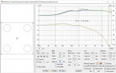
Vituix easily shows how significant the baffle edge diffraction is for the woofers in the current design.
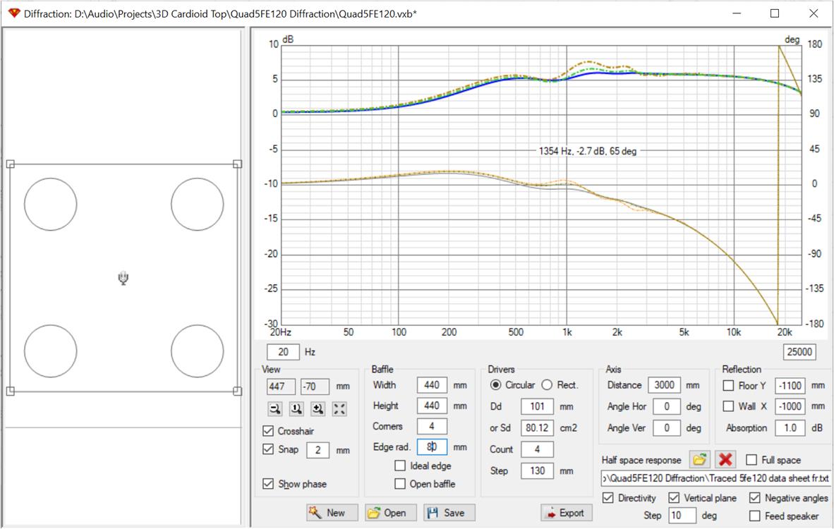
I overlaid baffle step responses for 0, 40 mm and 80 mm edge radius. Below 700 Hz, there is less than half a db of difference and in a region where the room and boundaries have a larger effect.
You may recall my prior approach was bandpass woofers firing through the flat part of the waveguide. I may go back there. Or I may go further back to a waveguide terminated in the baffle, again with bandpass ports. It seems thought that choosing between the current approach and those is like choosing one's poison. Both have aspects of their performance that are impractical to validate in simulation. On the other hand, there is more I can do in simulation before I'm faced with that choice. What steered me to the current approach was the ABEC simulation that showed that the baffle behind the rolled back waveguide had very little effect on its response. I found those sims. My next step is to redo them more rigorously and for the current waveguide size.
Vituix easily shows how significant the baffle edge diffraction is for the woofers in the current design.
I overlaid baffle step responses for 0, 40 mm and 80 mm edge radius. Below 700 Hz, there is less than half a db of difference and in a region where the room and boundaries have a larger effect.
You may recall my prior approach was bandpass woofers firing through the flat part of the waveguide. I may go back there. Or I may go further back to a waveguide terminated in the baffle, again with bandpass ports. It seems thought that choosing between the current approach and those is like choosing one's poison. Both have aspects of their performance that are impractical to validate in simulation. On the other hand, there is more I can do in simulation before I'm faced with that choice. What steered me to the current approach was the ABEC simulation that showed that the baffle behind the rolled back waveguide had very little effect on its response. I found those sims. My next step is to redo them more rigorously and for the current waveguide size.
Attachments
Last edited:
It's the waveguide that would suffer from diffraction in the above situation. We weren't worried about the woofers.
there was some discussion of the woofers. thought it was worthwhile to quantify it.
Now we are left with the effect of the baffle on the waveguide's pattern which is next on my list. I would like to quantify that as well as I'm willing to accept some small compromise if it simplifies implementation because as we both see from looking at SH50 measurements a speaker doesn't have to be perfect to sound very good.
Now we are left with the effect of the baffle on the waveguide's pattern which is next on my list. I would like to quantify that as well as I'm willing to accept some small compromise if it simplifies implementation because as we both see from looking at SH50 measurements a speaker doesn't have to be perfect to sound very good.
Last edited:
there was some discussion of the woofers. thought it was worthwhile to quantify it.
Now we are left with the effect of the baffle on the waveguide's pattern which is next on my list. I would like to quantify that as well as I'm willing to accept some small compromise if it simplifies implementation.
The only thing to look at with the baffle diffraction from the woofers is to see if the baffle peak dip affects the crossover. With a steep XO at 700 Hz that is unlikely. In an active DSP system the bump could be removed with EQ. I would say that 36mm is good enough for the waveguide with 50mm or more being slightly better. Chamfers or roundovers are close enough to each other to choose based on looks and ease of construction.
The woofers themselves can act as a source of interference that will eclipse the effect of the baffle so ports of some kind can help with that but bring their own problems.
You have enough ability with Ath to design your own baffled guide that gives close enough performance to the freestanding one. If you could only print an STL someone gave you it would make more sense to try slapping it on a baffle. I have no idea what sim you ran that made you think there is no issue, but just looking at it should make it obvious that it is not optimal.
There has to be compromise somewhere and making some for an easier build makes the most sense 🙂
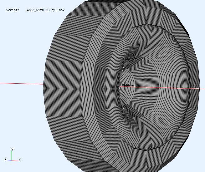
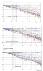
I've redone my sims and the results aren't as bad as I feared, given mabat's results but not as good as I had hoped.
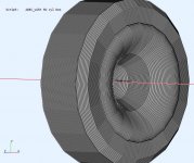
I simulated a straight edged cylindrical box and a beveled edge cylindrical box with a 20 mm bevel. This allowed me to stay asymmetrical and avoid all the meshing problems fluid has noted.
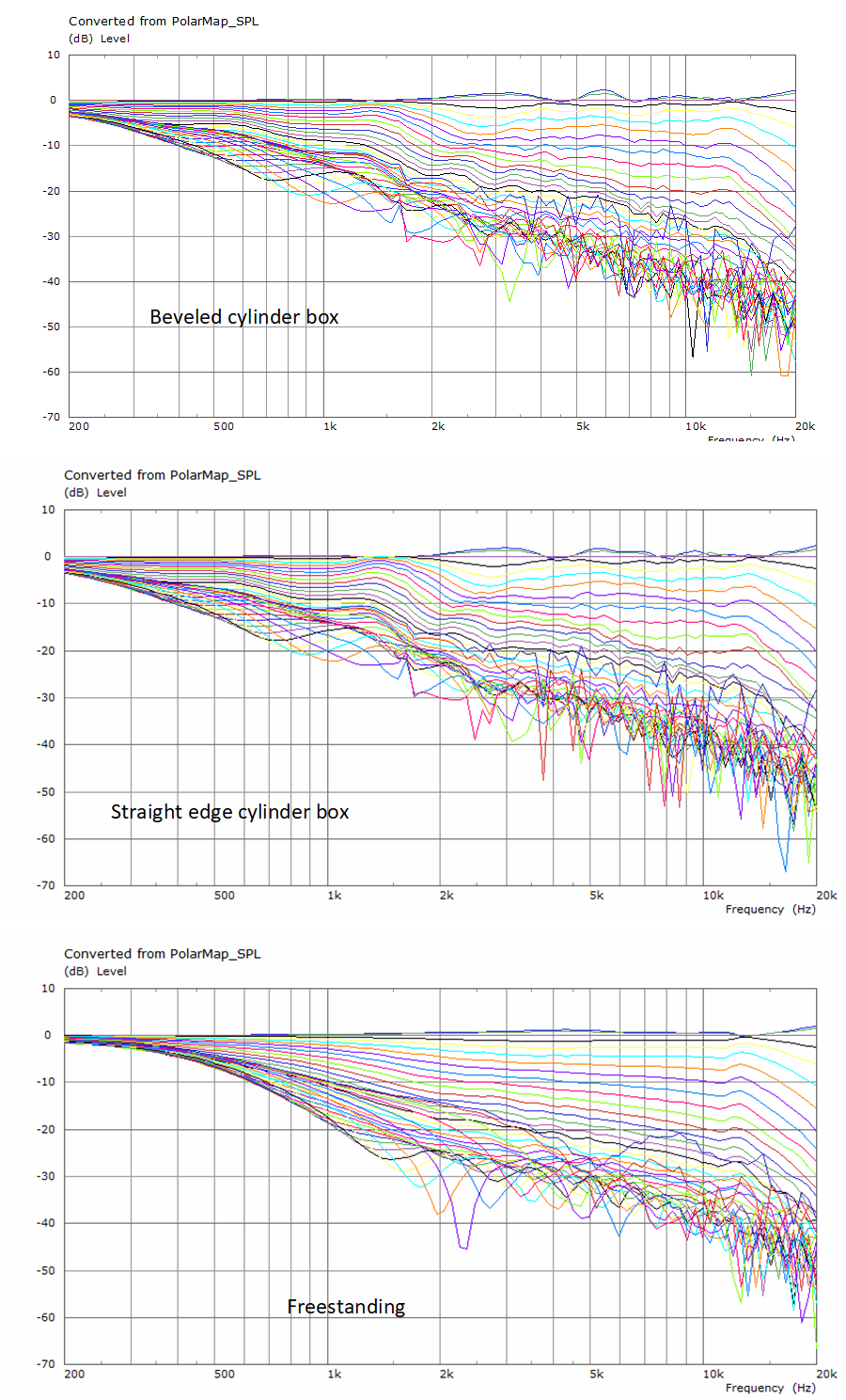
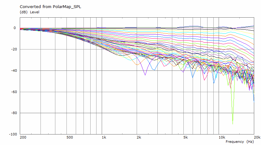
I'm not terribly surprised at the results that the response is affected below 2 khz. That is where the waveguide pattern is widening. I am surprised somewhat that results above 2 khz are affected. Granted its only a db or so but still there shouldn't be any radiation going backwards to return from the baffle.
Would a roundover instead of a bevel be any better? Another cup of coffee and perhaps my brain will be up to the challenge.
Would a rectangular box be better than cylindrical? I think so but that is much harder and longer to simulate.
I think I know what happened when I was misled by earlier sims. I did those in the same directory as the free standing sim without first deleting the results file. I've since noticed that when you do this, abec doesn't reload all the project files so I wasn't simulating what I thought I was; likely just repeating the free standing sim.
I simulated a straight edged cylindrical box and a beveled edge cylindrical box with a 20 mm bevel. This allowed me to stay asymmetrical and avoid all the meshing problems fluid has noted.
I'm not terribly surprised at the results that the response is affected below 2 khz. That is where the waveguide pattern is widening. I am surprised somewhat that results above 2 khz are affected. Granted its only a db or so but still there shouldn't be any radiation going backwards to return from the baffle.
Would a roundover instead of a bevel be any better? Another cup of coffee and perhaps my brain will be up to the challenge.
Would a rectangular box be better than cylindrical? I think so but that is much harder and longer to simulate.
I think I know what happened when I was misled by earlier sims. I did those in the same directory as the free standing sim without first deleting the results file. I've since noticed that when you do this, abec doesn't reload all the project files so I wasn't simulating what I thought I was; likely just repeating the free standing sim.
Attachments
They simulate to be virtually the same unless a very high resolution is used.Would a roundover instead of a bevel be any better?
Probably but the issue is the abrupt change in curvature at the baffle.Would a rectangular box be better than cylindrical?
This is what the HF1440 guide I sent you before looks like in cabinet with a 36mm roundover right on the guide as shown before. Above 5k you can see the mesh instability creep in as this is a full 3D sim not circsym.
Attachments
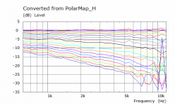
Despite the apples to oranges issue, I loaded the directivity files of the beveled cylindrical box into the Vituix simulation for the 8-woofer, square baffle box to get a feel for the effect of its imperfections at the system level.

Normalizing to the presumed 10 deg H listening axis, I see a +1.5 db, -1 db variation over a 20 degree H listening window.
Equally if not more disturbing is a 2 db bump in the power response and DI around 1.5 khz and a slightly smaller one around 3 khz.
Perhaps as Kimmo suggests, the box shape (including the waveguide and RO vs terminated in baffle) can or must be tuned to optimize the directivity. I think terminating the waveguide in the rounded over baffle will definitely look better at this level but then I'll also have to deal with a cancellation null from woofer radiation returning from the CD's phase plug....
Attachments
Yes, will do so once the drivers arrive (fingers crossed for end of September) 🙂
Opened a new thread here to document my progress with this project:
Murphy's Corner Line Array project | Audio Science Review (ASR) Forum
This is true. A fully freestanding guide is more flexible as it is unaffected by the baffle and enclosure so they can be optimized for the woofer and cross over region.Perhaps as Kimmo suggests, the box shape (including the waveguide and RO vs terminated in baffle) can or must be tuned to optimize the directivity.
I don't think this is much of an issue in practice if you look at Earl's Summa or the JBL M2 that Erin has just posted measurements of, there is no significant evidence of the woofer doing significant damage from reflections off it.I think terminating the waveguide in the rounded over baffle will definitely look better at this level but then I'll also have to deal with a cancellation null from woofer radiation returning from the CD's phase plug....
I produced the same diameter waveguide without a rollback and repeated the simulation in the beveled cylindrical box. the woofer ports would be centered in the flat part of the baffle.
That is a 20 mm bevel. Looks like a 40 mm bevel would be better. Diameter would need to increase to support that.
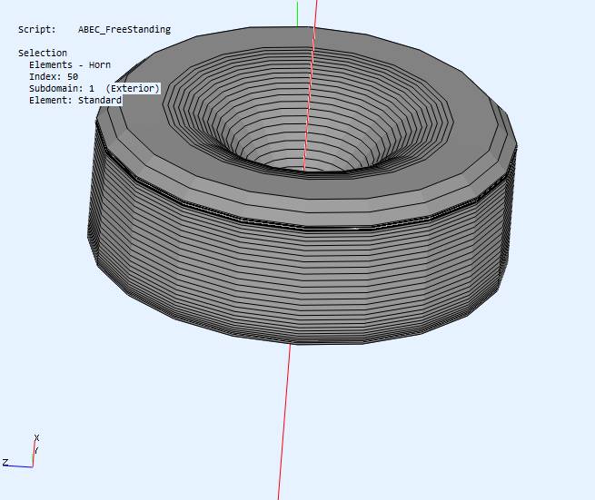
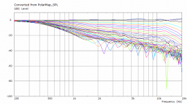
The abec simulation of the waveguide free standing, without a baffle:
abec with baffle and beveled cylindrical back/box:
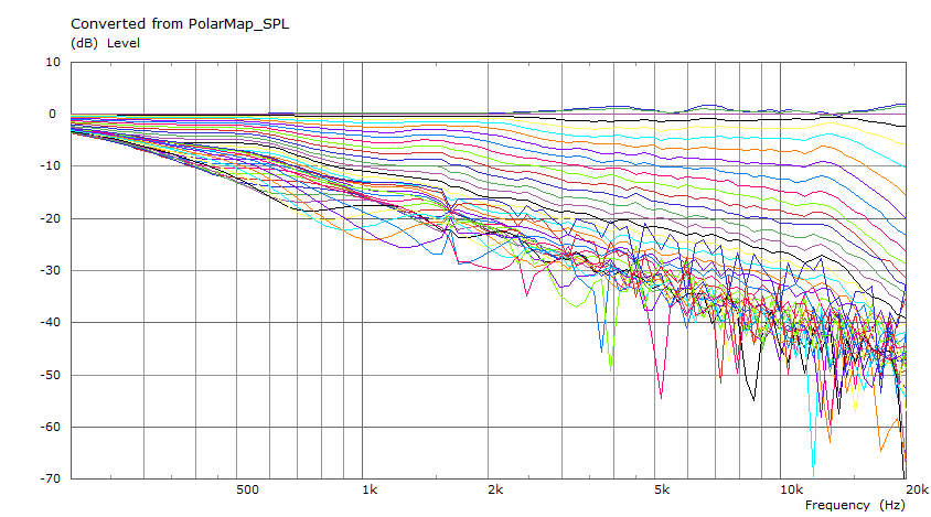
Its the slightly rising response off axis circa 1.5 khz that suggests to me a larger bevel would be better.
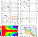
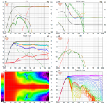
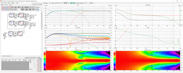
Finally, pointing Vituix at the directivity files, I get this response:
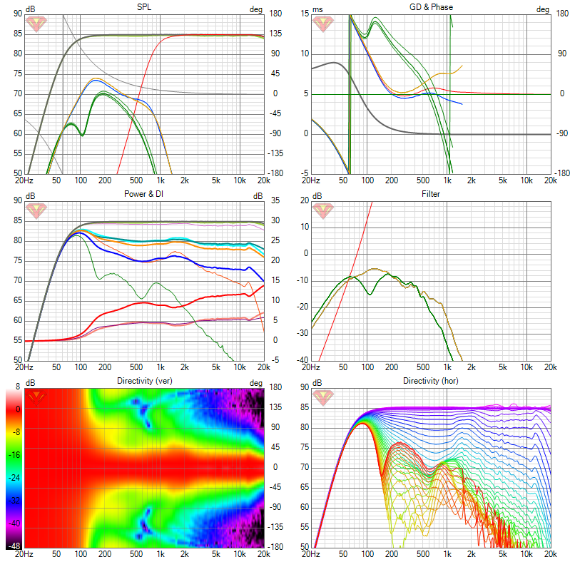
The power response and DI curves are smoother than for the rolled back waveguide but the polar maps show more pattern widening at 1.5 to 2 khz than I would like. Some of this, I think, is due to baffle step and will be reduced with a larger bevel or roundover. I could also make the waveguide larger to just fit within the rollback. Then I would have woofer ports within the waveguide.
At this point I would have to worry about a reflection null from the CD phase plug, just as in a MEH. The round trip travel distance is about .36m (on the axis instead of along the wall) which corresponds to a delay of just over 1ms. This suggests a dip or null around 500 hz, which is under the woofer's 700 Hz cutoff frequency.
That is a 20 mm bevel. Looks like a 40 mm bevel would be better. Diameter would need to increase to support that.
The abec simulation of the waveguide free standing, without a baffle:
abec with baffle and beveled cylindrical back/box:
Its the slightly rising response off axis circa 1.5 khz that suggests to me a larger bevel would be better.
Finally, pointing Vituix at the directivity files, I get this response:
The power response and DI curves are smoother than for the rolled back waveguide but the polar maps show more pattern widening at 1.5 to 2 khz than I would like. Some of this, I think, is due to baffle step and will be reduced with a larger bevel or roundover. I could also make the waveguide larger to just fit within the rollback. Then I would have woofer ports within the waveguide.
At this point I would have to worry about a reflection null from the CD phase plug, just as in a MEH. The round trip travel distance is about .36m (on the axis instead of along the wall) which corresponds to a delay of just over 1ms. This suggests a dip or null around 500 hz, which is under the woofer's 700 Hz cutoff frequency.
Attachments

I'm using a CD with response below 500 Hz. My plan is/would be to let just enough energy at 500 Hz pass through the CD in the right phase to cancel the reflection null/dip.
I was intrigued by conversations in other threads about CTC = 1.2 x WL at XO being optimal. This didn't seem right given my prior focus on reducing CTC so I decided to try it myself. I modelled a 2-way using my 300 mm axisymmetric round waveguide and a 12" woofer and played with CTC.
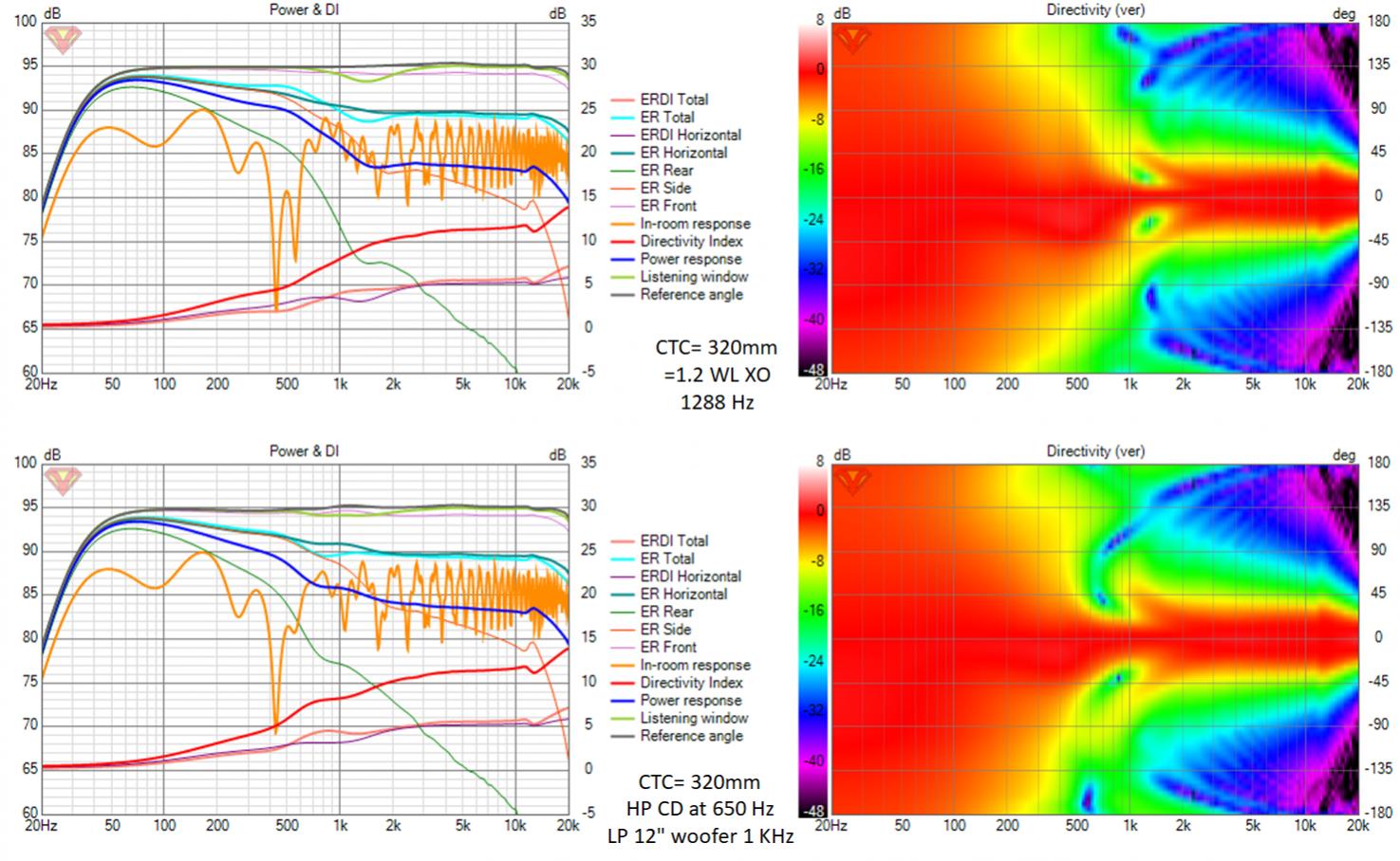
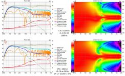
The top row of the drawing is with an LR4 XO at 1288 Hz which corresponds to CTC = 1.2 * WL at XO with a CTC of 320 mm.
The bottom row is with an overlap between CD and woofer. The overlap gives a better directivity match at XO. This one looks better to me. For neither case is the vertical polar map pretty but the power responses and DIs are fairly smooth.
Encouraged by the latter I worked a little harder on the model and XO and ended up with this:
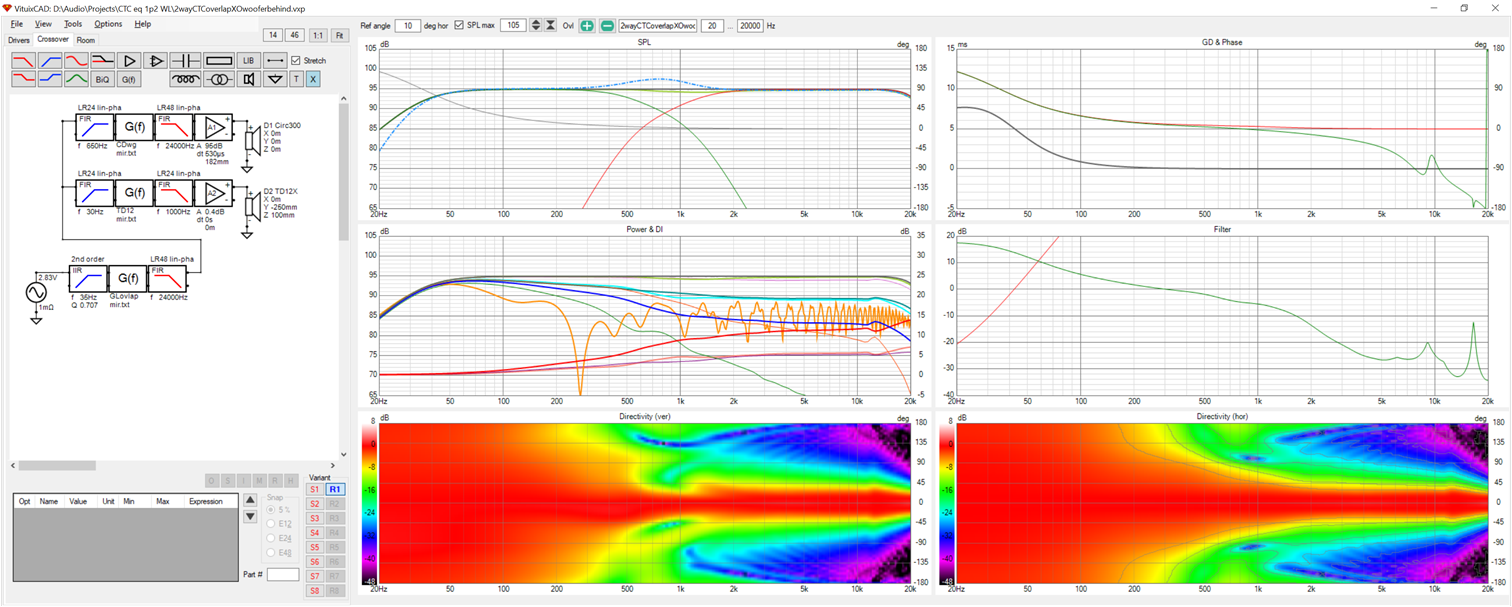
This model has the woofer behind the waveguide with some overlap. The waveguide will be free standing (on a stand) on top of the rounded over woofer box. I will likely put thick felt between the baffle and waveguide where this overlap exists; over a wider region if it helps. I'm not modelling the baffle so its effects are unaccounted for in this simulation.
This model has everything I was looking for except for high directivity below 500 Hz. Its so much simpler I have to consider which is easier: cardioid or convincing my wife to allow some room treatment?
The dashed blue line is the FR before correction by the global FIR eq. This flattens the response at XO and corrects the phase. There is excess phase to be corrected due to the setback of the woofer and me adding delay to steer the forward beam in the vertical direction.
The top row of the drawing is with an LR4 XO at 1288 Hz which corresponds to CTC = 1.2 * WL at XO with a CTC of 320 mm.
The bottom row is with an overlap between CD and woofer. The overlap gives a better directivity match at XO. This one looks better to me. For neither case is the vertical polar map pretty but the power responses and DIs are fairly smooth.
Encouraged by the latter I worked a little harder on the model and XO and ended up with this:
This model has the woofer behind the waveguide with some overlap. The waveguide will be free standing (on a stand) on top of the rounded over woofer box. I will likely put thick felt between the baffle and waveguide where this overlap exists; over a wider region if it helps. I'm not modelling the baffle so its effects are unaccounted for in this simulation.
This model has everything I was looking for except for high directivity below 500 Hz. Its so much simpler I have to consider which is easier: cardioid or convincing my wife to allow some room treatment?
The dashed blue line is the FR before correction by the global FIR eq. This flattens the response at XO and corrects the phase. There is excess phase to be corrected due to the setback of the woofer and me adding delay to steer the forward beam in the vertical direction.
Attachments
Last edited:
Not sure I really follow the text of what you tried but the last graph looks to have a pretty nice response. I believe that would be a good sounding speaker everything else being equal.
Whether the difficulty in construction or increased cost of extra drivers etc. is worth it to extend the directivity I don't know.
Whether the difficulty in construction or increased cost of extra drivers etc. is worth it to extend the directivity I don't know.
Yes, that is the thing. It is outstandingly simple but should sound good; it just lacks the directivity down low that eases room placement and reduces/eliminates need for boundary treatment. Its good to know what it costs to get that directivity. The simplicity without the directivity calls the worth of that directivity into question, even for me.
As to what it is more clearly: Its my 300 mm diameter waveguide with rollback in a cradle sitting on top of TD12X woofer box with the woofer as close to the top of the box as possible. The cradle allows some fore/aft adjustment of the waveguide and some up/down adjustment to allow the waveguide to overlap the woofer a little.
How much overlap? I get the best response with a CTC of 250mm. At this CTC, the lip of the waveguide would overlap the middle of the surround roll by 30 mm. It (really just the vertical directivity near XO) only degrades slightly without that overlap. The question that isn't answered by Vituix is how the proximity of the waveguide affects the woofer's pattern (and vice versa but not anticipated to be problematic)
I would build the woofer box with the TD12 rear mounted and the cutout 30 mm less than the sqrt(Sd/pi) in radius - slightly bandpass. Then I design the cradle for the waveguide to drop the lip of the waveguide down over the edge of the woofer box to meet the edge of the opening. Perhaps I use some felt on the lower rollback of the waveguide...
That is what passes for a plan today; will it survive the first measurement?
Last edited:
Even a small gap between the freestanding guide and baffle woofer is enough to have virtually no effect on the waveguide.The question that isn't answered by Vituix is how the proximity of the waveguide affects the woofer's pattern (and vice versa but not anticipated to be problematic)
2 way waveguide speaker build ABEC modelling
The woofer would suffer a little from the proximity of the waveguide but keeping the crossover as low as possible and using some absorbent felt in the rollback at the bottom should minimize any issues.Perhaps I use some felt on the lower rollback of the waveguide...
When I posted this 2-way, I knew I was moving in the direction of ground you had already tread but I didn't recall you had ABECed the same thing, less the overlap.
I have simulated quite a lot of things now 🙂 A Paraline is the latest thing I want to try as I can see how it could potentially be a solution to a central driver for an expanding array.I didn't recall you had ABECed the same thing, less the overlap.
- Home
- Loudspeakers
- Full Range
- Full range line array for wall or corner placement