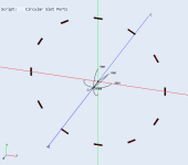
Here it is it worked doing it all as one, if you wanted to play with weights etc. then you could do each one separately. I made this by drawing a rectangle of the right size in Fusion and making a circular pattern of it, meshing this in gmsh at 5mm and importing.
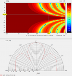
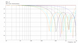
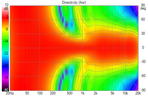
The frequency is 20Hz to 2K as really much beyond 500Hz is getting lobey. Vituix data attached. That is infinite baffle so use diffraction tool in Vituix.
The 20 deg pattern point is at about 555Hz as can be seen from the Polar.
H V and Diagonal are all the same so just mirror in Vituix.
There is no symmetry used as it wasn't really necessary and would have taken longer to CAD and mesh. The ABEC project is attached, it will import into Akabak but the observation planes end up wrong and the scaling can get messed up. I find it easier to do things from scratch in Akabak as it takes longer trying to undo the stuff that is wrong.
To see what was done look at the solving text file, you will see the frequency range defined the number of frequencies, whether any symmetry is being used and the mesh frequency (which only matters if using ABEC's own meshing).
Then the Mesh File is scaled with it's alias M1
The exterior subdomain is created as the only one as there is effectively nothing behind the baffle.
The Element for the the ports is created and named, assigned a unique number and linking the mesh alias and which tags are used.
The driving elements are labelled and referenced
The Infinite baffle plane is defined
The observation script links to the driving elements and set out the required spectra to be calculated, the parameters are set and given numbers to reference
Attachments
As a system with more dynamic potential than a fractal of straight expanding array but with some of their directivity traits I find it quite attractive.
It would need to be stretched far more in a vertical direction to make it come closer to array performance. I do agree, it would help to design a waveguide specific for this goal as it would be an easier match. An elliptical shape would make sense I guess.
Personally, I'd use just enough drivers horizontally to try and match that horizontal pattern, Having drivers mounted wider than the waveguide makes no sense to me. as all it would do is limit the horizontal beam in pattern control of that driver set. It might even lead to bigger problems once we look at off axis data in the horizontal plane. What we see isn't exactly what we get when more than one driver is used. Vituix calculates it from a mic standpoint, move the mic and it recalculates the pattern from that point. Not a problem with a single driver, way different with multiple drivers in a pattern in that direction.
As said, the biggest gripe I have with it that this narrowing is happening in 2 directions. I don't think that is needed or even desirable.
Last edited:
If really narrow but controlled vertical is to be prioritized then a full line or tall narrow speaker is needed there is no getting around that. I have one of those that works well I don't want to build another one, yet 🙂
I like the idea of using 4 x 5" drivers in an arrangement to see what can be done with those there should be enough flexibility to do something useful with them.
The concentric ring behaves a just like an axisymmetric source below the point where it starts to lobe, it really is the same in every direction, that is why I only posted the horizontal, every other graph is the same just with a different label.
In an axisymmetric device it has to shrink or grow in both directions at the same time it cannot be otherwise. That is why matching it with a ring makes conceptual sense as the patterns are similar, what makes less sense is trying to force it to do something it doesn't want to which then makes the polar shrink and grow.
But it is easy to see it is way more narrow that the waveguide where the crossover point is. Thus matching it to the waveguide could only be done if the ring were smaller in diameter. But by then it would be inside the guide itself (Synergy anyone?) 😉.
I'm still looking at this from a conceptual growing array aspect, maybe I shouldn't. But it isn't a successful continuation of the horn either. At least, not quite yet.
I'm still looking at this from a conceptual growing array aspect, maybe I shouldn't. But it isn't a successful continuation of the horn either. At least, not quite yet.
Last edited:
Thanks, fluid! I have some catchup/followup to do.
I think I'm between a rock and a hard place regarding the narrowing. If I fix the narrowing, the floor reflections get worse. The issue is the 60 degree waveguide but going to an elliptical 60H40V or 80H40V would not be without issues. I don't want to go wider (that is Mark100 territory 🙂) so it would shrink vertically, requiring a cross over to the rim slots the square of the pattern ration higher. That might well work but I've been wondering if the rim array and waveguide can't simply be tilted back 10 degrees. With a one piece rim array model, that is easy to try. I was lying in bed doing the trig in my head to figure the Z position for each slot. I got up to find I don't need to do that!
I think I'm between a rock and a hard place regarding the narrowing. If I fix the narrowing, the floor reflections get worse. The issue is the 60 degree waveguide but going to an elliptical 60H40V or 80H40V would not be without issues. I don't want to go wider (that is Mark100 territory 🙂) so it would shrink vertically, requiring a cross over to the rim slots the square of the pattern ration higher. That might well work but I've been wondering if the rim array and waveguide can't simply be tilted back 10 degrees. With a one piece rim array model, that is easy to try. I was lying in bed doing the trig in my head to figure the Z position for each slot. I got up to find I don't need to do that!
But it is easy to see it is way more narrow that the waveguide where the crossover point is. Thus matching it to the waveguide could only be done if the ring were smaller in diameter. But by then it would be inside the guide itself (Synergy anyone?) 😉.
Clearly the rim array diameter has to shrink to widen the beam. Our only not_bad simulation was with the diameter 42 mm greater than the wg. With the abec model its dia is 5mm greater, which might be close enough. The bad model sim of this did show great benefit from the reduced ctc.
Matching diameters should be sufficient for a directivity match at least at the pattern control limit. we shall see shortly
With this kind of experimenting, it could even be useful to get the slots inside the waveguide and observe the effects of it on higher frequencies. We may be far enough from the throat for it to not be that detrimental.
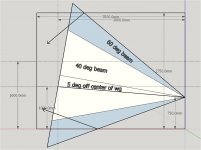
tilt back geometry
Here is the geometry for a tilted back 60 degree waveguide with the array center lowered to 750mm. The floor ceiling reflections mostly miss the head of a seated listener at 3m or so. A standing listener is not so fortunate.
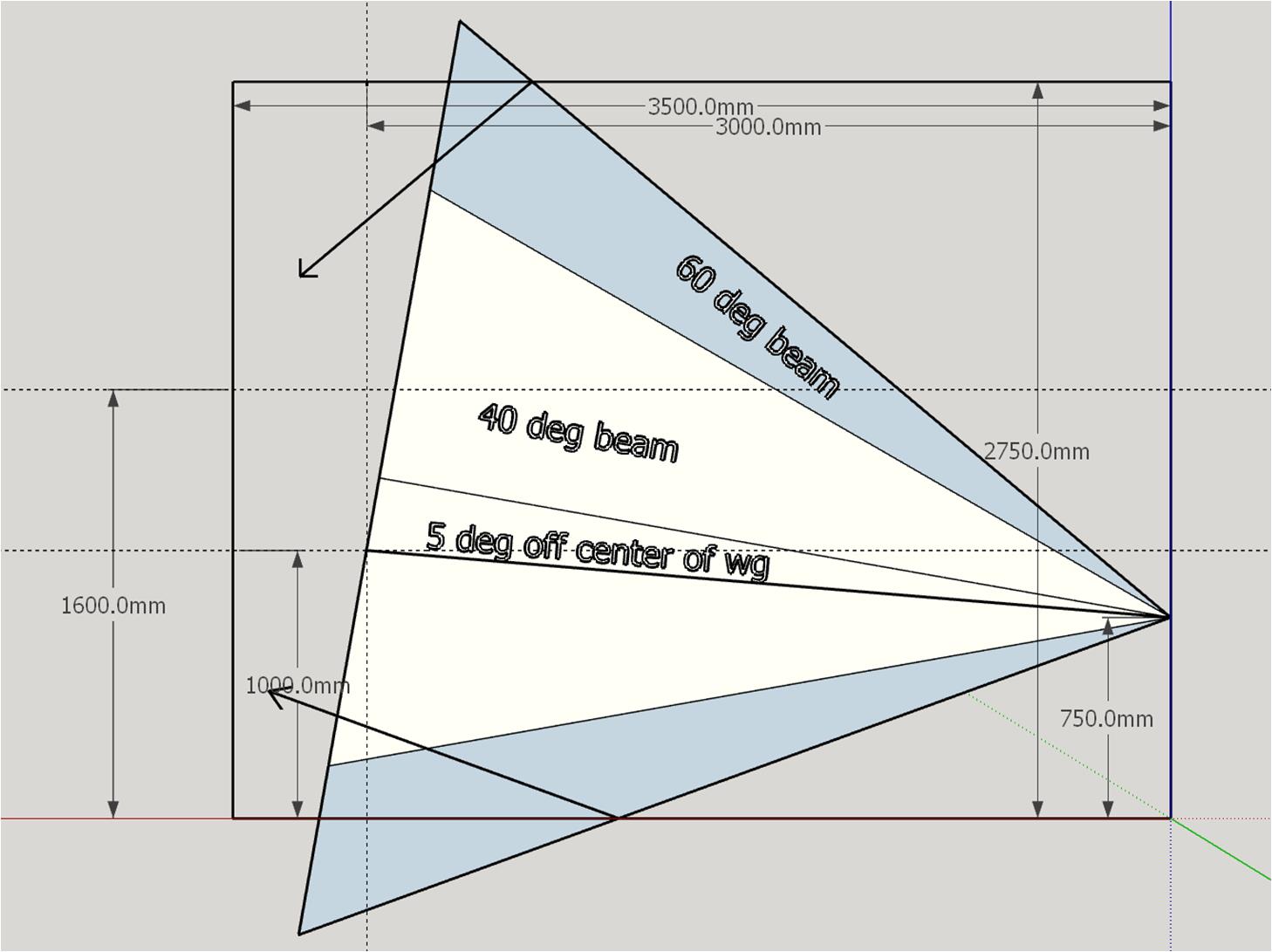
This seems like it would help. I'm visualizing a gimbal mount for the free standing waveguide and rim array.
Here is the geometry for a tilted back 60 degree waveguide with the array center lowered to 750mm. The floor ceiling reflections mostly miss the head of a seated listener at 3m or so. A standing listener is not so fortunate.
This seems like it would help. I'm visualizing a gimbal mount for the free standing waveguide and rim array.
Attachments
It would probably not have a big effect on the frequencies of that array.
However it can still affect the (higher) frequencies coming from the horn, just as it is favorable to use the roundover on the mouth of the horn.
However it can still affect the (higher) frequencies coming from the horn, just as it is favorable to use the roundover on the mouth of the horn.
I can see that tiling the array and wg is not a good idea 🙂
We still have the narrowing problem and its worse because it widens before it narrows

The reason is the rim array narrows too soon

if the only thing we can do to fix this is bring the drivers inside the waveguide, then we are in trouble because of the reflection from the CD's diaphragm.
We still have the narrowing problem and its worse because it widens before it narrows
The reason is the rim array narrows too soon
if the only thing we can do to fix this is bring the drivers inside the waveguide, then we are in trouble because of the reflection from the CD's diaphragm.
For some reason the images don't show.
If we have the slots out of the waveguide in the baffle or if we have them inside the waveguide will change their influence, but even in the baffle we run the chance of influencing the output of the waveguide. The timing of that disruptance is different, but it's still there i.m.h.o. If the waveguide is partially free from (in front of) the baffle we'd still have to find out what that does to the response.
As shown even a woofer in a baffle below a (baffled) waveguide has influence. Slots are smaller and their specific shape could alter the influence I guess.
Last edited:
Your images won't come up, maybe you did a basic edit on the post and the links were broken?
The only option with a ring of drivers is to make the ring smaller. To have the horizontal and vertical be different then the shape of the driver layout has to be different.
Edit: two minutes faster again 🙂
The only option with a ring of drivers is to make the ring smaller. To have the horizontal and vertical be different then the shape of the driver layout has to be different.
Edit: two minutes faster again 🙂
This is what I settled on after some fiddling. I optimized the polar maps rather than allowing narrowing in the vertical which would have improved the in-room response.

the waveguide plays 600Hz and up.
The rim array plays 200 Hz starts down gradually wih a Q=0.2 2nd order lowpass at 1 Khz and turns down sharply at 1156 Hz with LR48, all lin phase.
The td15 at floor level plays 20 Hz to 200 Hz
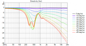
Equalized flat on axis anechoically, the room response vs offset:
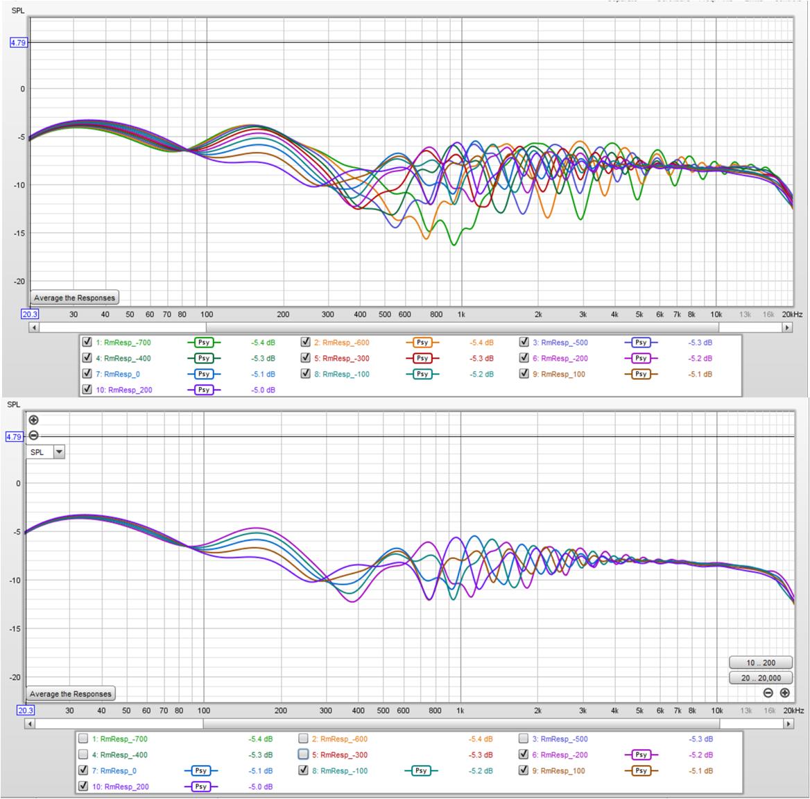
Its +/- 3 db for +/- 200 mm around the eq height and array center of 1m.
The widening around 1 khz is because the rim array response narrows too soon to be able to control that.
the waveguide plays 600Hz and up.
The rim array plays 200 Hz starts down gradually wih a Q=0.2 2nd order lowpass at 1 Khz and turns down sharply at 1156 Hz with LR48, all lin phase.
The td15 at floor level plays 20 Hz to 200 Hz
Equalized flat on axis anechoically, the room response vs offset:
Its +/- 3 db for +/- 200 mm around the eq height and array center of 1m.
The widening around 1 khz is because the rim array response narrows too soon to be able to control that.
Attachments
Images won't come up ? Probably something to do with sitting in draft window for several hours. But it does work for me when I open a new browser window.
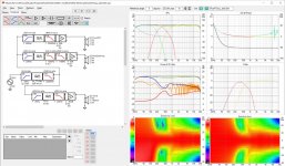
Here they are again:
first, the waveguide
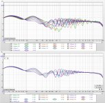
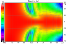
and then the rim array
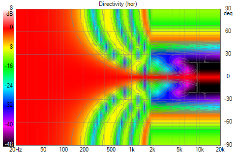
Here they are again:
first, the waveguide
and then the rim array
Attachments

Could you show the horizontals also, at one (on axis) height?
As in a 3 seat couch you'd be at different angles from the array horizontally. Just curious.
As in a 3 seat couch you'd be at different angles from the array horizontally. Just curious.
the question is what happens if we bring the rim array inside the waveguide. That is what appears to be needed.
Do we lose more from the holes disrupting the pattern and from reflection null than we gain from better directivity?
IIRC the wg is 135 mm deep. If the TC9 ports are at 3/4 of that depth, then reflection has roughly a 200 mm round trip. This corresponds to 400 mm null wavelength or about 860 Hz. This is in the CD - rim array overlap region so it will be masked to some extent. Also impulse response inversion equalization will cancel reflections. I'd like to see if that can be done! If that doesn't work, then there is the possibility of injecting an equal and opposite phase (to the reflection) signal into the CD's signal path.
With these abec models, it can be simulated and that is a necessary step
or maybe we simply go back to the smaller blended108 cirlular waveguide. It didn't have these issues; just lost pattern control sooner because of its smaller size
That is the concern and I hope to have some kind of an answer but so far working out the CAD modelling has proven trickier than anticipated. I have perhaps been too concerned with making it practical instead of just making it work enough to simulate and see the effect.the question is what happens if we bring the rim array inside the waveguide. That is what appears to be needed.
Do we lose more from the holes disrupting the pattern and from reflection null than we gain from better directivity?
I suspect something like that will ultimately work better as it has narrower vertical directivity and it could be made bigger but it would then get longer too.or maybe we simply go back to the smaller blended108 cirlular waveguide. It didn't have these issues; just lost pattern control sooner because of its smaller size
- Home
- Loudspeakers
- Full Range
- Full range line array for wall or corner placement