I think the problem of the rim array response narrowing too soon scales with the waveguide diameter. Horn pattern control frequency is proportional to its diameter. CTC is epsilon greater than the radius.
the blended108circ has a dia of 289mm which is the wavelength of 1190 hz
the hf1440 has a dia. of 472 mm, which is the wavelength of 723 hz
In both cases, right where I would eyeball the loss of pattern control from the graphs
I don't have a handy rule of thumb for ring radiator pattern but of course it scales with diameter. The question is how wide must it be half the wg dia,? 3/4?
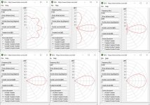
Somehow this train of thought reminded me that an MTM has a wider pattern with a 90 degreee crossover so I tried one:
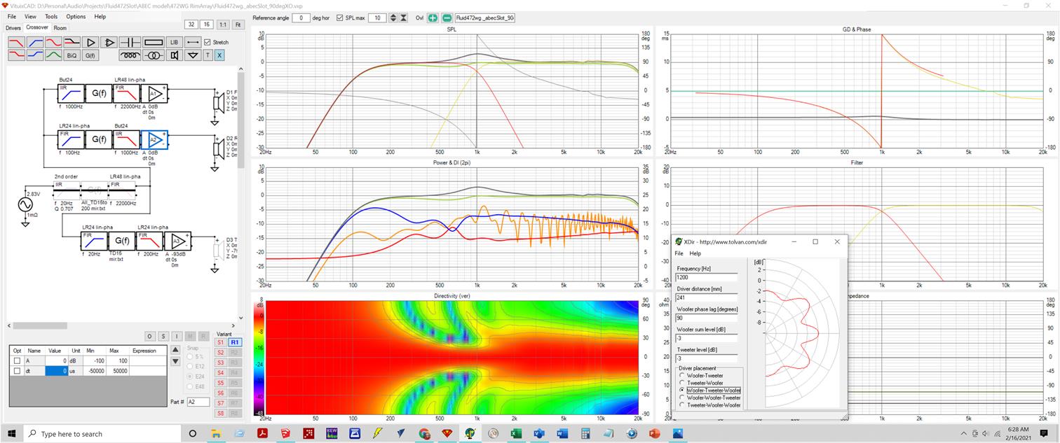
that is a 4th order IIR Butterworth at 1 khz, just the wg and rim array. It has the narrowing but the room response below XO has entirely different character and is much better behaved for large offsets
the blended108circ has a dia of 289mm which is the wavelength of 1190 hz
the hf1440 has a dia. of 472 mm, which is the wavelength of 723 hz
In both cases, right where I would eyeball the loss of pattern control from the graphs
I don't have a handy rule of thumb for ring radiator pattern but of course it scales with diameter. The question is how wide must it be half the wg dia,? 3/4?
Somehow this train of thought reminded me that an MTM has a wider pattern with a 90 degreee crossover so I tried one:
that is a 4th order IIR Butterworth at 1 khz, just the wg and rim array. It has the narrowing but the room response below XO has entirely different character and is much better behaved for large offsets
Attachments
the thought I had that got me out of bed early is that cancellation of an inside the rim array of mids would be relatively easy to tune as well as to simulate.
You play the mids only by themselves and observe the reflection null and measure its delay. You then play an inverted signal with the same filtering as the mids through the CD at that delay and adjust its amplitude to cancel the null. Now add the undelayed signal at full amplitude with XO and EQ filters to the CD's signal path and verify the crossover.
In Vituix, I would model this with a normal filter and amplifier chain driving the + terminal of the CD symbol and the cancellation filter and amplifier chain driving the - terminal of the speaker. In the "lab", I would use the mixer circuit in my MOTU sound card to add/subtract the cancellation signal.
Today this sounds very doable to me.
taking a moment to add and dial in the td15 at floor level:
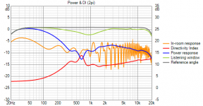
The global eq I did to flatten the overlap between TD15 playing up to 275 Hz and TC9s playing 100 Hz++ also flattened the rise at 1khz from the BW4 XO and flattened the phase full range. The listening window RMS, green line below, is +/- 15H, 20V
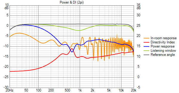
There is now a 3 db dip 10 degrees off axis
what I would like to do is make 5 degrees off axis my eq reference to split the difference across that 10 degree window but Vituix apparently only does 10 degree steps
The global eq I did to flatten the overlap between TD15 playing up to 275 Hz and TC9s playing 100 Hz++ also flattened the rise at 1khz from the BW4 XO and flattened the phase full range. The listening window RMS, green line below, is +/- 15H, 20V
There is now a 3 db dip 10 degrees off axis
what I would like to do is make 5 degrees off axis my eq reference to split the difference across that 10 degree window but Vituix apparently only does 10 degree steps
Attachments

Last edited:
the only thing not to like about the BW4 XO is that dip off axis just below the XO
the in-phase crossover doesn't have that dip but is more sensitive to the floor.
to get the best of both worlds, I think we need to be able to bring the TC9s inside the rim
the in-phase crossover doesn't have that dip but is more sensitive to the floor.
to get the best of both worlds, I think we need to be able to bring the TC9s inside the rim
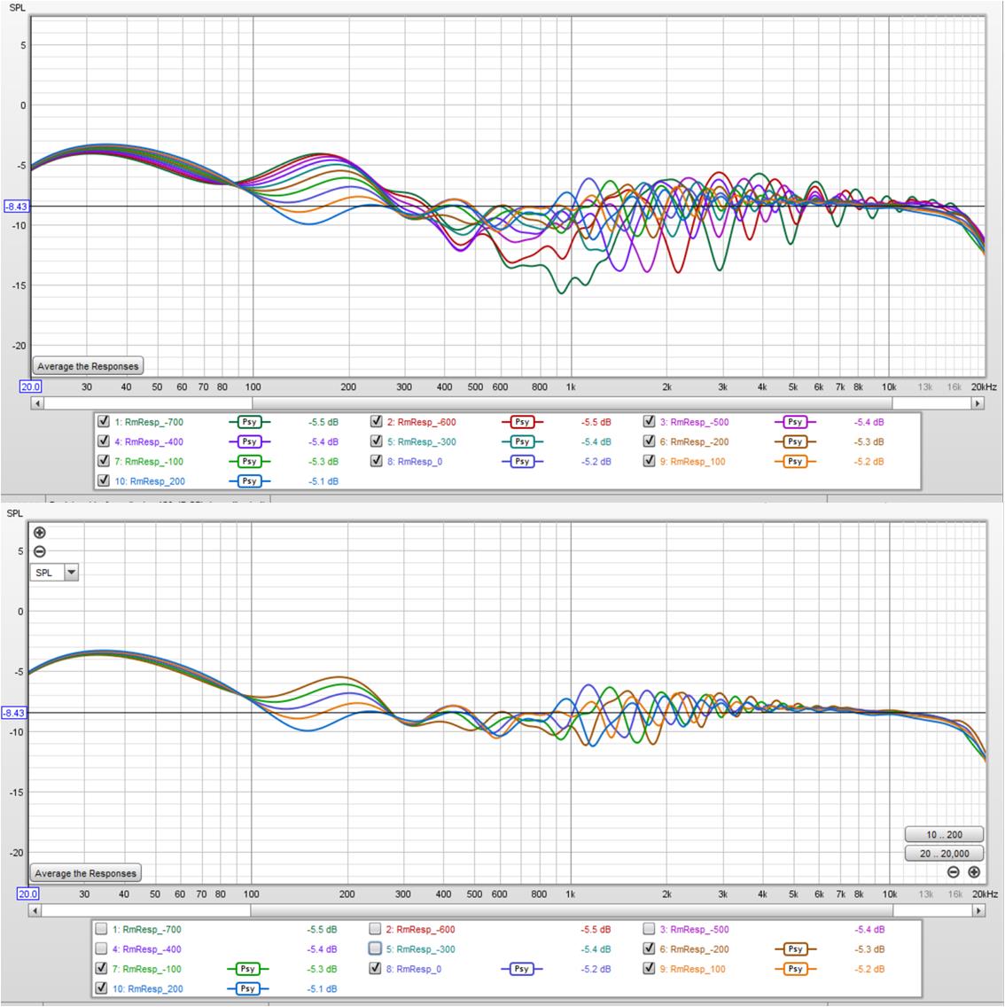
here is the horizontal line chart again, this time with 5 degree steps and using 5 degrees as the reference angle.
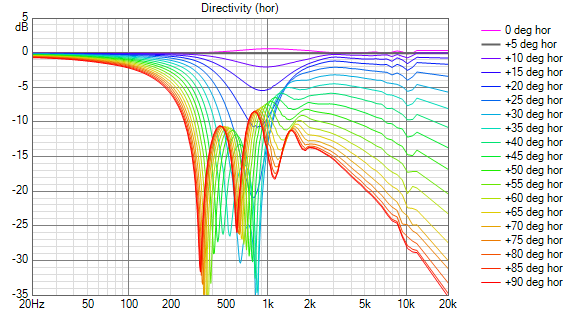
that looks more than good enough to cover the width of a couch
I noticed the in phase XO also has a dip below XO, but its half the depth or less...
I suspect this dip is due to the mid array narrowing too soon
that looks more than good enough to cover the width of a couch
I noticed the in phase XO also has a dip below XO, but its half the depth or less...
I suspect this dip is due to the mid array narrowing too soon
Attachments

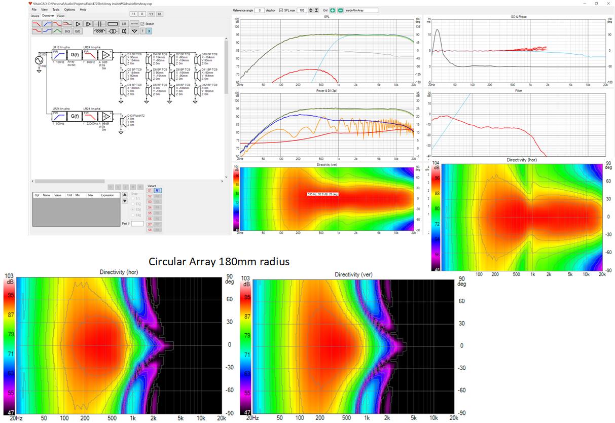
taking the hint, I created model for a circle of BP TC9s with 180 mm radius and simulated that with the fluid472 waveguide. this is what we might get if we did the MEH thing and cancelled the reflection of the mids from the CD's phase plug.
Attachments

They are within the horn, I believe you'll find it mentioned in the Unity patent.
It still is conforming to the Synergy concept i.m.h.o. (at least in spirit) Just not used similar to what Danley does.
He has other priorities, but mentions how and where the drivers should go for a certain frequency reach. I believe you're doing just that.
It still is conforming to the Synergy concept i.m.h.o. (at least in spirit) Just not used similar to what Danley does.
He has other priorities, but mentions how and where the drivers should go for a certain frequency reach. I believe you're doing just that.
Last edited:
the spirit of Synergy is to create a virtual point source from multiple drivers.
the spirit of this is to place the ring of drivers far enough out from the apex so that they don't combine with it to form a virtual point source and instead act as separate drivers, or a single ring radiator, extending pattern control to lower frequencies.
the spirit of this is to place the ring of drivers far enough out from the apex so that they don't combine with it to form a virtual point source and instead act as separate drivers, or a single ring radiator, extending pattern control to lower frequencies.
If one extends the pattern control of a horn, in the full sense, while doing this as entries into the horn, how is this different from a Unity/Synergy and how can it not be seen as a virtual point source if one does just that?
the spirit of Synergy is to create a virtual point source from multiple drivers.
the spirit of this is to place the ring of drivers far enough out from the apex so that they don't combine with it to form a virtual point source and instead act as separate drivers, or a single ring radiator, extending pattern control to lower frequencies.
Hi Jack,
but don't you have to blend the ring with the driver at the apex?
Or have you been working without any type driver at the apex....that would be truly radical !!.....sorry for not have fully followed along.
Otherwise, if there is a driver at the apex, i think i'm asking the same thing wesayso is...that being, isn't a ring array speaker essentially a flattened synergy without a horn ?
Vituix will allow you to model things that are not realisable and because it is good at interpolating you can still get realistic looking results.
It might work just as nc535 has modelled but at that distance the entries will be in the horn and the effect that has on the directivity of the woofers and the directivity and diffraction from the horn is not accounted for.
What I do quite like is the vertical pattern and if that could perhaps be mirrored more on the horizontal that could be good.
The power response dip vs in room response variation is an interesting point too.
I've had a couple of lightbulbs come on due to reading this Genelec paper, nothing concrete yet but I see possibilities there.
https://downloads.ctfassets.net/4zjnzn055a4v/4fBjWIVqybNHuuzz7EPb9l/e75b60ca279e0843e7da0ebc448eb13d/AES_142_-_The_Acoustic_Design_of_Minimum_Diffraction_Coaxial_Loudspeakers_with_Integrated_Waveguides.pdf
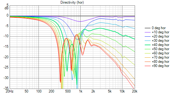
if drivers (mids+CD) are within 1/4 lambda of each other at crossover, then there is no angle from which the crossed over ensemble can be viewed at which destructive combination will occur.
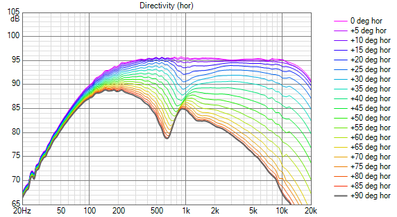
if the ring isn't combining with the CD into a point source then if we measure its FR from an extreme off axis angle, we should see FR ripple from drivers on opposite sides of the ring combing with each other, like looking at a line array from the end.
Here is horizontal line chart for wg+ring. Its flat on axis and progressively unflat as you go further off axis. I think that the valley below 1 khz that deepens as we go off axis is due to the ring combing with itself
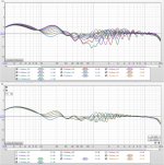
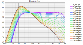
Here is the wg only, assumed to be synergized so plays from 100 Hz up. Don't ask me to explain response below 400 Hz, but above it, response is not exactly flat but doesn't have that ripple we saw in prior chart for all off axis angles. After equalizing the CD, the only change in FR with angle for the synergy should be due to the horn shape.

if the ring isn't combining with the CD into a point source then if we measure its FR from an extreme off axis angle, we should see FR ripple from drivers on opposite sides of the ring combing with each other, like looking at a line array from the end.
Here is horizontal line chart for wg+ring. Its flat on axis and progressively unflat as you go further off axis. I think that the valley below 1 khz that deepens as we go off axis is due to the ring combing with itself
Here is the wg only, assumed to be synergized so plays from 100 Hz up. Don't ask me to explain response below 400 Hz, but above it, response is not exactly flat but doesn't have that ripple we saw in prior chart for all off axis angles. After equalizing the CD, the only change in FR with angle for the synergy should be due to the horn shape.
Attachments

Hi Jack,
but don't you have to blend the ring with the driver at the apex?
Or have you been working without any type driver at the apex....that would be truly radical !!.....sorry for not have fully followed along.
Otherwise, if there is a driver at the apex, i think i'm asking the same thing wesayso is...that being, isn't a ring array speaker essentially a flattened synergy without a horn ?
blend? well there is definitely a crossover between the HF1440 CD at apex and these mids out near rim.
its like a synergy but it violates the drivers within 1/4 lambda of each other rule and therefore it doesn't synergize, doesn't become a virtual point source
So the reason it isn't a Synergy/Unity is because the ring of drivers is still outside quarter wavelength of the crossover frequency. Ok, got it.
Edit: you beat me to it, confirming it.
Edit: you beat me to it, confirming it.
It is due to using normalized data and not measured data. There is a tipping point where off axis goes up the further you go.Don't ask me to explain response below 400 Hz,
Vituix will allow you to model things that are not realisable and because it is good at interpolating you can still get realistic looking results.
It might work just as nc535 has modelled but at that distance the entries will be in the horn and the effect that has on the directivity of the woofers and the directivity and diffraction from the horn is not accounted for.
What I do quite like is the vertical pattern and if that could perhaps be mirrored more on the horizontal that could be good.
The power response dip vs in room response variation is an interesting point too.
I've had a couple of lightbulbs come on due to reading this Genelec paper, nothing concrete yet but I see possibilities there.
https://downloads.ctfassets.net/4zjnzn055a4v/4fBjWIVqybNHuuzz7EPb9l/e75b60ca279e0843e7da0ebc448eb13d/AES_142_-_The_Acoustic_Design_of_Minimum_Diffraction_Coaxial_Loudspeakers_with_Integrated_Waveguides.pdf
My major purpose in modelling was to see if 180 mm was the correct radius for the ring in that waveguide. I said "this is what we might get if..."
If you create the abec model, we can get a good idea how close we could come to that ideal in reality. I would not want to have to go through the abec model multiple times optimizing the ring diameter. It might be a good idea to try 190 and 200 mm because the further out we put the ports, the less harm they will do...so we should find the limit.
as well find how small we can make the holes from a bandpass response and particle velocity point of view. I modelled 4:1 compression; can likely go 8:1;
It is indeed curious that H and V maps aren't identical absent any boundaries
so there is lots to do once we are convinced we have proof of concept.
I'm just now once again realizing how much a normalized polar map can hide. These un-normalized charts are more informative.
It is due to using normalized data and not measured data. There is a tipping point where off axis goes up the further you go.
thanks
- Home
- Loudspeakers
- Full Range
- Full range line array for wall or corner placement