I did get the text, I guess I'm missing the visualization 😀.
While I'm reading your posts, I'm just in deep thought how to make that array more seamless from top to bottom. There must be a way to get it to behave even better. But at 500 to 2 KHz, it isn't an array.
Could a vertical extension of the midranges (the TC drivers) help to counter that? You've got a circle of them right now. What if you covered more ground at top and bottom in the middle section (even more drivers) to steer the beam there.
that is what I've been thing about also except more wondering why it has that particular misbehavior in that range
Instead of adding more drivers outside the rim, why not overlap the rim drivers with the CD instead of a hard cross at 800 Hz? that could have much the same effect although I'm not sure how high the overlap could go
I know that is what I did you get the straightest beam I could get. I use a lot of overlap within that vertical range to do the beam steering. That made it quite indifferent from the room variables. Except of course a side wall, which sure needs help.
Its just a few clicks to create the overlap. 1100 looks to be as far as I should push it, excessive narrowing beyond but maybe I should try anyway
the character of the FR hasn't changed but I've reduced the envelope to ~ +/-2.5 db for +/- 200mm around eq height. thanks for the suggestion!
I'm not including wall reflections any longer; I think its a good assumption walls will be treated appropriately. Due to controlled directivity, minimal treatment is needed.
I'm also not going to equalize the room response but instead eq the direct beam flat and then look at the room responses. In practice there will be some room eq and voicing.
Attachments
The only afterthought I kept in mind was keeping a "decent curve" at standing height (1m70 in my case) but I did allow for wiggles. etc there. As long as the total curve did look somewhat straight (even tilted down, rather than up).
I only accepted what was better in all positions I could think of, the key largely was uniformity over a wide vertical stretch. Which is what we see in the fractal arrays as well. That does a good job of limiting floor and ceiling. Like you, I think it's much easier to do something about walls etc. In fact, I counted on that.
Damping panels can be made to target deviations in in-room response. Ambient channels can be used to make up for what you stole of the room. At least, that has been my way of countering the room.
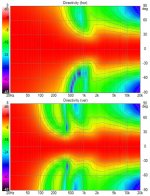
The waist shape seen at 500-2 KHz horizontally would concern me. I would lessen the power of the drivers to the side of the horn, or let go of them completely if possible.
In my book the horizontal would be allowed to gradually grow wider, but not have any waist banding like that. As that surely would bite you in in-room response.
In my book the horizontal would be allowed to gradually grow wider, but not have any waist banding like that. As that surely would bite you in in-room response.
Now you are talking about more than a few clicks to create the overlap. Now its equal weighting. Need to adjust it to tailor the directivity...
I did want to and I went to the extent of using RePhase to create an overlap XO. I didn't think it would reduce the residual ground reflection FR ripple but I wanted to see if I could do it. I was only a little bit surprised when widening the vertical window in that region actually made the residual worse.
That reminded me what I've known for some time - 60 degree (+/-30) vertical directivity is too wide! At typical listening distances of 3-4m the ground reflection is right in the seated listener's face.

Its clear that the narrowing of vertical window below the waveguide cutoff is exactly what is needed to eliminate/reduce the ground interference. I would say carpeting is called for to counteract it at the high end.
That reminded me what I've known for some time - 60 degree (+/-30) vertical directivity is too wide! At typical listening distances of 3-4m the ground reflection is right in the seated listener's face.
Its clear that the narrowing of vertical window below the waveguide cutoff is exactly what is needed to eliminate/reduce the ground interference. I would say carpeting is called for to counteract it at the high end.
Attachments
Why does this concern you? (other than it not being totally ideal)The waist shape seen at 500-2 KHz horizontally would concern me.
Some good news and some bad news, sour grapes and wine
when I started the slot version of the clock face I asked Kimmosto to clarify rotation in Vituix so I could get that part of it right. When he didn't answer right away, I went ahead with my best guess which turns out not to have been very good. I should have known Vituix doesn't support rotation of a driver around the Z axis. So my slot simulations need to be redone with corrected models. The good news is those models can be done in ABEC and perhaps thats the motivation I need to get up the learning curve. Modelling a rectangular diaphragm on a rectangular baffle is a pretty simple place to start.
when I started the slot version of the clock face I asked Kimmosto to clarify rotation in Vituix so I could get that part of it right. When he didn't answer right away, I went ahead with my best guess which turns out not to have been very good. I should have known Vituix doesn't support rotation of a driver around the Z axis. So my slot simulations need to be redone with corrected models. The good news is those models can be done in ABEC and perhaps thats the motivation I need to get up the learning curve. Modelling a rectangular diaphragm on a rectangular baffle is a pretty simple place to start.
aside to fluid's question and my prior post:
the waveguide is axisymmetric so widening it in the neck affects both H and V
the waveguide is axisymmetric so widening it in the neck affects both H and V
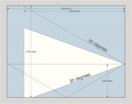
for the clock face the angles are multiples of 30 degrees. obvious symmetry
The simple case is just that 10mm by 60mm or so slot on a baffle
The ultimate case is all 12 of them on a baffle with the waveguide, active diaphragms behind all the slots, waveguide mouth closed off, baffle having a thickness...
The simple case is just that 10mm by 60mm or so slot on a baffle
The ultimate case is all 12 of them on a baffle with the waveguide, active diaphragms behind all the slots, waveguide mouth closed off, baffle having a thickness...
Why does this concern you? (other than it not being totally ideal)
Because it would light up the room irregularly. It would be very hard to make up for that. Horizontally is the main concern in what I do consider an important frequency band.
We do have our ears placed horizontally, plus we get cross talk 'contamination' right in that area (leaving you with dips around that frequency) and Id rather have a bit wider dispersion around ~2 KHz than more narrow.
Within crosstalk we get more energy at 3 KHz, that's right where this pattern starts to grow wider.
Both in horizontal and vertical direction.
I wouldn't even put it as being not totally ideal, it definitely wouldn't be what I want. I'd rather have something like that happening outside of the vocal band. But to avoid it completely would obviously be even better.
Vertically it wouldn't be ideal either, but I think it would be perceived different. but this design isn't completely ideal in that direction either, so it could further enforce the perceived difference between direct/indirect sound.
We can steer a lot with room treatment, but i don't think it will or can cure everything. I'd imagine the room would sound "off". Hard to tune.
On axis direct sound would simply not agree with the later arriving room response. That is something that I've been trying to target within my room, the damping panels have been targeted to keep it balanced similarly. Not using a CD solution doesn't mean you can't get that balance a bit better, within reason.
Even if it is sloped, as long as it is gradually happening I'd imagine it would sound better, easier to get a satisfying tonal balance.
That is why I even expect horns like the JMLC type to be able to create a pleasing tonal balance, as the bandwidth grows gradually and smooth. No sudden changes. Least of all in the vocal area.
Even though it would make for a small sweet spot, not a sweet area.
Just my thoughts on this, feel free to see it differently.
Attachments

Last edited:
Here is where the sour grapes come in 🙂
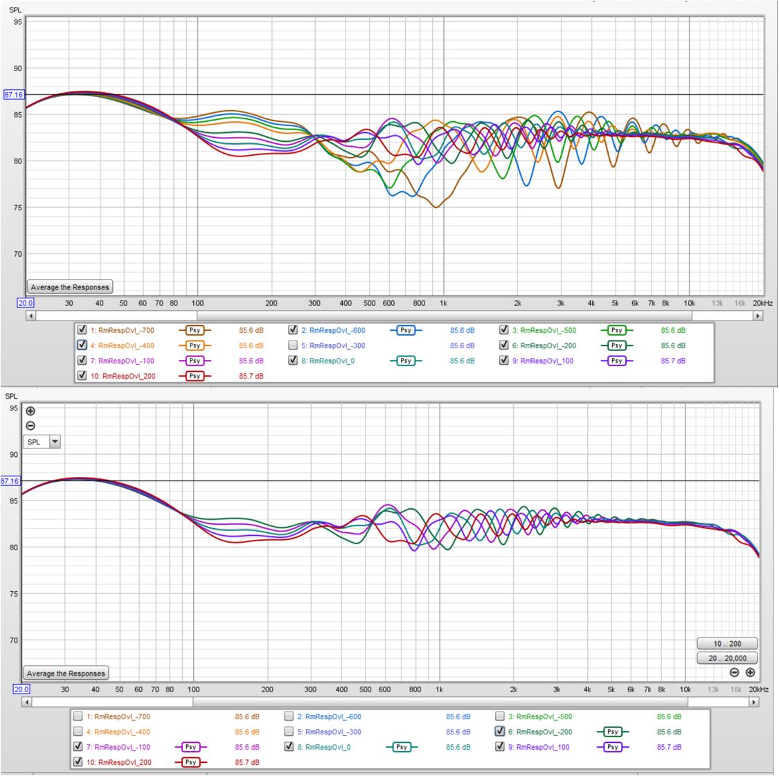
Knowing my slot models weren't any good, I went back to the original clockface waveguide surround with the full cones of the TC9s exposed. Realizing that narrowing of the vertical could be a good thing, I revised the XO with asymmetric slopes on the wg-tc9 XO at 600 hz - 12 db/octave for the TC9 low pass and 24 db/octave for the wg highpass,
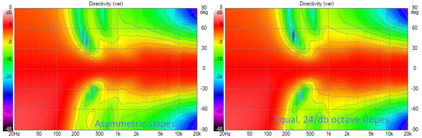
Its not a huge change but the improvement in un-EQed room response is apparent. (Direct, axial response was eqed flat
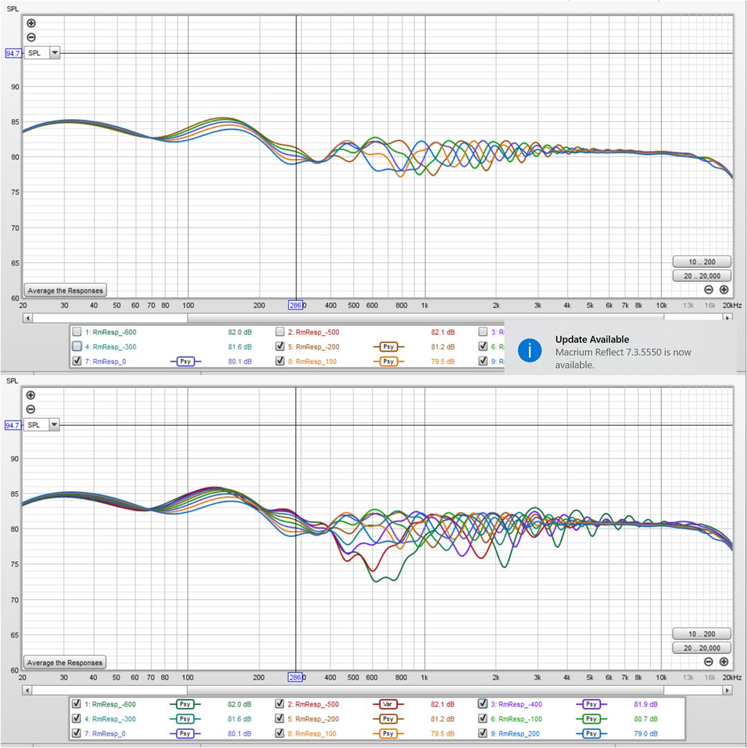
The residual variation for +/- 200mm around seated listening position (top graph) is down to +/- 2db!
As a reminder, this model has a TD15 at floor level overlapping the TC9s up to 400 Hz.
Knowing my slot models weren't any good, I went back to the original clockface waveguide surround with the full cones of the TC9s exposed. Realizing that narrowing of the vertical could be a good thing, I revised the XO with asymmetric slopes on the wg-tc9 XO at 600 hz - 12 db/octave for the TC9 low pass and 24 db/octave for the wg highpass,
Its not a huge change but the improvement in un-EQed room response is apparent. (Direct, axial response was eqed flat
The residual variation for +/- 200mm around seated listening position (top graph) is down to +/- 2db!
As a reminder, this model has a TD15 at floor level overlapping the TC9s up to 400 Hz.
Attachments

Have a look here for some information from DonVK and a test script, in case it is hard to see it is the semicolon separator between terms that is causing the issue
I found and fixed the semicolon issue on my own.
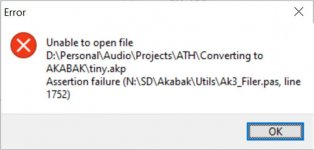
Today I tried running Don's tiny.akp and got an error message on the load. but it did load. but I don't know what to do in the program after I've pressed return, so to speak
I don't recognize the path in it or anything like it where I keep akabak. frustration
Attachments
I don't see it much differently, except I think the change in directivity is quite smooth in the horizontal and over a range of 2-3dB and I don't think that it would cause an off axis response that is unworkable. This could no doubt be made better with changes to the waveguide as it was in no way optimized for this use but making a waveguide with a high level of H to V asymmetry to match a +/-20 vertical window makes other compromises that I wouldn't want. I'm a little surprised than an axisymmetric guide blends this well.Just my thoughts on this, feel free to see it differently.
As a system with more dynamic potential than a fractal of straight expanding array but with some of their directivity traits I find it quite attractive.
for the clock face the angles are multiples of 30 degrees. obvious symmetry
The simple case is just that 10mm by 60mm or so slot on a baffle
That will be easy enough and there will be no real need for symmetry in the simple case, I would think you would need each one as a separate response to have Vituix deal with it correctly.
This could be progressed to get it to that stage but the waveguide would probably have to be remeshed at a lower resolution to save time.The ultimate case is all 12 of them on a baffle with the waveguide, active diaphragms behind all the slots, waveguide mouth closed off, baffle having a thickness...
Symmetry is usually x y z or xy xz etc. Half quarter or circular.with symmetry can you do just a 30 degree pie slice?
Do you mean the mesh and parameters load but you don't know what the next step is?Today I tried running Don's tiny.akp and got an error message on the load. but it did load. but I don't know what to do in the program after I've pressed return, so to speak
I wouldn't worry too much about it if it loaded the script seems like an internal Akabak file parsing error.I don't recognize the path in it or anything like it where I keep akabak. frustration
What you could do is create a blank project with the subdomains driver and observations laid out like in mabat's scripts then to change waveguides you could just import the new mesh as all the parts in it are tagged the same.
Did you watch the videos I linked before they should be some use in working out what you can do with it.
- Home
- Loudspeakers
- Full Range
- Full range line array for wall or corner placement