thanks. Drivers are easy to find. Drivers with detailed measurements available before purchase are more difficult.
I talked myself into looking at helmholtz resonators.
I found this calculator
Helmholtz Resonator
These things are often used in large scale as bass traps. Scaled down, the block diagram looks like a bandpass cabinet where the cabinet volume is the air trapped between the driver cone and the horn wall
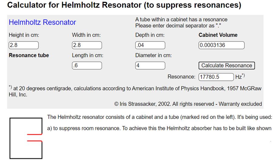
Its difficult to tune the resonator out of band. The closest I came is shown in the picture above. I set the volume assuming a volume plug is implemented on the horn wall to minimize air volume. I assumed a volume of driver SD times 2x linear Xmax. I assumed a tapered/frustrumed port with an effective length of .6 cm, and then adjusted the diameter. I was surprised that increasing the diameter increased the resonant frequency. I ended up with a diameter of 4 cm and resonance at ~18kHz This is not the direction I wanted to go!
The next try was to get the resonance below the passband. I used cabinet area representative of TC9 instead of DMA45 and trapped a generous amount of air, set the dia. to 1cm and tuned the length to a resonance of 377Hz, just under 400 Hz XO (probably should have gone lower)
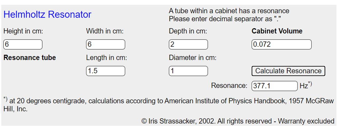
This represents a TC9 stood 2cm off the back of the horn wall with a 1cm diameter tube sticking back 1.5 cm into the trapped air volume. This is at least feasible. (but that doesn't mean its worth doing)
I found this calculator
Helmholtz Resonator
These things are often used in large scale as bass traps. Scaled down, the block diagram looks like a bandpass cabinet where the cabinet volume is the air trapped between the driver cone and the horn wall
Its difficult to tune the resonator out of band. The closest I came is shown in the picture above. I set the volume assuming a volume plug is implemented on the horn wall to minimize air volume. I assumed a volume of driver SD times 2x linear Xmax. I assumed a tapered/frustrumed port with an effective length of .6 cm, and then adjusted the diameter. I was surprised that increasing the diameter increased the resonant frequency. I ended up with a diameter of 4 cm and resonance at ~18kHz This is not the direction I wanted to go!
The next try was to get the resonance below the passband. I used cabinet area representative of TC9 instead of DMA45 and trapped a generous amount of air, set the dia. to 1cm and tuned the length to a resonance of 377Hz, just under 400 Hz XO (probably should have gone lower)
This represents a TC9 stood 2cm off the back of the horn wall with a 1cm diameter tube sticking back 1.5 cm into the trapped air volume. This is at least feasible. (but that doesn't mean its worth doing)
Attachments

Last edited:
thanks. Drivers are easy to find. Drivers with detailed measurements available before purchase are more difficult.
Ok, detailed measurements was in the attachment, granted K+T is not my favourite! Other than that, I don't find measurements difficult to find with Audioexpress, Hifitest.de, HobbyHifi and a plethora of European sites...
Anyway, following with interest!
Peter
I think you took me wrong, my fault for not being clearer. I followed the link to the article/review of the driver and was pleased to see all that detail. OTOH, 30 euros for the monacor vs $8 for the dayton is disappointing.
but I don't think the helmholtz resonance is what does the main damage. The resonance could cause a dip at a single frequency. Diffraction of the primary beam off the edge of the port hole could affect areas of the spectrum in which the hole dimension is a significant fraction of a wavelength.
Therefore I think the strategy should be to shrink the port dimensions on the theory that they will be invisible to frequencies whose wavelength is a fraction of those dimensions.
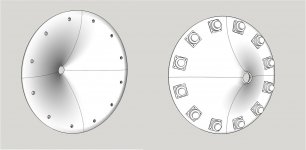
Now a 1 cm2 port area for 12 drivers looks sufficient. This could be a slot 50 cm long by 20 cm wide with the long edge tangent to the mounting circle.
I'm now doing some modelling that indicates that the mids can be moved out to a radius of 210 cm. This will put the mids closer to the rim of the waveguide where they will find a flatter mounting surface. Since this is out on the roundover of the waveguide, there is reason to hope that the high frequencies susceptible to damage by the slots will fly right over them without being affected
Therefore I think the strategy should be to shrink the port dimensions on the theory that they will be invisible to frequencies whose wavelength is a fraction of those dimensions.
Now a 1 cm2 port area for 12 drivers looks sufficient. This could be a slot 50 cm long by 20 cm wide with the long edge tangent to the mounting circle.
I'm now doing some modelling that indicates that the mids can be moved out to a radius of 210 cm. This will put the mids closer to the rim of the waveguide where they will find a flatter mounting surface. Since this is out on the roundover of the waveguide, there is reason to hope that the high frequencies susceptible to damage by the slots will fly right over them without being affected
whoops those slot dimensions are wrong and not just by factor mm vs cm
A tc9 slot could by 75mm by 13mm
A dma45 slot could be 40 mm by 25 mm
A tc9 slot could by 75mm by 13mm
A dma45 slot could be 40 mm by 25 mm
nc535,
when you've got a bunch of Helmholtz resonators, it's a good idea to check the dimensional tolerances needed to keep the responses well enough matched.
I got caught out with an array of four ported mids (Helmholtz low-pass filters). They all had slightly different responses, both resonant frequency and Q. I was driving them from one amplifier, so was stuck with a compromise. On later arrays I brought the mids back out front (and suffer a dip in off-axis response near 1-2kHz as a result - something that doesn't seem to be a disaster in my room - the opposite sounds worse to me).
You'll make the ports more precisely than my unskilled woodwork, I'm sure, but it's still worth checking the required tolerance (e.g. by mockup).
In a usual MEH application, the differences among the mid response would average out which may be why this is not a commonly seen problem. An H-K based array is less tolerant, I believe.
Ken
ps. I really like what you are doing - I've not had time recently to read through every post in detail, but several of your results are very encouraging.
nc535,
when you've got a bunch of Helmholtz resonators, it's a good idea to check the dimensional tolerances needed to keep the responses well enough matched.
I got caught out with an array of four ported mids (Helmholtz low-pass filters). They all had slightly different responses, both resonant frequency and Q. I was driving them from one amplifier, so was stuck with a compromise. On later arrays I brought the mids back out front (and suffer a dip in off-axis response near 1-2kHz as a result - something that doesn't seem to be a disaster in my room - the opposite sounds worse to me).
You'll make the ports more precisely than my unskilled woodwork, I'm sure, but it's still worth checking the required tolerance (e.g. by mockup).
In a usual MEH application, the differences among the mid response would average out which may be why this is not a commonly seen problem. An H-K based array is less tolerant, I believe.
Ken
ps. I really like what you are doing - I've not had time recently to read through every post in detail, but several of your results are very encouraging.
Thanks. I'm definitely concerned about the HH resonance. I haven't been able to quantify the effect yet. If I can get to ABEC we shall see.
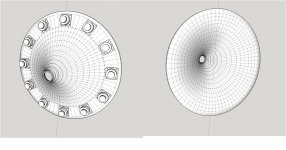
If it made mounting or positioning easier I have a slightly squashed rectangular version of the HF1440 round guide.
I'm not saying its easier (I've been feeling your pain 🙂)but so far I prefer the round one. I've brought it into Sketchup, extracted the profile and re-spun to create a wg that is easier to do CAD on. I thickened it, add flat back edge for recessed mounting in baffle, added a flat angled surface for mounting the DMA45s, and got them positioned. Next step will be "drilling" the port holes through the thickened waveguide.
The extracted profile is only piecewise continuous, thus the "construction lines.
I will try to mesh it after I get the holes in but that will be a first for me...
Attachments
Personally I'm not that keen on sketch-up having seen (a lot of) data created with it on several occasions (at work).
I an recommend using the free Fusion360 tool from Autodesk (free for the hobbyist, for non commercial work): Fusion 360 for Personal Use | Fusion 360 | Autodesk
I an recommend using the free Fusion360 tool from Autodesk (free for the hobbyist, for non commercial work): Fusion 360 for Personal Use | Fusion 360 | Autodesk
the most valuable feature of Sketchup to me is that I've become proficient with it. Its very good for woodworking but its not the tool of choice for 3D modelling. Somehow I'm ususally able to get the job done. Starting up the same learning curve in Fusion would be a setback.
Fusion 360 is much easier to learn than SketchUp - at least for myself. I was at zero point with both. I ended up with F360 and use it for all my 3D print models. Maybe it is because I worked a lot with2D AutoCAD in the past.

If you mesh it like that I can almost guarantee it won't work very well.
This is what I just wrote and it applies here too,
One tip if you have made the horn contour in Ath is to export it from ABEC as an STL file, import that into CAD, cut it on one of the profile lines with a plane created from on the vertices. Then create a polyline out the edge and use that to cut the solid waveguide. When you export both you can combine them back together with the vertices aligned as gmsh will mesh to the cut vertices on the solid waveguide. That way you have a higher density from the driver to the cut based on mabat's geocode which is much better than anything gmsh can do on its own. Then you can use a lower density on the outer parts. This took my simulation from 5 hours plus to 1 hour 40 with exactly the same result.
You only need the solid or surface just before the ports, in an infinite baffle ABEC doesn't care if your driver cone is exposed behind it as long as there is a closed path from the front of it to the port and there is an interface between the inside and outside to couple the subdomains.
I think you are telling me that I need to cut the wg into a mouth section and a throat section so I can do the throat at higher resolution and you are telling me how to do it cleanly. The process may be different in Sketchup (Its solids have hidden geometry that you can unhide and use to make clean cuts.)but I get the idea and will work towards that. In the meantime I'm happy that Sketchup is only putting up token resistance to my efforts.
I went back to HR to compare my CAD of the bandpass to the simulation and to check the simulation itself. In doing that I found that 0.5 cm2 port area was sufficient for 106 db total SPL in Vituix. So I'm going back through the CAD loop to implement the smaller hole and the shallow bandpass chamber, really just enough to accomodate the half round suspension + 1mm

The new BP chamber has a volume of 8 cm2 x .3 cm deep and a port dia of 8mm by 0.65mm long. This has a helmholtz resonance of 2223 Hz. Looking at port diameter in relation to the full waveguide, its hard to believe that either the hole or the resonance will have a great effect; but we shall see.
the holes are 100 mm apart and the wavelength of 2222 Hz is ~155 mm.
the more critical question to be answered in simulation is how big the reflection from the CD's phase plug is and whether its realistic to try to cancel it. This means I will need to mesh and simulate two different models: one in which the CD drives and one in which the mids drive.
I went back to HR to compare my CAD of the bandpass to the simulation and to check the simulation itself. In doing that I found that 0.5 cm2 port area was sufficient for 106 db total SPL in Vituix. So I'm going back through the CAD loop to implement the smaller hole and the shallow bandpass chamber, really just enough to accomodate the half round suspension + 1mm
The new BP chamber has a volume of 8 cm2 x .3 cm deep and a port dia of 8mm by 0.65mm long. This has a helmholtz resonance of 2223 Hz. Looking at port diameter in relation to the full waveguide, its hard to believe that either the hole or the resonance will have a great effect; but we shall see.
the holes are 100 mm apart and the wavelength of 2222 Hz is ~155 mm.
the more critical question to be answered in simulation is how big the reflection from the CD's phase plug is and whether its realistic to try to cancel it. This means I will need to mesh and simulate two different models: one in which the CD drives and one in which the mids drive.
Basically that is what I am suggesting, the meshes generated from Ath get progressively coarser as they move away from the throat and this really helps to keep the simulation time down but still be accurate.
The physical volume of the space occupied by the simulation plays a large part in how long it will take. This is quite a big waveguide and even with 1/4 symmetry and an infinite baffle it will take anywhere from 1 to 5 hours plus to run. It is disappointing after waiting 5 hours to find that you stuffed something and the results are garbage.
At 4mm mesh edges an 8mm hole will look like a square, meshing the entire outer edge at 2mm will produce a huge number of elements and for me gmesh is not that good at putting the triangles where they are needed on these sort of varying surfaces if you let the density be variable.
The other thing to think about when using CAD to make ABEC models is that you only need the surfaces and often it is easier to model only the surfaces you need than it is to try and bring in a full solid.
Trying to make a practical solid model and then turning it into the required surfaces afterwards is a lot more difficult and I eventually stopped trying.
Your last image attachment has vanished again.
Funny, I see all my recent images. They are all linked via preview attachment and copy/paste image address method. That last image was a composite of 3 screenshots with the lower right section blank
I hear you re sim time, mesh resolution, and solid practical model. Do I just keep working on the quadrant model or do I draw it all out so the tools find and exploit the symmetry?
I hear you re sim time, mesh resolution, and solid practical model. Do I just keep working on the quadrant model or do I draw it all out so the tools find and exploit the symmetry?
- Home
- Loudspeakers
- Full Range
- Full range line array for wall or corner placement