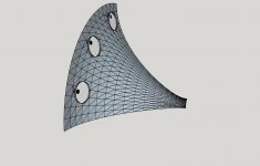
I usually make the whole thing in one as it is easier to patch a complete hole (than it is a quarter of one) if that is needed as a surface or interface, then I split the bodies with the y and x planes and hide all the stuff I don't need before exporting to step. I keep the upper right corner as it fits with what Ath does.
For this you only need to model the surfaces that the sound can travel along, the interior of the cone surround chamber and port. The magnet, chassis, back of the waveguide are not needed if you mount it in an infinite baffle.
For this you only need to model the surfaces that the sound can travel along, the interior of the cone surround chamber and port. The magnet, chassis, back of the waveguide are not needed if you mount it in an infinite baffle.

The smiley is missing. I'm going to get through the ath demo then find an abec project script to hack
I have attached a modified version of the original ABEC project. If you add your STL to the meshes by right clicking on mesh files in the project tree and selecting add mesh, give it the alias M2 as that is what I have used. Makes sure your STL is scaled in mm or you need to adjust the mesh file properties in solving.txt otherwise everything will seem wrong or disappear.
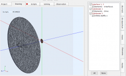
If you click on the elements tab you can see what is included in the model and turn on or off the visibility of different elements.
I don't know that the stl will work very well, if you zoom in on the ports, how do the big triangles join the small ones in the port?
If you click on the elements tab you can see what is included in the model and turn on or off the visibility of different elements.
I don't know that the stl will work very well, if you zoom in on the ports, how do the big triangles join the small ones in the port?
Attachments
Thanks, I will try that first thing tomorrow
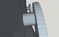
let me know if you think I should add or subtract detail around the ports, I can reduce the number of triangles needed for the rear chambers very easily. I would hope not to have to change the holes through the horn wall...
let me know if you think I should add or subtract detail around the ports, I can reduce the number of triangles needed for the rear chambers very easily. I would hope not to have to change the holes through the horn wall...
Attachments
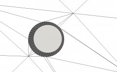
I don't think that stl will work that well but it is hard to say without trying. If it was me I wouldn't simulate it until I got the vertices better aligned. You can see in the close up port shot that the triangles don't match.
I can see the desire to use the same program to CAD and mesh but I haven't tried to do that, controlling the edge lengths and number of elements is tricky at the best of times.
I can see the desire to use the same program to CAD and mesh but I haven't tried to do that, controlling the edge lengths and number of elements is tricky at the best of times.
I converted it to msh in gmsh, read it in, wrote it out for what that is worth. Then I renamed it to HF1440.msh and put it in the directory unzipped from what you gave me.
The solver.txt has two MeshFileAlias's M1 and M2. It finds M1 as the the HF1440 and errors on M2
M1 is an interface and drive element, would that be a 1.4" disk at the throat?
The solver.txt has two MeshFileAlias's M1 and M2. It finds M1 as the the HF1440 and errors on M2
M1 is an interface and drive element, would that be a 1.4" disk at the throat?
just now looking at your HF1440.msh and seeing that I need to close the throat and mouth with surfaces and rotate to get the orientation right.
...having fun now....
one of the tools in the path is scaling it wrong, working on that
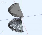
abec didn't join the quadrants correctly,

any idea what is wrong? I'm thinking orienation of my quad. I sliced out upper right corner with horn mouth facing me in "standard camera view: front"
I ran ABEC anyway through to conclusion which was message saying result files not created due to no release code. Begging Joerg for release code
one of the tools in the path is scaling it wrong, working on that
abec didn't join the quadrants correctly,
any idea what is wrong? I'm thinking orienation of my quad. I sliced out upper right corner with horn mouth facing me in "standard camera view: front"
I ran ABEC anyway through to conclusion which was message saying result files not created due to no release code. Begging Joerg for release code
Attachments
You basically undid everything I modified to make it work together for you 😉 The point was to leave the original interface and driver meshes as M1 and import your waveguide as M2 so you could see how they fit together.I converted it to msh in gmsh, read it in, wrote it out for what that is worth. Then I renamed it to HF1440.msh and put it in the directory unzipped from what you gave me.
The solver.txt has two MeshFileAlias's M1 and M2. It finds M1 as the the HF1440 and errors on M2
M1 is an interface and drive element, would that be a 1.4" disk at the throat?
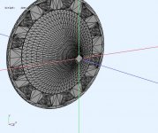
In Fusion Y is up down (top to bottom) X is left to right and Z is in out (front to back), if sketchup doesn't work like that then I suggest you rotate your model so it does, I find this the easiest way to visualize it and it matches Ath script output and my own.ran original HF1440 and see ABEC orientation of axes, which is different from Sketchup's, assuming color is signficant
matched the orientation and got the right picture
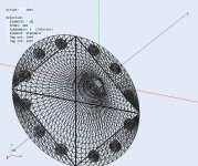
I don't think you have it right it looks like the grey is on the back side of the waveguide which means the normals are reversed.
This is deep water to be starting out in, if you want to upload the msh here I can look and see what is happening.
darn - didn't get an alert/email on your post, just found it this AM
I ended up doing that - importing my stl as M2 once I saw how easy it was
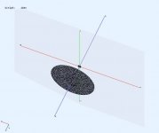
what confuses the drawing is the closure of the mouth which obscures the view from the front
Sketchup in "camera standard view - front" has blue axis up, red to the right, and green out of the plane to the viewer. Red=X, Blue=Y, Green= Z. This is inferred; there is no such setting or definition in Sketchup so I rotated the drawing in sketchup before exporting stl to match ABEC3 (X=red, Y=Grn, Z=blue) or thought I did, looks like I have Z reversed.
I'm dead-ended with an ABEC3 key; but I do have a key for AKABAK so I'm now trying to get orientation right in AKABAK. but I can't get AKABAK to show me the same drawing as ABEC3 and I can't find the place to set Horizonal polar plane to ZX per DonVK's post...
I will flip the Z axis and try again; hopefully abec and akp work the same
I ended up doing that - importing my stl as M2 once I saw how easy it was
what confuses the drawing is the closure of the mouth which obscures the view from the front
Sketchup in "camera standard view - front" has blue axis up, red to the right, and green out of the plane to the viewer. Red=X, Blue=Y, Green= Z. This is inferred; there is no such setting or definition in Sketchup so I rotated the drawing in sketchup before exporting stl to match ABEC3 (X=red, Y=Grn, Z=blue) or thought I did, looks like I have Z reversed.
I'm dead-ended with an ABEC3 key; but I do have a key for AKABAK so I'm now trying to get orientation right in AKABAK. but I can't get AKABAK to show me the same drawing as ABEC3 and I can't find the place to set Horizonal polar plane to ZX per DonVK's post...
I will flip the Z axis and try again; hopefully abec and akp work the same
- Home
- Loudspeakers
- Full Range
- Full range line array for wall or corner placement