I did not mean to imply it was a waste of time and it was more in response the previous synergy/ring comments.My major purpose in modelling was to see if 180 mm was the correct radius for the ring in that waveguide. I said "this is what we might get if..."
I have been working on it but I have been concentrating on using a 5" driver, as I have those. I need to put them where they fit not necessarily exactly where I want. It is not simple (for me) to model it all and have it meet up correctly. Once I have that worked out it will not be so difficult to make it representative of a TC9.If you create the abec model, we can get a good idea how close we could come to that ideal in reality. I would not want to have to go through the abec model multiple times optimizing the ring diameter. It might be a good idea to try 190 and 200 mm because the further out we put the ports, the less harm they will do...so we should find the limit.
That will be useful I have usually assumed 10:1 or less.as well find how small we can make the holes from a bandpass response and particle velocity point of view. I modelled 4:1 compression; can likely go 8:1;
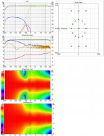
It isn't the polar map per see but the scale the Vituix represents that can be flattering 🙂I'm just now once again realizing how much a normalized polar map can hide. These un-normalized charts are more informative.
I have been somewhat distracted by the ideas of slot ports behind the baffle a la genelec with a flat baffle given that the H to V ratio can be altered to suit what is needed rather that being stuck with the pattern a ring gives. This would be much easier to design but more time consuming to simulate.
Getting the ring small enough and the directivity of the waveguide right to support a low enough crossover was what made me set aside the idea when it came up in Ken's thread. The Genelec Coaxial driver is a solution to that issue but then it becomes SPL limited and not diyable as far as I can see.
My feeling about TC9s is that they are low enough cost that they question of how many is not so important. But its more important if using 5" drivers, as 12 might not fit. Its also good to reduce back chamber volume requirements.
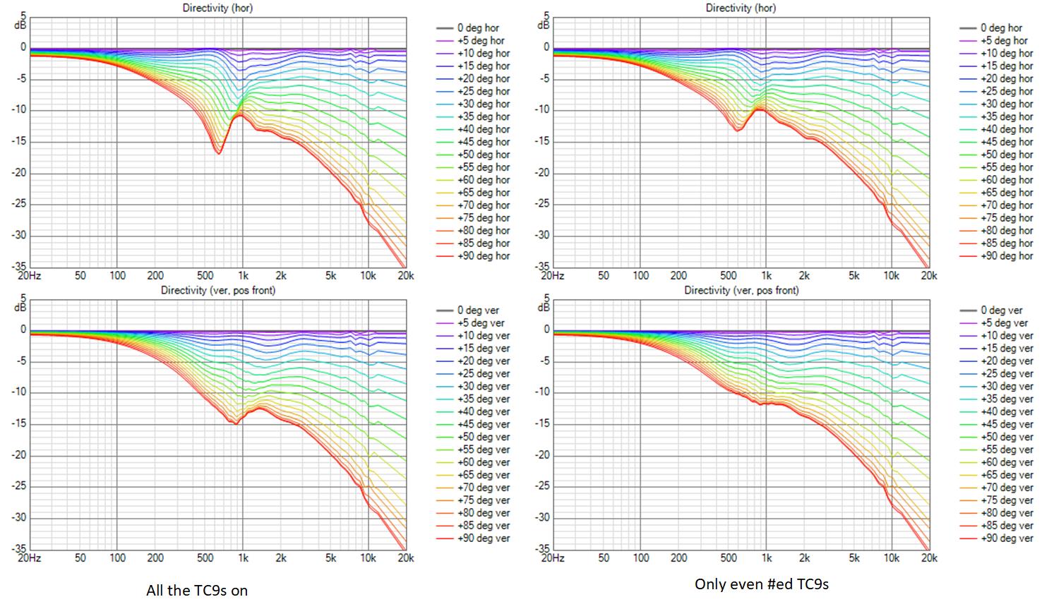
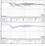
I compared normalized line charts with half the TC9s muted vs all of them on. Normalizing meant I didn't need to change equalization. I was surprised to find that its smoother with half the drivers, with the difference being larger the further off axis one goes. With odd numbered drivers muted, horizontal polars are affected differently than vertical; a reduced number of drivers could be repositioned (rotated 15 degrees) to keep the array symmetrical with respect to the axes.
I've been playing the mids from 200 Hz up, assisted by woofer at floor level playing up to 275 Hz in the last iteration, so 6 mids of almost any size will be sufficient especially at the relatively low SPLs you (fluid) and I have expressed preference for. The bandpass holes or slots through the horn walls won't need to be very large.
Attachments
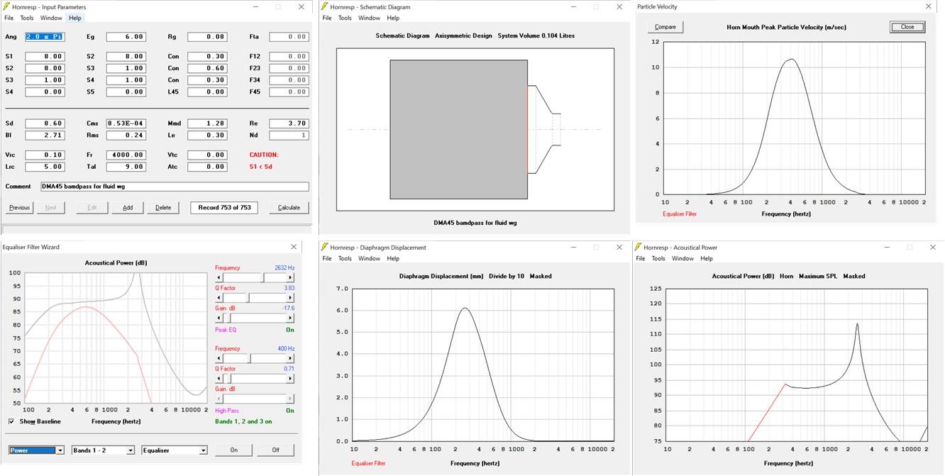
I took another look at the HR sim of a BP TC9. In HR, I used a hole area of 4 cm2. When I did the Vituix model, I used an area of 10 cm2. At the limit, limited by particle velocity in the hole/slot, it appears that 1 cm2 is sufficient.
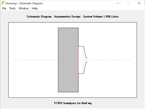
I've got an air cushion in front of the cone and am allowing a total horn wall thickness of .9 cm. This doesn't appear to be especially critical but I will be happy to adjust based on anticipated construction details.
My next step is to add a floor level woofer to the Vituix sim, equalize and then determine the drive level of an individual TC9 when system is producing something like 100 db SPL
Attachments
Here are the HR sim details and the correlation with the Vituix sim
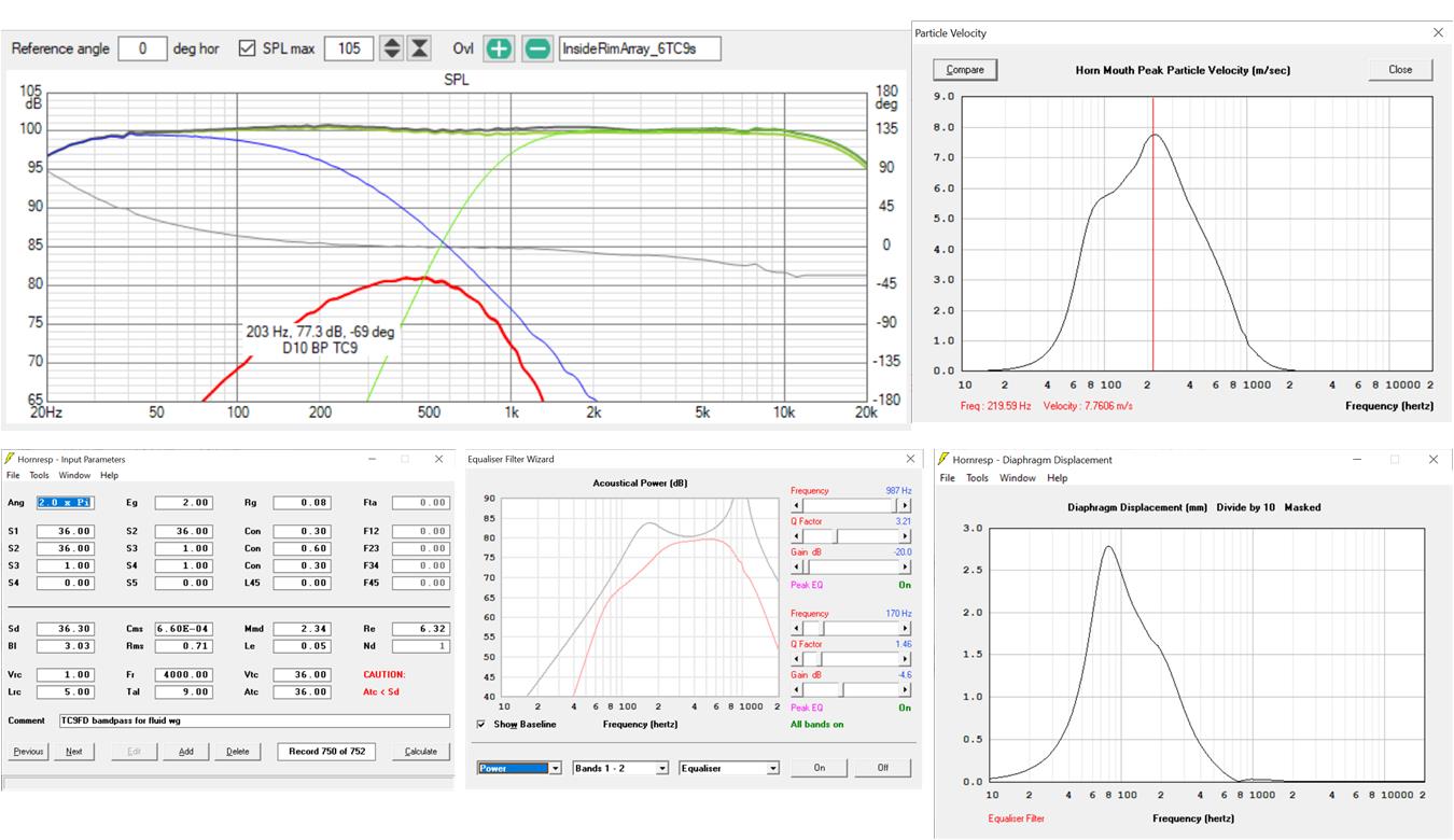
The HR sim level is above the Vituix TC9 spl level at and near the particle velocity peak.
I will get a much better correlation by exporting the raw bandpass response from HR and do the filtering in Vituix. I'll do this at the same time as reducing the port hole size (diaphragm size) in the Vituix model. This will make the array look very much like an array of point sources ...
Attachments
Last edited:

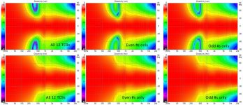
Notice that as good as these polars are in other respects, they show pattern control "only" down to 400 Hz or so. That shows up as a problem when I look at room response vs offset. They will need additional drivers outside the wg to get back to the vertical control of rim arrays. Fortunately, it seems from these sims that 6 drivers per ring is sufficien.
yeah, almost
Yesterday's question was how to increase the vertical directivity. The first answer that came to mind was to add rows of drivers at +/- 360 mm, twice the distance of those in the ring.
That was encouraging so I took a closer look
I think the response above 400 Hz is as good as can be expected with a 60V waveguide, without floor and ceiling absorption. Below 200 Hz, the variation could be improved with more drivers at even greater vertical separation but the room is going to dictate what is needed there.
Attachments
Here is the crossover screenshot:
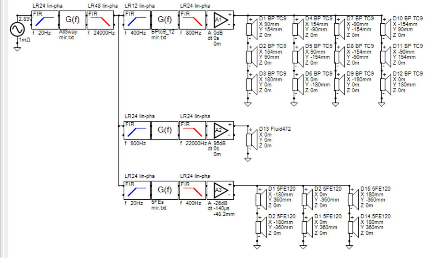
there is a level of global eq that eventually would be used for voicing. right now all it corrects is 1-1.5 db dips near the crossover points.
Note that there is no overlap in this XO. The TC9s play 400 to 800 Hz. Limited to that range, smaller, lighter drivers may be more appropriate. The <$8 Dayton DMA45, which was one of my original line array candidates comes to mind.
Dayton Audio DMA45-4 1-1/2" Dual Magnet Aluminum Cone Full-Range Driver 4 Ohm
this driver is only 1" deep, weighs .15 lbs, and needs only .002ft3 sealed volume, which is why I will try it next
Attachments
the DMA45 HR sim looks good; better than that of the TC9. The bandpass peak is well outside the passband and only simple HP and LP filters are needed to shape the response. Its 1/4th the compression necking down from an SD of 9 to an aperture of 1 cm2. The drawback is the DMA45 is only 80 db sensitive. In the current sim we are driving each of 6 TC9s to an 80 db level to get 103 db total SPL. The HR sim below shows the individual max output is 93 db
Attachments
1 1/2", 2mm x-max? For that frequency band?
2,6 gram, 36,3 cm2 x 2.55mm x-max vs 1,3 gram, 8.6 cm2 x 2mm x-max?
So 4 of those would have similar Sd, still not similar x-max and moving mass would be 2x the weight of the single TC9. I don't see how that would bring down the weight, relatively speaking. Except for the drivers themselves.
2,6 gram, 36,3 cm2 x 2.55mm x-max vs 1,3 gram, 8.6 cm2 x 2mm x-max?
So 4 of those would have similar Sd, still not similar x-max and moving mass would be 2x the weight of the single TC9. I don't see how that would bring down the weight, relatively speaking. Except for the drivers themselves.
Last edited:
That frequency band is 400 Hz to 800 Hz; hence considering DMA45. Rejected the idea earlier when the band was 200 Hz to 800 Hz.
The DMAs are weaker but particle velocity won't all full strength of TC9 to be used through 1 cm2 port. DMAs are at .6 mm X at 103 db SPL, roughly one third of linear Xmax. TC9s would be at 1/4th? of that.
If the physical/mechanical design doesn't say the smaller device fits better, so to speak, I guess we should stick with the TC9s. Fluid though is trying to find homes for his recently purchased 5" Sicas.
They (the Sicas) should be able to do 400-800 too?
I guess it would be nice to find out how to use the least amount of drivers (hence holes in the waveguide) to solve the directivity pattern?
I guess it would be nice to find out how to use the least amount of drivers (hence holes in the waveguide) to solve the directivity pattern?
as to the weight, TC9 is .7 lbs, DMA45 is .15 lbs.
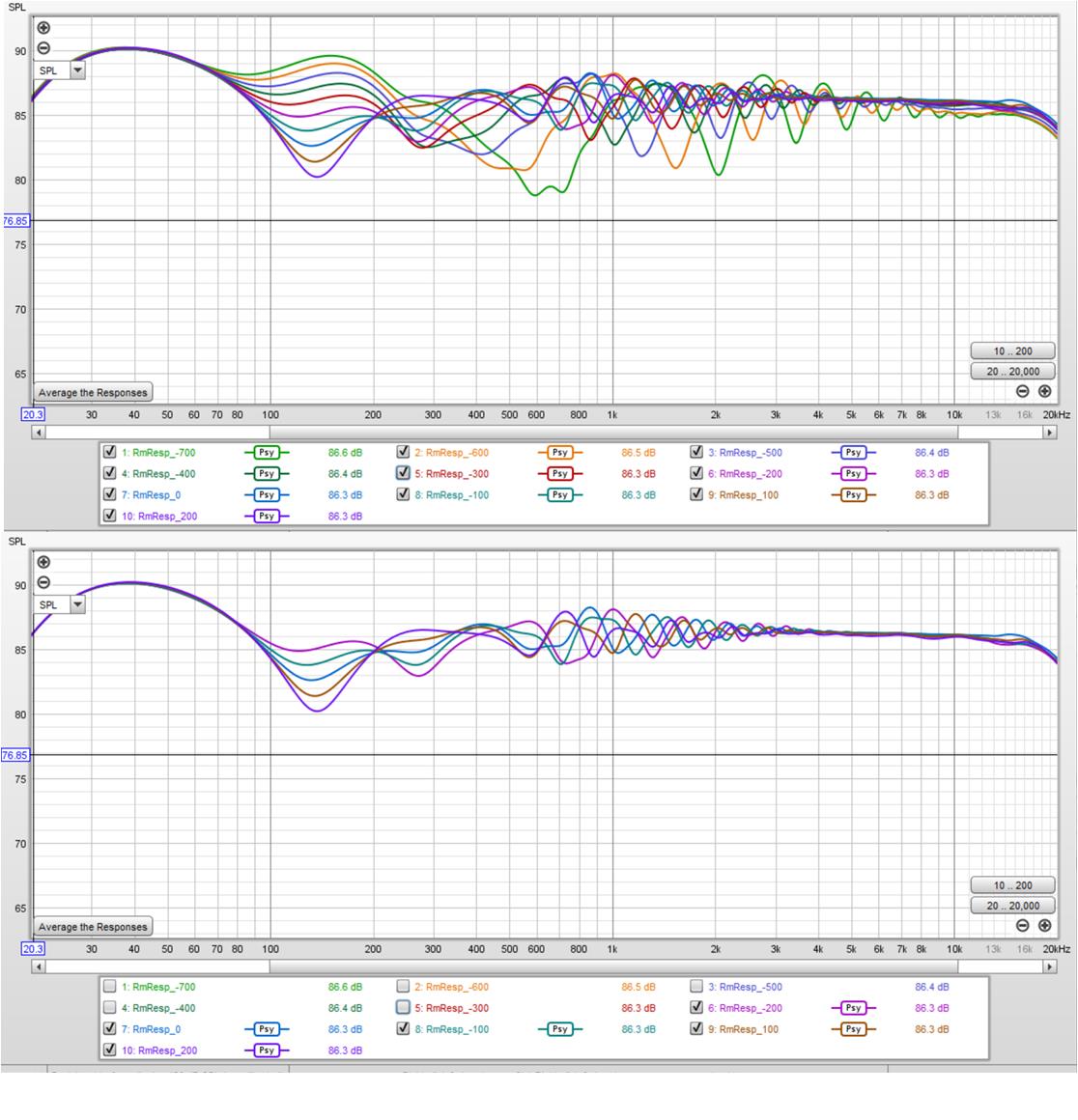
Now looking at 8 drivers, since leaving out the 6 and 12 pm or 1 and 3 pm drivers costs a little bit in directivity; variation with offset came out 1 db higher
8*.7=5.6; 8*.15 = 1.2; difference is 4.4 lbs wasn't talking about cone weight or weight per equivalent displacement as can't use all that TC9 has
I'm looking to minimize hole diameter on the theory that the hole has to be a significant fraction of the wavelength before it affects the frequency.
Also holes will attenuate at the helmholtz resonant frequency, per David McBean. At some point need to look at it from that point of view.
I would be concerned that the hole size appropriate for a 5" driver would be too large except given the anticipated frequency range, a 5" driver isn't appropriate for inside the rim. I'm working 5" drivers into the 100Hz to 400 Hz solution - an array outside the wg.
They (the Sicas) should be able to do 400-800 too?
I guess it would be nice to find out how to use the least amount of drivers (hence holes in the waveguide) to solve the directivity pattern?
I meant to quote you for the last post. Had I done so, I would not have missed making this next point
If the inside the rim drivers are going to be within single point combination distance, then you can get by with 1 or 2 depending on SPL requirements. Since they are definitely not going to combine into a single point, then you need to apply the same CTC distance requirements to spacing around a ring as you would to drivers on a line array. There will be a minimum driver requirement depending on the upper frequency limit. (going out on a limb because I haven't done that calculation 🙂 I tried reducing to 6 drivers, saw an incremental degradation, am increasing to 8 drivers on the 180 mm radius ring.
I guess it's just me, but if we put holes in an almost perfect waveguide (performance wise), I'd want as little holes as possible and would look to continue that single source behavior if possible.
As it would act as one under more than one angle if we use it within 1/4 wave spacing.
Removing the lobes etc. But I would like to see how the tiny holes (but more in numbers) would affect the waveguide behavior. with wider placement to compare.
I'd also opt for a more elliptical shaped waveguide to start with a less wide vertical pattern and wider horizontal. Or seeing the recent Tritonia waveguide (rectangle) it would have more options to play with placement of both drivers and holes.
The question remains what the desired pattern control should be.
And if and how we can optimize hole shape/size within a waveguide. to keep the pattern as good as can be. These waveguides are performing a lot cleaner than the usual Synergy conical's. Optimizing them for that use would be a dream come true.
The first examples start to appear, but the tools are there to find out what hole shape/placement does the least damage.
Its not just you but I don't think you are facing up to the tradeoffs that you would have to confront in trying to achieve those desires.
My simulation of mid array inside the rim at 180mm radius didn't show any lobes until quite a ways off axis.
Its not the number of holes, at least I don't think it is. I think its
total hole area and hole location - the further away from the apex the better. From HornResp, hole area seems to be roughly proportional to SPL and low frequency extension. By limiting WG+rim array to 400 Hz ++, I'm minimizing hole area. By locating those holes 180 mm from apex, I'm minimizing their effect. This still needs to be verified in ABEC and then the real world. And don't forget, the reflection null cancellation has to prove out.
Going for a 100 Hz Synergy would require ~4x higher aggregate hole size and locating those holes so a point source would be created would make them more harmful to a wider frequency range then the same hole area out near the rim.
My goal is to design a system that doesn't have a ground null due to the CD/wg at seated ear height and has a wide vertical listenable window. If done with a single point source, that requires a huge horn, an example is the 48" wide conical Mark100 has described. I don't have room for such behemoths in my house so I'm trying to get same or better results with a reasonable sized waveguide augmented by arrays of small drivers.
These should handle 400Hz with ease and pretty efficient also. I've seen them sell for 30Euro...
Test Lautsprecherchassis Breitbander - Monacor SPX-20TB
Test Lautsprecherchassis Breitbander - Monacor SPX-20TB
- Home
- Loudspeakers
- Full Range
- Full range line array for wall or corner placement