I know your comment is directed at Mark, nevertheless I've been pondering the issue myself.
The way Vituix works I'm simulating a finite line but I can get a room response that includes floor and ceiling reflections, which gives a result equivalent to a 3x longer line but only at a reference angle. It doesn't show me what happens to the vertical directivity. It does show increased "squiggles" on axis due to the reflections.
Combine driver beaming at HF with the increased angle to higher order reflections and frequency tapering definitely occurs in real systems regardless by default. I have to review werewolf's thread but I think the derivation was from omni-direction point sources.
What someone needs to do is bring the frequency tapered array indoors and measure there. That might even be me after I build the 2nd array. Meanwhile I'll be doing more sims.
Let it run full range first, and use some FIR EQ on it and see/hear how you'd like that. You guys forget about how this FFT/IR thing works? Of course you're going to see that train of impulses before trying to re-create a Dirac pulse from (whatever high pass you want) up to 20 KHz.
Do read the Werewolf thread, and remember that we are looking at a bandwidth limited version of his analysis, and yes, with a limited number of sources as well.
Last edited:
The true infinite line has unlimited sources and bandwidth. Hence the shape of it's impulse. However our "as build" line array does not feature an unlimited number of drivers and has a limited bandwidth. This is exactly what the IR shows with that series of impulses. (it's how the IR shows it)
Now to rectify this we would need to follow this advise to stay true to the topic of an infinite array:
Source: https://www.diyaudio.com/forums/multi-way/314917-infinite-line-source-analysis-18.html#post5306341
Which is what I have been trying to get across. I'm sorry to see that the fear of raw impulses have led you guys away from the 'infinite goal'. DRC-FIR isn't that hard guys... and it's free... In other words, like I've said before, it is supposed to look like a train of impulses arriving at the listening (or mic) position before EQ. That is the theory we should have taken/learned from the infinite line source thread.
Heck, email me (PM for details) the impulse and I'll show you what it looks like after DRC...
Hi wesayso, just can't agree to that.
I know werewolf is a really great mathematician, and has forgot more about line arrays than i know....
But theory ain't practice....that's what's askew here...nobody is trying to achieve his perfect dirac pulse.
Heck, the best processors can't even do that.
Imo we are looking for a dirac pulse from our speakers that is as close to a 20-20kHz pulse that we can get from a really good DAC.
So I cannot see that bandwidth is the issue with our finite arrays ...
The issue imho is how far does what we build vary from theory...
And I have to say DRC-FIR is not the answer...for me anyway.
I want to be able to make measurements independently of the FIR generator that uses them, and to understand exactly what corrections the FIR generator is making.
Honestly, it's pretty simple imho...we can fix minimum phase anomalies. but for time domain anomalies, we can only smooth around, or optimize to a spot.
I don't want a black box doing this. If all I'm doing is trying different settings in my FIR generator, it seems to me I might as well just be twisting knobs on something I don't understand till I hear what i like best....
Sure, I know we can make perfect impulses or response curves with our FIR generators....but at what degree of smoothing or windowing, and at what degree of tuning to a spot?
That's the problem I have with solutions like FIR-DRC. Make sense at all? 🙂
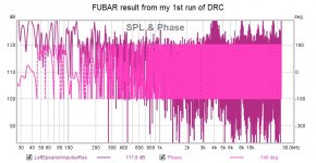
Hi Mark thanks cool test report 😛 for shading graph is that a sound nervous or clever bird pooping in perfect time

Haha, you caught it BYRTT !!
Thank you nc535
And thanks for the sims I'm still trying to fully digest.
Great discussion, really appreciate various all the viewpoints 🙂
And thanks for the sims I'm still trying to fully digest.
Great discussion, really appreciate various all the viewpoints 🙂
Changed the first, highest XO freq to 15 kHz and got better vertical directivity. There seems to be a tradeoff: minimizing that vertical lobing in the HF comes at the cost of narrowing the vertical directivity

But keep in mind these results are for a finite array. An array extended by floor and ceiling reflections would have different and better directivity, especially in the low end.
But keep in mind these results are for a finite array. An array extended by floor and ceiling reflections would have different and better directivity, especially in the low end.
Let it run full range first, and use some FIR EQ on it and see/hear how you'd like that. You guys forget about how this FFT/IR thing works? Of course you're going to see that train of impulses before trying to re-create a Dirac pulse from (whatever high pass you want) up to 20 KHz.
Do read the Werewolf thread, and remember that we are looking at a bandwidth limited version of his analysis, and yes, with a limited number of sources as well.
As I said before, we are in the gap between infinite line source theory and finite source summation as done in a program like Vituix. We are seeing both in simulation and measurement that HF response suffers from the limited number of sources and experimenting with ways to improve it. Ultimately I at least will use DRC-FIR to optimize my response in room; today I made a pass through FEW FDW5 autoEQ to Rephase to JR.
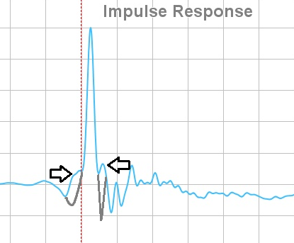
This train of impulses thing is the least of my concerns. I brought up the ringing in my IR, which doesn't look anything like a chain of impulses, thinking it might imply something wrong with my equipment or methodology. Seeing how flattening the FR cleaned it right up, at least at the measurement spot was an aha moment for me as previously I'd only looked in the IR for evidence of reflections.
You know as well as I that these arrays are well short of infinite length in performance. If nothing else, we've seen ra7's measurements at constant distance, various heights. I believe one can tell the effective length by the frequency at which the -3db per octave roll off starts; there is a formula in one of the many papers I've read that I need to dig up. Once I got that number I would do a summation of the equivalent number of drivers, except that Vituix currently limits me to 64, which isn't quite enough.
So really, we aren't heretics; we are simply trying to nail down the difference between theory and practice.
Hi wesayso, just can't agree to that.
I know werewolf is a really great mathematician, and has forgot more about line arrays than i know....
But theory ain't practice....that's what's askew here...nobody is trying to achieve his perfect dirac pulse.
Heck, the best processors can't even do that.
Imo we are looking for a dirac pulse from our speakers that is as close to a 20-20kHz pulse that we can get from a really good DAC.
So I cannot see that bandwidth is the issue with our finite arrays ...
The issue imho is how far does what we build vary from theory...
And I have to say DRC-FIR is not the answer...for me anyway.
I want to be able to make measurements independently of the FIR generator that uses them, and to understand exactly what corrections the FIR generator is making.
Honestly, it's pretty simple imho...we can fix minimum phase anomalies. but for time domain anomalies, we can only smooth around, or optimize to a spot.
I don't want a black box doing this. If all I'm doing is trying different settings in my FIR generator, it seems to me I might as well just be twisting knobs on something I don't understand till I hear what i like best....
Sure, I know we can make perfect impulses or response curves with our FIR generators....but at what degree of smoothing or windowing, and at what degree of tuning to a spot?
That's the problem I have with solutions like FIR-DRC. Make sense at all? 🙂
Not for me, sorry. What do we see in an IR predominantly? The high frequency info, that's the train of impulses we see in a raw impuls from the array with a limited number of sources. An infinite array would have an infinite trace of these and still need work too, to get it back in shape for listening. As the pulse shown is the example of that theoretical infinite line source and it is clearly showing a tail. (It's not a STEP shown)
I had typed in a lot more, but I only have one piece of well meant advise for you, go with the bent CBT. It does not need as much work out in the room, the IR will probably scare you less, even though you're still looking at multiple arrivals, they will be hidden way more than in the IR of the RAW straight array prior to correction.
If nc535 wants to try, I'm here to help. But he may be swayed towards shading already.
As I said before, we are in the gap between infinite line source theory and finite source summation as done in a program like Vituix. We are seeing both in simulation and measurement that HF response suffers from the limited number of sources and experimenting with ways to improve it. Ultimately I at least will use DRC-FIR to optimize my response in room; today I made a pass through FEW FDW5 autoEQ to Rephase to JR.
This train of impulses thing is the least of my concerns. I brought up the ringing in my IR, which doesn't look anything like a chain of impulses, thinking it might imply something wrong with my equipment or methodology. Seeing how flattening the FR cleaned it right up, at least at the measurement spot was an aha moment for me as previously I'd only looked in the IR for evidence of reflections.
You know as well as I that these arrays are well short of infinite length in performance. If nothing else, we've seen ra7's measurements at constant distance, various heights. I believe one can tell the effective length by the frequency at which the -3db per octave roll off starts; there is a formula in one of the many papers I've read that I need to dig up. Once I got that number I would do a summation of the equivalent number of drivers, except that Vituix currently limits me to 64, which isn't quite enough.
So really, we aren't heretics; we are simply trying to nail down the difference between theory and practice.
Fair enough, and I wouldn't describe you guys that way 🙂. Just know a 5 cycle REW FDW isn't close to what DRC gets at those numbers, plus I'd advise using a longer window up top.
What would be more practical than dealing with what you've got?
Don't doubt what you have, based on what the sims tell you. Get your feet wet and take the measurement trough DRC... I've even posted my templates and everything to get you going. I'm willing to help do it and warn you where the pitfalls are. Just get me a measurement and I'll return the prediction.
Fire up your best speakers, measure both of them at once and measure at your ear position one by one. Now you can start to wonder how that can still sound good! Seriously! It does explain why a number of people are preferring mono. The IR isn't going to be pretty there. I'm so glad we have a brain in the middle of these ears 🙂.
If nothing else, we've seen ra7's measurements at constant distance, various heights. I believe one can tell the effective length by the frequency at which the -3db per octave roll off starts; there is a formula in one of the many papers I've read that I need to dig up.
That would have more to do with the driver than with the line theory. A TC9 doesn't give us 20 to 20K output to try. Maybe we should measure one driver, anechoic measurement. Correct it and use that as a pre-condition first for the entire array. Then look at what a line of those does. That would be the fair way.
Just don't measure it outside, as that would turn it back into finite territory. (lol)
If you take a TC9 and correct it, you've got a flat response. No point in measuring if you are just going to correct it, except for the directivity.
Why not start with that flat response and apply piston directivity to it, using the TC9's effective diameter. You can do that in Vituix down to 1 degree steps with little effort; its what I've been doing but with Sb65's diameter.
Unless you'd prefer to measure in 1 degree steps...(you would witness how you built your towers 🙂)
I see so many problems in simulation of a corner line array, that I consider it as waste of time and energy. Modern dsp-correction based on several measurements of the line in it's final placement is what I would do. (Yes, I am a mathematically challenged person)
If you take a TC9 and correct it, you've got a flat response. No point in measuring if you are just going to correct it, except for the directivity.
Why not start with that flat response and apply piston directivity to it, using the TC9's effective diameter. You can do that in Vituix down to 1 degree steps with little effort; its what I've been doing but with Sb65's diameter.
Unless you'd prefer to measure in 1 degree steps...(you would witness how you built your towers 🙂)
No desire to do that while having the real model in my living room to play with.
You have one model ready, go finish the other and really start playing with it. 😀
No desire to do that while having the real model in my living room to play with.
You have one model ready, go finish the other and really start playing with it. 😀
I second that. I , too , have a real model in my living room. And it is , despite all theories, and with the help from wesayso, working really well.
Exactly, and I would have said that myself except that I thought it would have diluted my point about the difficulty of accurate simulation or even mathematical modelling when taking driver directivity into account.No desire to do that while having the real model in my living room to play with.
You have one model ready, go finish the other and really start playing with it. 😀
Still, its always good to correlate measurements with simulations and simulation can amplify the information in a limited set of correlated measurements. In addition, my wife hates the rumble/chirp sound of a sweep so it behooves me to minimize her exposure to it or the garage may become my dedicated sound room🙂
In my own defense, I wired my first array to be unshaded. What convinced me to do this was that so many of you have reported success with unshaded arrays. Plus the system is so much simpler unshaded. Unshaded is likely where I will end up. (reminding myself) sims showed that FIR could "de-squiggle" the IR of an unshaded array and gave an indication over how wide an area the correction would hold. Sims also showed that the narrowing of directivity with shading could be taken too far.
Still shading is interesting so I may continue to explore it
while I wait for the CNC shop to get around to my second set of cabinet parts. Doing this does increase my understanding of the theory and its limitations and I'm as interested in that as in having a new set of speakers.
I had typed in a lot more, but I only have one piece of well meant advise for you, go with the bent CBT. It does not need as much work out in the room, the IR will probably scare you less, even though you're still looking at multiple arrivals, they will be hidden way more than in the IR of the RAW straight array prior to correction.
So I stayed hid under the covers last night, to keep those scary IR's from getting me ! 🙄
No seriously wesayso 🙂, ....please don't take some objective analysis of measurements as criticizing or complaining about the arrays.
Just trying to learn, down to the core, how these lines actually work, both indoors and out, in both corners and out in room.
I could go on again, why I think IR's are important for (me at least) understanding the nature of the arrays HF/VHF radiation...but I don't think there is anything much to add to what's already been said.
I'm quite pleased with the TC9 arrays. They have a beautiful midrange, with a wide smooth sound.
And I feel like I'm learning a heck of alot (which was my stated goal in building these from the gitgo).
All along with making a bunch of new friends !
Cheers

mark
Took another pass thru MiniDSP and REW auto EQ => JR convo
and did some more listening. I'm getting the feeling that this might become a very special speaker. However REW auto EQ is disappoining. It was only a marginal improvement to my manual EQ, which I did quickly, thinking REW would refine it.
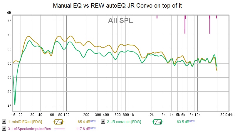
So time to move on to DRC!
I got DRC to run with little trouble. I exported my miniDSP eq measurement as wav from REW, changing its file type to .PCM as required by DRC. DRC ran with no error messages and produced a result. I imported the result back into REW.
This is what I got (you guys need a laugh)
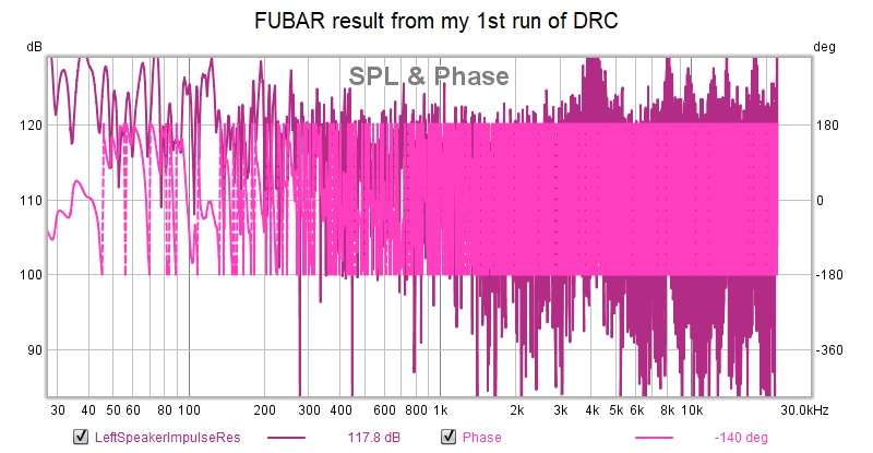
I'm sure I'm making a rookie error. In fact, looks like a GIGO problem, garbage in- garbage out.
Very little guidance is provided. I just dropped my IRs into the samples folder and clicked on Normalxx.bat.
I did notice DRC seems to produce result for 44.1 khz sampling rate whereas I am set up for 96 khz. I'm not sure what to do about that.
Help appreciated.
and did some more listening. I'm getting the feeling that this might become a very special speaker. However REW auto EQ is disappoining. It was only a marginal improvement to my manual EQ, which I did quickly, thinking REW would refine it.
So time to move on to DRC!
I got DRC to run with little trouble. I exported my miniDSP eq measurement as wav from REW, changing its file type to .PCM as required by DRC. DRC ran with no error messages and produced a result. I imported the result back into REW.
This is what I got (you guys need a laugh)
I'm sure I'm making a rookie error. In fact, looks like a GIGO problem, garbage in- garbage out.
Very little guidance is provided. I just dropped my IRs into the samples folder and clicked on Normalxx.bat.
I did notice DRC seems to produce result for 44.1 khz sampling rate whereas I am set up for 96 khz. I'm not sure what to do about that.
Help appreciated.
Attachments
Last edited:
Oh. Didn't see errors in the bat but there is a warning I overlooked
!!Warning: input signal too short for correct signal prewindowing, spurious spikes may be generated.
Boy, I'll say. Maybe be I should read the guidance on how to produce an IR for DRC; thought I already knew that...
... oops ...
there is a prep step in Audacity I need to do
!!Warning: input signal too short for correct signal prewindowing, spurious spikes may be generated.
Boy, I'll say. Maybe be I should read the guidance on how to produce an IR for DRC; thought I already knew that...
... oops ...
there is a prep step in Audacity I need to do
Last edited:
Yes, that is apparent but not how to fix it. My first attempt at hacking the bat file resulted in a file not found error. Does it care about the sample rate of the input?
No, but one should use the template that belongs to that sample rate. Have you looked at the available templates? If it (the template) does not exist one should be created with the proper variables.
Look at Greg's (gmad) thread and sample templates. I only have 44100 in use myself.
You could start with one of his samples.
He provided a complete package with his own batch files etc. It would be a good start.
Look at Greg's (gmad) thread and sample templates. I only have 44100 in use myself.
You could start with one of his samples.
He provided a complete package with his own batch files etc. It would be a good start.
- Home
- Loudspeakers
- Full Range
- Full range line array for wall or corner placement