Those graphs assume wave propagation follows spherical geometry irrespective of what is happening around it. Fluid dynamics isn't so simple. Each wavefront alters the pressure gradient along its boundary, and this slightly distorts the geometry of another wavefront crossing it.
For typical designs and reasonably spaced drivers this is negligible and interference occurs very close to simple models. But when drivers are tightly spaced and there are dozens of them, those slight distortions add up and become significant.
It isn't that interference doesn't occur, but rather that the coalescence to a unified wavefront occurs closer than simple models predict and the wavefront farfield is more uniform than predicted.
Those graphs assume wave propagation follows spherical geometry irrespective of what is happening around it. Fluid dynamics isn't so simple. Each wavefront alters the pressure gradient along its boundary, and this slightly distorts the geometry of another wavefront crossing it.
For typical designs and reasonably spaced drivers this is negligible and interference occurs very close to simple models. But when drivers are tightly spaced and there are dozens of them, those slight distortions add up and become significant.
It isn't that interference doesn't occur, but rather that the coalescence to a unified wavefront occurs closer than simple models predict and the wavefront farfield is more uniform than predicted.
Isn't what you describe how individual drivers are able to act like a line source where spacing is tight enough relative to a wavelength?
You mention far field but we listen to line arrays in our homes in their near fields, although the 3 or 4m that is near field for a line array wouldn't be considered near field for other types of speakers.
I agree the situation isn't as bad as predicted by simple models. Its frustrating that we can't make better predictions. Still, if we didn't have "squiggles" to account for and try to massage away, what would there be to do?
Yes. An array of drivers can't quite act like a line source until you are really far away (what you refer to as far field), but they don't act identical to a collection of point sources either. The interaction is more complex.
Yes. An array of drivers can't quite act like a line source until you are really far away (what you refer to as far field), but they don't act identical to a collection of point sources either. The interaction is more complex.
Now this is interesting.
I thought to simulate an array in xls would be easy. Just calculate the spl/phase additions at the listening point since distances to each driver(phase diffrence of each driver), spl of each driver are known. Its just a phasor/vector sum.
But, you are saying thats not all. So, how does one simulate it to sufficient accuracy. What are the formulae, in simple terms please?
Wouldn't it be great if that really happened? Like I said, I no longer buy into that explanation, which is why I prefer the floor to ceiling array for different reasons.
This text might be interesting to some:
https://apps.spokane.edu/InternetContent/AutoWebs/pamelam/meyer_line_array%20theory%20fact%20myth.pdf
Not trying to sway anyone's opinion here. Believe what you will. I'm just trying to make sense of what I see happening out in my 'real world'.
This text might be interesting to some:
https://apps.spokane.edu/InternetContent/AutoWebs/pamelam/meyer_line_array%20theory%20fact%20myth.pdf
Not trying to sway anyone's opinion here. Believe what you will. I'm just trying to make sense of what I see happening out in my 'real world'.
For a strait infinite line source shouldn't werewolf's thread be some of the bible itself : )
LINK: https://www.diyaudio.com/forums/multi-way/314917-infinite-line-source-analysis.html#post5246393
If i remember correct nobody could point a real negative finger at his math and theory back at that time, myself is very positive about infinite line source probably because i heard wesayso's wonders twice, and if wesayso one day go north guess we will be welcome hear koldby's system : ) but myself pulled a planned infinite woofer array after learning at that thread that a mix with a point source then loss of SPL per doubling of distance wouldn't be the same.
But the thing is, and this is my frustration, what we build only approaches that infinite line source in the limits as the driver spacing goes to zero and the floor and ceiling approach perfect reflectivity. We are left trying to bridge the gap between this math and limited accuracy of driver summation approach.
But the thing is, and this is my frustration, what we build only approaches that infinite line source in the limits as the driver spacing goes to zero and the floor and ceiling approach perfect reflectivity. We are left trying to bridge the gap between this math and limited accuracy of driver summation approach.
I completely agree.
And it is why I bullheadedly rely on basic measurements (along with careful listening of course), to understand the realities of not being able to implement the ideals embodied in theory. Ideals such as infinite line length, infinitesimal driver spacing, etc.
About to try to make some outdoor measurements like discussed yesterday.
One 'rule of thumb' for multiways is that far field summation starts at about 3x the longest frontal dimension of the speaker.
Intend to test the arrays today, past that distance too.
Wouldn't it be great if that really happened? Like I said, I no longer buy into that explanation, which is why I prefer the floor to ceiling array for different reasons.
This text might be interesting to some:
https://apps.spokane.edu/InternetContent/AutoWebs/pamelam/meyer_line_array%20theory%20fact%20myth.pdf
Not trying to sway anyone's opinion here. Believe what you will. I'm just trying to make sense of what I see happening out in my 'real world'.
Thanks for that paper. The author apparently has access to or has created better line array simulation software than we have (really impressive software on a second reading but commercially oriented). We are left forming beliefs based on imperfect knowledge, which is OK provided we modify those beliefs with results of experiments/experience.
I don't think we have to give up our belief in superposition, a fundamental principle of linear systems analysis, to employ the cylindrical wave description of line array behavior. We just have to appreciate the fact that its an approximation with accuracy that decreases with frequency.
Now this is interesting.
I thought to simulate an array in xls would be easy. Just calculate the spl/phase additions at the listening point since distances to each driver(phase diffrence of each driver), spl of each driver are known. Its just a phasor/vector sum.
But, you are saying thats not all. So, how does one simulate it to sufficient accuracy. What are the formulae, in simple terms please?
There is no simple formula unfortunately. This falls into the realm of computational fluid dynamics.
As an example to help visualize what I'm saying... take the case of a single speaker with wave propagation approaching a hard enclosure corner. Simple point source math (sine function, distance) to determine spl at a location ignores the refraction and reflection we know the corner generates. There is some bending of the wavefront around the corner and some refraction from the edge itself.
Similarly, one wave alters the local gradient and has an effect on the propagation of an adjacent wavefront in a way more complex than simple interference.
There are online 2D simulators that can show interaction of more than one wavefront reasonably well. When sources get close the CFD approximation methods get less and less accurate but still show interactions more complex than simple summation. True solutions take hardcore software and time.
And I agree... real measurements of what your drivers are doing in your enclosure always trump simulation!
I don't think we have to give up our belief in superposition, a fundamental principle of linear systems analysis, to employ the cylindrical wave description of line array behavior. We just have to appreciate the fact that its an approximation with accuracy that decreases with frequency.
I think this is a perfect and succinct way of saying it and a practical approach we have no choice but to follow.
Ran into some problems with my setup. Somehow after messing with it I now get our local radio station😱.
I would be able to measure some things in room as I'm using a full line array of SB65WBAC25-4 but Mark's measurements would be more telling.
Let me know if you want any specific in-room measurements performed as I'd be happy to run a few. The more minds the better.
I would be able to measure some things in room as I'm using a full line array of SB65WBAC25-4 but Mark's measurements would be more telling.
Let me know if you want any specific in-room measurements performed as I'd be happy to run a few. The more minds the better.
For a strait infinite line source shouldn't werewolf's thread be some of the bible itself : )
LINK: https://www.diyaudio.com/forums/multi-way/314917-infinite-line-source-analysis.html#post5246393
If i remember correct nobody could point a real negative finger at his math and theory back at that time, myself is very positive about infinite line source probably because i heard wesayso's wonders twice, and if wesayso one day go north guess we will be welcome hear koldby's system : ) but myself pulled a planned infinite woofer array after learning at that thread that a mix with a point source then loss of SPL per doubling of distance wouldn't be the same.
I agree here, the thread from werewolf is a must read for anyone serious enough to consider getting floor to ceiling arrays.
I'm not at all pessimistic about the line array, but you've got to be aware of what you're dealing with. For those among us that use full range drivers, you've got to know they do things rather different than a tweeter would up high. I've said a few times in the past and will say it again, you don't want to array drivers with a ringing top end. Both the SBA and Vifa are a safe bet.
All of these things matter, I merely posted the simple graphs to show there isn't much sense in assuming or determining a minimum 1/2 wavelength between drivers, as the distance to the array will be even more important. Sure we want to mimic a seamless array, but with a bit of work we can actually get quite close. Mark, if you want to know where to start shading, those circles I've drawn would be a good starting point. That's the point of posting them. No more, no less.
For those not yet playing with the FIR tools like DRC-FIR, Acourate or Audiolense yet, get off your butts and start using it! Really! You haven't heard anything yet if you haven't played with the combination of arrays and software like this. I have heard so many different ways of how these arrays can produce sound, it takes getting to know it all to make the decisions about what you want them to do.
Judging from the quote from BYRRT, I'm not the only one to think that it is quite possible to get great sound out of them.
There are way more things to worry about than the result of the raw IR, as that hardly tells us anything.
These results shouldn't even be news worthy, as there are plenty of array owners that have shown their results.
The strange thing is, we don't hear them complaining here, do we? Embrace what you've got, work on it to make it better. That has played out well enough for me. And I'm quite sure I'm not the only one who's content with the results they got.
OK, got in some outdoor testing despite lawn movers, a computer crash that lost nearly 20 REW measurements, and a bird perched on the array, probably pooping 🙄
No real surprises or revelations regarding distance to mic...simply more confirmation of what we've all been discussing.
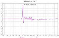
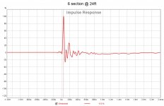
Impulse squiggles diminish with distance to mic, and/or with reduced number of sections. High end freq response oscillations showed same patterns.
It's all totally consistent with multi-arrivals in my casual assessment.
I measured at two distances, 15 and 24 ft. Full array impulses are below.
Not gonna bother with posting reduced sections again, as it repeats the same pattern as previously posted.
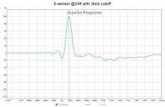
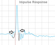
What was fun, and new for me, was looking at impulse with HF/VHF truncation. I started with a 5kHz cutoff as it seemed that's where freq response breakup begins. But then I said heck, why not do it by wavelengths..
So I simply stopped the REW sine sweeps at various wavelength intervals using a TC9 center to center of 3.06". Impulse got progressively cleaner with a march down thru 4, 2, 1, 3/4, 1/2, and 1/4 W/L's.
Best looking impulses were in the 1/2 to 3/4 WL range. 3kHz is shown below for full array at 24ft.
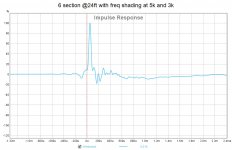
Last, I used the truncated impulse info gathered, to attempt a first stab at frequency shading.
The center two sections stayed full range. The next two were low-passed at 5kHz.
The top and bottom sections were low-passed at 3kHz. LPF were 100 dB/oct linear phase. Delays were set to bring the line back to straight-line timing. Shown below, last plot.
For me, looking at these impulse plots is a must to help decide what to tune and what not. It's time domain info that appears to matter much more than what I'm used to with multi-ways....
I mean Ron, if distance to array is the most import thing, it tells me that multi-arrivals exist big time....and makes me wonder why I even pay attention to infinite line theory.
It seems like I'm throwing away more valid instruction by disregarding 1/2 to 1 W/L spacing, than I am by disregarding infinite line theory.
But it does appear that line theory may work really well down low, particularity with floor-to-ceiling.
I guess a big part of the education here, is learning how full-range drivers fit or don't fit the whole line idea. So on I trudge 🙂
No real surprises or revelations regarding distance to mic...simply more confirmation of what we've all been discussing.
Impulse squiggles diminish with distance to mic, and/or with reduced number of sections. High end freq response oscillations showed same patterns.
It's all totally consistent with multi-arrivals in my casual assessment.
I measured at two distances, 15 and 24 ft. Full array impulses are below.
Not gonna bother with posting reduced sections again, as it repeats the same pattern as previously posted.
What was fun, and new for me, was looking at impulse with HF/VHF truncation. I started with a 5kHz cutoff as it seemed that's where freq response breakup begins. But then I said heck, why not do it by wavelengths..
So I simply stopped the REW sine sweeps at various wavelength intervals using a TC9 center to center of 3.06". Impulse got progressively cleaner with a march down thru 4, 2, 1, 3/4, 1/2, and 1/4 W/L's.
Best looking impulses were in the 1/2 to 3/4 WL range. 3kHz is shown below for full array at 24ft.
Last, I used the truncated impulse info gathered, to attempt a first stab at frequency shading.
The center two sections stayed full range. The next two were low-passed at 5kHz.
The top and bottom sections were low-passed at 3kHz. LPF were 100 dB/oct linear phase. Delays were set to bring the line back to straight-line timing. Shown below, last plot.
For me, looking at these impulse plots is a must to help decide what to tune and what not. It's time domain info that appears to matter much more than what I'm used to with multi-ways....
I mean Ron, if distance to array is the most import thing, it tells me that multi-arrivals exist big time....and makes me wonder why I even pay attention to infinite line theory.
It seems like I'm throwing away more valid instruction by disregarding 1/2 to 1 W/L spacing, than I am by disregarding infinite line theory.
But it does appear that line theory may work really well down low, particularity with floor-to-ceiling.
I guess a big part of the education here, is learning how full-range drivers fit or don't fit the whole line idea. So on I trudge 🙂
Attachments
What did you just measure, a finite or infinite line? 🙄
And never the two shall meet 🙂
Really cool Mark, you are making me a believer. It wouldn't be that hard to rewire mine for tapering.
I now have a Vituix simulation of a frequency tapered array following your pattern.
I have the array divided into 4 groups of 8. The 8 center most first, then successively add 4 drivers to the ends until you run out of drivers.
I am using linear phase LR2 low pass filters rather than brickwall. When I tried brickwall each filter gave a spike at its XO frequency. The XOs I used were 8k, 4k and 2k. Little attempt at optimization.
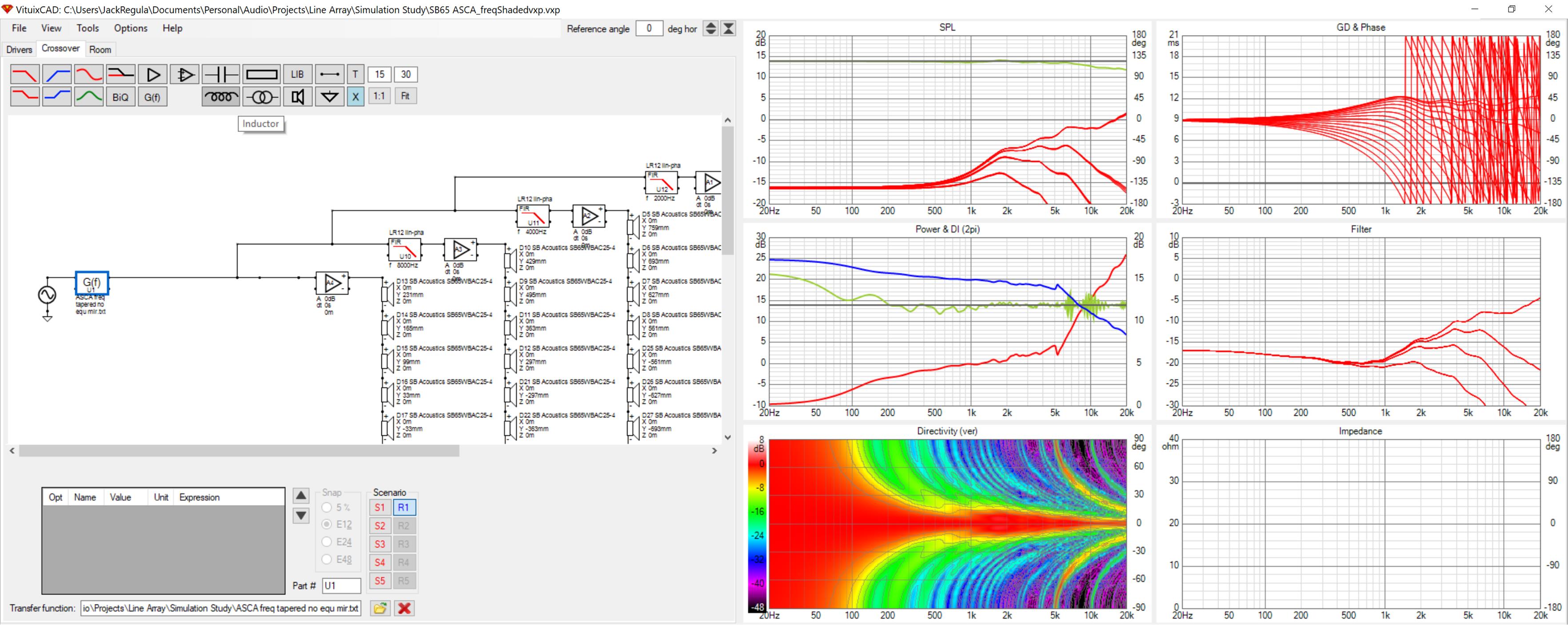
Note how the vertical directivity narrows in the frequency tapered region. That might not be a problem because out at 4m listening distance, _/-5 degree vertical window is 700mm tall. We should make sure the untapered part of the array starts below seated ear height and extends beyond standing ear height.
The flat grey lines in the top graph are the freq and phase directly on axis. The light green line there is the listening window average, which is set to only 5 degrees vertically. With the window set to 10 degrees, the average is worst case -4db where its 2 db for a 5 degree vertical window.
The green line in the middle graph is the room response including floor and ceiling reflections. There are +/-3db squiggles in it. The way to frequency taper floor and ceiling reflections would be with thin treatments.
I love having a simulation that can fill in for a limited set of measurements.
I now have a Vituix simulation of a frequency tapered array following your pattern.
I have the array divided into 4 groups of 8. The 8 center most first, then successively add 4 drivers to the ends until you run out of drivers.
I am using linear phase LR2 low pass filters rather than brickwall. When I tried brickwall each filter gave a spike at its XO frequency. The XOs I used were 8k, 4k and 2k. Little attempt at optimization.
Note how the vertical directivity narrows in the frequency tapered region. That might not be a problem because out at 4m listening distance, _/-5 degree vertical window is 700mm tall. We should make sure the untapered part of the array starts below seated ear height and extends beyond standing ear height.
The flat grey lines in the top graph are the freq and phase directly on axis. The light green line there is the listening window average, which is set to only 5 degrees vertically. With the window set to 10 degrees, the average is worst case -4db where its 2 db for a 5 degree vertical window.
The green line in the middle graph is the room response including floor and ceiling reflections. There are +/-3db squiggles in it. The way to frequency taper floor and ceiling reflections would be with thin treatments.
I love having a simulation that can fill in for a limited set of measurements.
Attachments
Hi Mark thanks cool test report 😛 for shading graph is that a sound nervous or clever bird pooping in perfect time 
Attachments
Last edited:
And never the two shall meet 🙂
I know your comment is directed at Mark, nevertheless I've been pondering the issue myself.
The way Vituix works I'm simulating a finite line but I can get a room response that includes floor and ceiling reflections, which gives a result equivalent to a 3x longer line but only at a reference angle. It doesn't show me what happens to the vertical directivity. It does show increased "squiggles" on axis due to the reflections.
Combine driver beaming at HF with the increased angle to higher order reflections and frequency tapering definitely occurs in real systems regardless by default. I have to review werewolf's thread but I think the derivation was from omni-direction point sources.
What someone needs to do is bring the frequency tapered array indoors and measure there. That might even be me after I build the 2nd array. Meanwhile I'll be doing more sims.
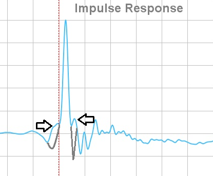
Let's see that horrible raw pulse again from the supposed infinite line:
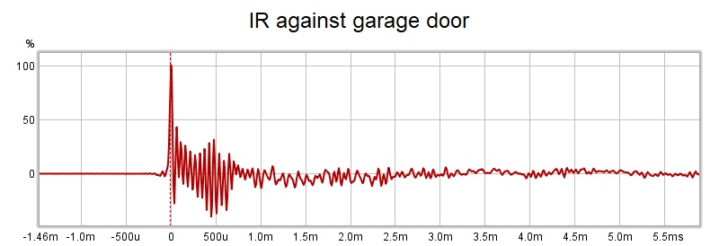
Now let's look at what the true infinite line is supposed to look like:
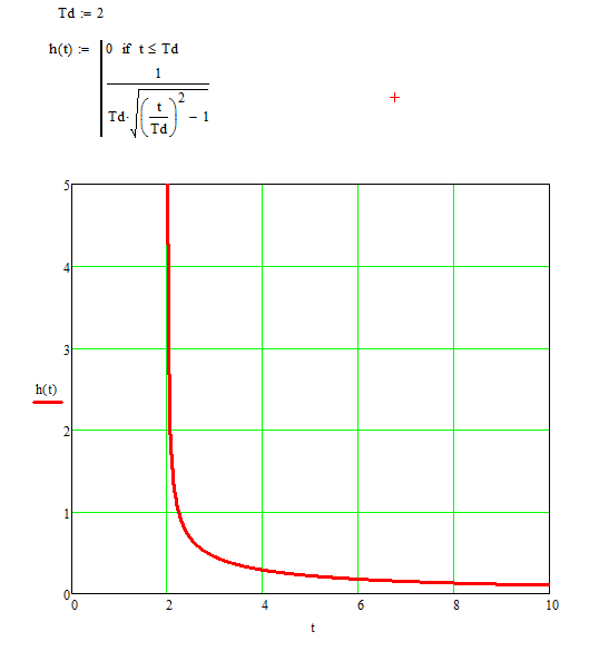
Source: https://www.diyaudio.com/forums/multi-way/314917-infinite-line-source-analysis-19.html#post5308524
Anybody dare to guess about the reasons for the differences here?
The true infinite line has unlimited sources and bandwidth. Hence the shape of it's impulse. However our "as build" line array does not feature an unlimited number of drivers and has a limited bandwidth. This is exactly what the IR shows with that series of impulses. (it's how the IR shows it)
Now to rectify this we would need to follow this advise to stay true to the topic of an infinite array:
Source: https://www.diyaudio.com/forums/multi-way/314917-infinite-line-source-analysis-18.html#post5306341
Which is what I have been trying to get across. I'm sorry to see that the fear of raw impulses have led you guys away from the 'infinite goal'. DRC-FIR isn't that hard guys... and it's free... In other words, like I've said before, it is supposed to look like a train of impulses arriving at the listening (or mic) position before EQ. That is the theory we should have taken/learned from the infinite line source thread.
Heck, email me (PM for details) the impulse and I'll show you what it looks like after DRC...
Now let's look at what the true infinite line is supposed to look like:
Source: https://www.diyaudio.com/forums/multi-way/314917-infinite-line-source-analysis-19.html#post5308524
Anybody dare to guess about the reasons for the differences here?
The true infinite line has unlimited sources and bandwidth. Hence the shape of it's impulse. However our "as build" line array does not feature an unlimited number of drivers and has a limited bandwidth. This is exactly what the IR shows with that series of impulses. (it's how the IR shows it)
Now to rectify this we would need to follow this advise to stay true to the topic of an infinite array:
I have a question: can we, at a theoretically fixed listening distance, apply an inverse transfer function to get back to the Dirac pulse at that specific listening distance? Effectively EQ-ing the line back to "flat" response?
In a word, no 🙁 but ... we don't need to 😉
To equalize the impulse response back to a Dirac impulse ... or, alternatively, to equalize back to "flat" frequency response ... would require enormous (essentially, infinite) dynamic range. We have to remember that a truly "impulsive" impulse response corresponds to a frequency response that's flat ... not just over 20kHz, but "from DC to Daylight".
HOWEVER ... we don't need a flat frequency beyond beyond 20kHz 🙂 And there's already plenty of filters in the audio processing chain (below 20Hz, above 20kHz) that will already deviate the impulse response from the idealized Dirac impulse. All we really need from the loudspeaker, is "reasonably flat" frequency response over 20kHz ... and the corresponding impulse response will be just fine 🙂 and that is something that IS possible ...
For example ... recognizing that we probably won't be using a line source in the sub-bass, or maybe even low-bass, regions ... let's say we want to use a line source over the top seven (7) octaves of the human hearing range. The natural frequency response of the Infinite Line Source ... falling at -3dB per octave ... means that we'll need about 20dB of dynamic range to equalize 'flat' over 7 octaves. That's not too crazy, i think ...
Source: https://www.diyaudio.com/forums/multi-way/314917-infinite-line-source-analysis-18.html#post5306341
Which is what I have been trying to get across. I'm sorry to see that the fear of raw impulses have led you guys away from the 'infinite goal'. DRC-FIR isn't that hard guys... and it's free... In other words, like I've said before, it is supposed to look like a train of impulses arriving at the listening (or mic) position before EQ. That is the theory we should have taken/learned from the infinite line source thread.
Heck, email me (PM for details) the impulse and I'll show you what it looks like after DRC...
Last edited:
- Home
- Loudspeakers
- Full Range
- Full range line array for wall or corner placement