I downloaded everthing or thought I did. The bat files have configurable parameters for sample rate, apparently. Wouldn't be surprised if not all the rates have been tried. I'm not really a programmer so I can't dig too deep. The config file gets called somewhere inside the drc executable but I got lost before I found it.
I might have fixed it. the normal-96.0.drc that it couldn't find wasn't the config file but a file needed in the sample directory. I created normal-96.0.drc from a normal-441.1drc by changing all the 441s to 960s and now it runs to completion.
past that error anyway; still not right....tomorrow
past that error anyway; still not right....tomorrow
Last edited:
I'll try and attach a normal96000.drc template to this post. All values should be different, meaning it would more than double the size of all numbers in the 44100 template. (values are dependent on sample rate)
I don't think the window sizes in the "normal" template are any good though. They are kind of long and not very suitable for in room correction. I just browsed trough my templates from gmad, all I have on disk from him are 44100 sample rate.
You could do as I did, and start with DRCDesigner: Digital Room Correction Designer Help
I did not use the recording part of this program but for me this was the start of playing with window sizes and targets. It does include all sample rate templates. It is based on a slightly older version of DRC-FIR though. I recall it being one version behind when I started using it. I just copied the latest files over the DRCDesigner sub directories to rectify that. The custom tab lets you create your own window lengths. It is that feature that I have used extensively to find my desired window lengths. Around the time Gmad started his thread I moved on to my own batch files that pretty much automate the whole process for me except for the IR measurement.
For a start it should help you play with some quick parameters like window size and target. You can draw your own target.
Here's a link to my files: https://www.diyaudio.com/forums/full-range/242171-towers-25-driver-range-line-array-150.html#post4501046
Some things did change though, I would be happy to share the current template and settings i use, but they are all at 44100. I let JRiver upsample the correction (it does so automatically) when playing high res songs. The majority in my library is 44100 sample rate so I stuck with that.
Attachments
Last edited:
Thanks for all that; it will likely take me a while to digest.
I like the Digital DRC Designer help; it actually explains more than just what each control does. Gives me hope.
I don't understand how it works to let JR upsample. My sound card works at 96 khz so my impulses are at that sample rate and the output has to be at that rate. I thought my only choice was to configure JR to re-sample all the sources to 96. Certainly seemed like the thing to do before I tried DRC 🙂
DRC Designer help says it will only create filters at the sample rate of the impulse....
perhaps it would be easier to resample my IRs to 44.1 and the filters to 96, although I'm not sure what tool would do that. Audacity perhaps? Just used it for first time yesterday...
Here is what I get from the Normal96000.drc. Is that what you expected?
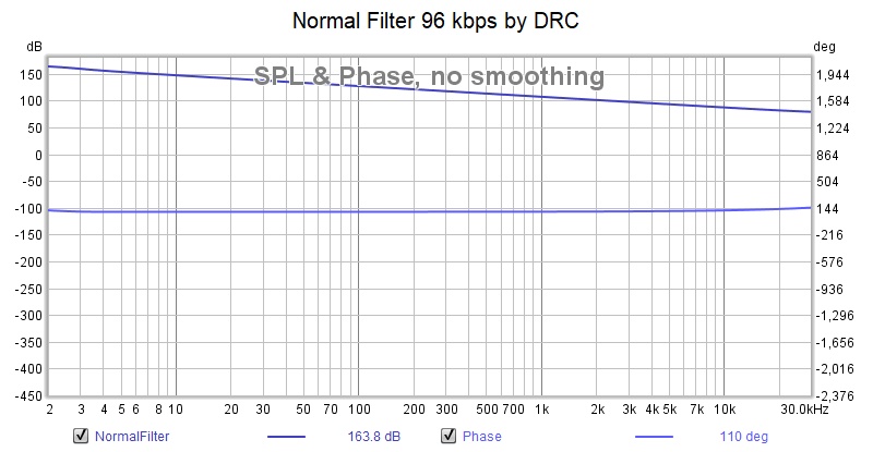
As you implied, its not doing any room correction, seems to be just applying a target file and flattening the phase (lower trace).
It looks like what I was getting last night with my hacks, although I may have missed something.
For the record, I
** created a script for the data rate by going through the 44.1 script and changing all the 44.1s to 96.0s and 44100s to 96000s
** in samples directory
***** created a normal-rate.drc file and a pa-rate.txt file with the same kind of hacks
Moving on to DRC Designer as hacking isn't the right way to live
Attachments
I've got it working, I think, but I've still got a GIGO problem. It looks like I really butchered my IR when I ran it through Audacity. DRC_Designer doesn't ask me to do that so I think I will try with my un-Audacious IRs.
I notice DRC_D uses a painfully long sweep whereas I've got REW set for a chirp 256K sweep. Should I lengthen my sweep?
I notice DRC_D uses a painfully long sweep whereas I've got REW set for a chirp 256K sweep. Should I lengthen my sweep?
not any better with new data not run thru audacity and with longer sweep
DRC produces results but they are slmply straight lines tilted down in frequ domain (and way too much attenuation in high end to make sense) with flat phase
DRC produces results but they are slmply straight lines tilted down in frequ domain (and way too much attenuation in high end to make sense) with flat phase
No idea what kind of an impulse you have used as input, because I never saw a correction being this flat from DC up to 30 KHz+ 😱.
The 96000 template i have uploaded will be quite different from the 44100 internally...
Let's review the first step of the DRC process:
First the 44100 sample rate:
Next the 96000 sample rate:
See how values like BCInitWindow and BCPreWindowlen etc. are longer, the higher the sample rate is? This is part of the frequency dependent windowing DRC uses.
DRC has a few mechanisms going that determine it's output. The NormalXX.drc is an example template and inside of that there will be choices that determine the processing and thus it's outcome.
However it is quite impossible to get the straight (but declining) line you show as an outcome if the input was a real measurement. Still, the outcome is largely depending on the choices made within the template, the microphone calibration you've applied and the template which was chosen. (PSPointsFile)
Within either the template or the batchfile a target is chosen for the total outcome. If I look in my Normal48000.drc template this file points at "pa-48.0.txt"
as the target. Opening this target (found in the sample directory) we see this:
Which means it should be 30 dB down at 0 Hz, -10 dB at 10 Hz, flat from 20 Hz to 20000 Hz and declining from there.
Within DRCDesigner you can draw your ow shapes. Internal settings within DRC's template determine how close it tries to get/stick to that shape.
About the chirp length, I use 1M sweeps with REW. My reasoning being that that longer signal makes it easier to sort random sounds from the real sound of interest. I have a rather high noise floor with even some traffic noise leaking in every now and then and the longer measurement works better/more consistent and repeatable for me.
I'm curious to find out what the input IR was like. It should be something like a 500 ms length IR that has the speaker playing at a reasonable volume to play above noise levels. Personally I use an SPL meter to find out true SPL level by using the Full range calibration sound from REW, so I know the measurements have somewhat of a fixed "real world" reference to them.
The declining frequency response (which just cannot be right) may be caused by internal choices made within this template.
Here are the different steps inside the template:
BC = Base Configuration
MC = Microphone Compensation stage
HD = Homomorphic Deconvolution
MP = Minimum phase Prefiltering stage
DL = Dip Limiting stage
EP = Excess phase Prefiltering stage
PC = Prefiltering Completion stage
IS = Inversion Stage
PT = Psychoacoustic Target
PL = Peak Limiting
RT = Ringing Truncation stage
PS = Postfiltering Stage
MS = Minimum phase filter generation Stage
TC = Test Convolution stage
In my own template I actually choose to bypass a few of these steps. For instance, I do not use the "PT" part, the "Psychoacoustic Target".
I've done so by setting: 'PTType = N' which means this step is ignored completely. I've done the same for the "Ringing Truncation stage" or "RT".
All of these steps or stages determine what happens to the IR input file. Every variable that is set within a template can even get an override from the batchfile, so this can further complicate knowing what's really going on.
There's also a prediction feature (TCOutFile), it lets DRC predict what the measurement is going to look like after correction. This is quite accurate in my experience. It is only activated if a name has been given to that TCOutFile variable. For instance: "TCOutFile=c:\DRCDesigner\LcustTest.pcm"
What it does is it takes the input and it 'convolves' that result with the DRC generated FIR file.
I think it would be worthwhile to look into that thread by Gmad I've linked. That thread contains a step by step work trough and explains a lot of what you can expect.
Using DRCDesigner might work OK too, but if you measure with REW, you need to place the files in the right directory with the name DRCDesigner expects to find. You can see these files after running DRCDesigner, probably in the PCM format and named something like "LeftSpeakerImpulseResponse96000.pcm" for the left speaker. Once you have those files in place for both left and right speaker you can run multiple DRCDesigner tests and they will each create a convolution FIR file.
As said, i no longer use DRCDesigner, but for me, it was the easiest way to try a few different things. For a long time I used the SoftXX.drc template and made some changes to that where I thought I needed it. The "Generate Custom Filters" tab within DRCDesigner allowed me to play with variables for the actual frequency dependent window to use. It did so by making a temporary batch file with overrides while using one of the templates (determined by: Load template) for the rest of the variables. This output was done in readable text (inside the .bat DRCDesigner created) and gave me insight of what it was doing and why/how. That's how I learned the basics. And lots of reading in the manual from DRC to learn what each of the variables stood for.
Nowadays I use one batch file that generates everything I'm interested in in one go. So I just place the left and right files with the right names in PCM format and run the batch file. This then generates the left and right FIR correction files and converts it into a Stereo convolution file to use with JRiver.
First things first:
What the .... are we looking at, from where did you get that graph you posted? What is it? What did you feed into DRC to get it? It does not make any real sense to me.
I don't use Audacity, for the longest time I have been using a program called "Cool Edit Pro". It is an old version but allows me to do quick conversions and edits. The PCM file you store for use within DRC needs to be in the right format. I export my full measurement from REW to a 32 bit wave file, no gating or other things applied, then convert it within Cool Edit to the PCM format for DRC_FIR to do it's thing. The tutorial from gmad (Greg) or perceval should explain how that's done within Audacity.
The 96000 template i have uploaded will be quite different from the 44100 internally...
Let's review the first step of the DRC process:
First the 44100 sample rate:
Code:
# BC = Base Configuration
BCInFile = rs.pcm
BCSampleRate = 44100
BCInFileType = F
BCImpulseCenterMode = A
BCImpulseCenter = 0
BCInitWindow = 131072
BCPreWindowLen = 1024
BCPreWindowGap = 768
BCNormFactor = 0.0
BCNormType = E
Next the 96000 sample rate:
Code:
# BC = Base Configuration
BCInFile = rs.pcm
BCSampleRate = 96000
BCInFileType = F
BCImpulseCenterMode = A
BCImpulseCenter = 0
BCInitWindow = 262144
BCPreWindowLen = 2048
BCPreWindowGap = 1536
BCNormFactor = 0.0
BCNormType = E
See how values like BCInitWindow and BCPreWindowlen etc. are longer, the higher the sample rate is? This is part of the frequency dependent windowing DRC uses.
DRC has a few mechanisms going that determine it's output. The NormalXX.drc is an example template and inside of that there will be choices that determine the processing and thus it's outcome.
However it is quite impossible to get the straight (but declining) line you show as an outcome if the input was a real measurement. Still, the outcome is largely depending on the choices made within the template, the microphone calibration you've applied and the template which was chosen. (PSPointsFile)
Within either the template or the batchfile a target is chosen for the total outcome. If I look in my Normal48000.drc template this file points at "pa-48.0.txt"
as the target. Opening this target (found in the sample directory) we see this:
Code:
0 -30.0
10 -10.0
20 0.00
22.4 0.00
18000 0.00
20000 0.00
22000 -3.00
24000 -30.0
Which means it should be 30 dB down at 0 Hz, -10 dB at 10 Hz, flat from 20 Hz to 20000 Hz and declining from there.
Within DRCDesigner you can draw your ow shapes. Internal settings within DRC's template determine how close it tries to get/stick to that shape.
About the chirp length, I use 1M sweeps with REW. My reasoning being that that longer signal makes it easier to sort random sounds from the real sound of interest. I have a rather high noise floor with even some traffic noise leaking in every now and then and the longer measurement works better/more consistent and repeatable for me.
I'm curious to find out what the input IR was like. It should be something like a 500 ms length IR that has the speaker playing at a reasonable volume to play above noise levels. Personally I use an SPL meter to find out true SPL level by using the Full range calibration sound from REW, so I know the measurements have somewhat of a fixed "real world" reference to them.
The declining frequency response (which just cannot be right) may be caused by internal choices made within this template.
Here are the different steps inside the template:
BC = Base Configuration
MC = Microphone Compensation stage
HD = Homomorphic Deconvolution
MP = Minimum phase Prefiltering stage
DL = Dip Limiting stage
EP = Excess phase Prefiltering stage
PC = Prefiltering Completion stage
IS = Inversion Stage
PT = Psychoacoustic Target
PL = Peak Limiting
RT = Ringing Truncation stage
PS = Postfiltering Stage
MS = Minimum phase filter generation Stage
TC = Test Convolution stage
In my own template I actually choose to bypass a few of these steps. For instance, I do not use the "PT" part, the "Psychoacoustic Target".
I've done so by setting: 'PTType = N' which means this step is ignored completely. I've done the same for the "Ringing Truncation stage" or "RT".
All of these steps or stages determine what happens to the IR input file. Every variable that is set within a template can even get an override from the batchfile, so this can further complicate knowing what's really going on.
There's also a prediction feature (TCOutFile), it lets DRC predict what the measurement is going to look like after correction. This is quite accurate in my experience. It is only activated if a name has been given to that TCOutFile variable. For instance: "TCOutFile=c:\DRCDesigner\LcustTest.pcm"
What it does is it takes the input and it 'convolves' that result with the DRC generated FIR file.
I think it would be worthwhile to look into that thread by Gmad I've linked. That thread contains a step by step work trough and explains a lot of what you can expect.
Using DRCDesigner might work OK too, but if you measure with REW, you need to place the files in the right directory with the name DRCDesigner expects to find. You can see these files after running DRCDesigner, probably in the PCM format and named something like "LeftSpeakerImpulseResponse96000.pcm" for the left speaker. Once you have those files in place for both left and right speaker you can run multiple DRCDesigner tests and they will each create a convolution FIR file.
As said, i no longer use DRCDesigner, but for me, it was the easiest way to try a few different things. For a long time I used the SoftXX.drc template and made some changes to that where I thought I needed it. The "Generate Custom Filters" tab within DRCDesigner allowed me to play with variables for the actual frequency dependent window to use. It did so by making a temporary batch file with overrides while using one of the templates (determined by: Load template) for the rest of the variables. This output was done in readable text (inside the .bat DRCDesigner created) and gave me insight of what it was doing and why/how. That's how I learned the basics. And lots of reading in the manual from DRC to learn what each of the variables stood for.
Nowadays I use one batch file that generates everything I'm interested in in one go. So I just place the left and right files with the right names in PCM format and run the batch file. This then generates the left and right FIR correction files and converts it into a Stereo convolution file to use with JRiver.
First things first:
What the .... are we looking at, from where did you get that graph you posted? What is it? What did you feed into DRC to get it? It does not make any real sense to me.
I don't use Audacity, for the longest time I have been using a program called "Cool Edit Pro". It is an old version but allows me to do quick conversions and edits. The PCM file you store for use within DRC needs to be in the right format. I export my full measurement from REW to a 32 bit wave file, no gating or other things applied, then convert it within Cool Edit to the PCM format for DRC_FIR to do it's thing. The tutorial from gmad (Greg) or perceval should explain how that's done within Audacity.
Last edited:
The weird numbers of DRC_FIR demystified...
If you see something like:
MPLowerWindow = 71040
(taken from a Soft96000 template as an example)
Let's see how that works. DRC divides the IR impulse in an equal length window reserved before and after the peak of the impulse. So the 71040 number includes an equal length window before and after the impulse peak.
From the manual:
So unless "BCImpulseCenterMode" is set to something other than "A" DRC will try and find it automatically and probably expects it somewhere close to the center of the provided PCM file. It will look for the largest peak it can find.
REW exports IR's with the peak centered at 1 second, if it is at t=0 in the IR graph. This is why my "BCImpulseCenterMode" is set to "M" (for manual control) and parameter "BCImpulseCenter=44100" Which means my REW export should have the peak of the impulse centered exactly at 1 second. Let's check that...
Here is my REW measurement, exported the IR to a 32 bit file, imported into Cool Edit it shows the impulse peak centered at 1 second exactly.
This REW export is now saved within the program of my choice to a 32-bit IEEE Float (16.8) PCM file for further processing within DRC.
Now to get back from the DRC template number: 71040 to it's real length in (milli)seconds (should be about 370 ms) we can do as follows:
71040/2= 35520. (dividing the file into a pre and post window on both sides of the IR peak).
So what does that mean if it's coming from a template using a sample rate of 96000?
35520/96000=0.37 seconds or 370 ms. This is the value within the Soft96000 template at 20 Hz. Knowing the 370 ms duration we can work our way back to how many actual cycles we are looking at for the 20 Hz frequency.
370 ms at 20 Hz corresponds to ~7.4 cycles. (a 20 Hz cycle has a duration of 50 ms)
See: Wavelength acoustic sound wave air sound waves frequency calculation temperature wave no air pressure speed of sound - sengpielaudio Sengpiel Berlin
In other words, the magical or mystical numbers in DRC are given in samples, but they reserve an equal number for the window before and after the impulse peak. So if the template says: 71040, it means 71040 divided by 2 = 35520 samples for the frequency dependent window which is used at that frequency.
I hope this helps to show how you can get back to real world numbers. For instance in my own template I have: MPLowerWindow = 35280 which would mean a 400 ms window (at 44100 sample rate). However in my Batchfile you can find the parameter: '--MPLowerWindow=26460' which functions as an override for the value in the template.
Doing the math again:
26460/2=13230 (= number of samples for both the pre and post window)
13230/44100=0.3 (length in seconds, which means 300 ms)
So 300 ms at 20 Hz boils down to 6 cycles at 20 Hz.
I hope this makes all of the abracadabra within DRC a bit more readable. A complete timetable of my own preferred frequency dependent window looks like this:
For the most part these times are shorter than the ones used in even the SoftXX.drc template (way shorter than the NormalXX.drc template!), except for the top end, as an array of drivers will have an obvious delay before the outer most driver actually hits our microphone. This means I actually use about 11.8 cycles of correction at 20 KHz. With the help of DRCDesigner I have tried to find at what point I could not hear any improvement in the top end. The goal was to find the shortest possible window that still got me the best sonic results. ymmv 🙂
DRC actually shows these frequency dependent window tables upon it's generation. I've put in the actual length in ms to the table above to make it more readable.
For a 96000 template you'd need way different numbers (obviously) to get the same length window(s) as I have at 44100. But now you know where it all comes from.
(I hope 😉)
If you see something like:
MPLowerWindow = 71040
(taken from a Soft96000 template as an example)
Let's see how that works. DRC divides the IR impulse in an equal length window reserved before and after the peak of the impulse. So the 71040 number includes an equal length window before and after the impulse peak.
From the manual:
Code:
6.1.5  BCImpulseCenterMode

The impulse response impulse center may be set manually using the BCImpulseCenter parameter or you may ask DRC to try to find it automatically. If BCImpulseCenterMode is set to A DRC will look for the impulse center within the input file. If BCImpulseCenterMode is set to M DRC uses the impulse center supplied with the BCImpulseCenter parameter.
So unless "BCImpulseCenterMode" is set to something other than "A" DRC will try and find it automatically and probably expects it somewhere close to the center of the provided PCM file. It will look for the largest peak it can find.
REW exports IR's with the peak centered at 1 second, if it is at t=0 in the IR graph. This is why my "BCImpulseCenterMode" is set to "M" (for manual control) and parameter "BCImpulseCenter=44100" Which means my REW export should have the peak of the impulse centered exactly at 1 second. Let's check that...
Here is my REW measurement, exported the IR to a 32 bit file, imported into Cool Edit it shows the impulse peak centered at 1 second exactly.
This REW export is now saved within the program of my choice to a 32-bit IEEE Float (16.8) PCM file for further processing within DRC.
Now to get back from the DRC template number: 71040 to it's real length in (milli)seconds (should be about 370 ms) we can do as follows:
71040/2= 35520. (dividing the file into a pre and post window on both sides of the IR peak).
So what does that mean if it's coming from a template using a sample rate of 96000?
35520/96000=0.37 seconds or 370 ms. This is the value within the Soft96000 template at 20 Hz. Knowing the 370 ms duration we can work our way back to how many actual cycles we are looking at for the 20 Hz frequency.
370 ms at 20 Hz corresponds to ~7.4 cycles. (a 20 Hz cycle has a duration of 50 ms)
See: Wavelength acoustic sound wave air sound waves frequency calculation temperature wave no air pressure speed of sound - sengpielaudio Sengpiel Berlin
In other words, the magical or mystical numbers in DRC are given in samples, but they reserve an equal number for the window before and after the impulse peak. So if the template says: 71040, it means 71040 divided by 2 = 35520 samples for the frequency dependent window which is used at that frequency.
I hope this helps to show how you can get back to real world numbers. For instance in my own template I have: MPLowerWindow = 35280 which would mean a 400 ms window (at 44100 sample rate). However in my Batchfile you can find the parameter: '--MPLowerWindow=26460' which functions as an override for the value in the template.
Doing the math again:
26460/2=13230 (= number of samples for both the pre and post window)
13230/44100=0.3 (length in seconds, which means 300 ms)
So 300 ms at 20 Hz boils down to 6 cycles at 20 Hz.
I hope this makes all of the abracadabra within DRC a bit more readable. A complete timetable of my own preferred frequency dependent window looks like this:
Code:
R - Band:   0,    20.0 Hz, width:  13230, FIR, 300,00 ms
R - Band:   1,    25.2 Hz, width:   9821, FIR, 224,48 ms
R - Band:   2,    31.8 Hz, width:   7416, FIR, 167.11 ms
R - Band:   3,    40.0 Hz, width:   5669, FIR, 128,55 ms
R - Band:   4,    50.4 Hz, width:   4373, FIR, 99,95 ms
R - Band:   5,    63.5 Hz, width:   3397, FIR, 76,43 ms
R - Band:   6,    80.0 Hz, width:   2652, FIR, 60,14 ms
R - Band:   7,   100.8 Hz, width:   2080, FIR, 47,07 ms
R - Band:   8,   127.1 Hz, width:   1636, FIR, 37,13 ms
R - Band:   9,   160.1 Hz, width:   1291, FIR, 29,29 ms
R - Band:  10,   201.7 Hz, width:   1021, FIR, 23,12 ms
R - Band:  11,   254.0 Hz, width:    810, FIR, 18,37 ms
R - Band:  12,   320.3 Hz, width:    643, FIR, 14,59 ms
R - Band:  13,   403.6 Hz, width:    512, FIR, 11,60 ms
R - Band:  14,   508.1 Hz, width:    409, FIR, 9,28 ms
R - Band:  15,   640.8 Hz, width:    327, FIR, 7,41 ms
R - Band:  16,   808.8 Hz, width:    262, FIR, 5,94 ms
R - Band:  17,  1019.2 Hz, width:    211, FIR, 4,79 ms
R - Band:  18,  1281.1 Hz, width:    171, FIR, 3,88 ms
R - Band:  19,  1613.4 Hz, width:    139, FIR, 3,15 ms
R - Band:  20,  2045.0 Hz, width:    113, FIR, 2,56 ms
R - Band:  21,  2575.7 Hz, width:     93, FIR, 2,11 ms
R - Band:  22,  3251.2 Hz, width:     77, FIR, 1,75 ms
R - Band:  23,  4132.5 Hz, width:     64, FIR, 1,45 ms
R - Band:  24,  5222.0 Hz, width:     54, FIR, 1,22 ms
R - Band:  25,  6618.6 Hz, width:     46, FIR, 1,04 ms
R - Band:  26,  8279.7 Hz, width:     40, FIR, 0,91 ms
R - Band:  27, 10470.8 Hz, width:     35, FIR, 0,79 ms
R - Band:  28, 13283.5 Hz, width:     31, FIR, 0,70 ms
R - Band:  29, 16635.5 Hz, width:     28, FIR, 0,63 ms
F - Band:  30, 20000.0 Hz, width:     26, FIR, 0.59 ms
For the most part these times are shorter than the ones used in even the SoftXX.drc template (way shorter than the NormalXX.drc template!), except for the top end, as an array of drivers will have an obvious delay before the outer most driver actually hits our microphone. This means I actually use about 11.8 cycles of correction at 20 KHz. With the help of DRCDesigner I have tried to find at what point I could not hear any improvement in the top end. The goal was to find the shortest possible window that still got me the best sonic results. ymmv 🙂
DRC actually shows these frequency dependent window tables upon it's generation. I've put in the actual length in ms to the table above to make it more readable.
For a 96000 template you'd need way different numbers (obviously) to get the same length window(s) as I have at 44100. But now you know where it all comes from.
(I hope 😉)
Attachments
Last edited:
I do realize it can all be a little intimidating upon a first gaze. That's why I try to give you some basic information that I had to find the hard way, by trying to reverse engineer what I saw running down the screen in the DRC process. It made it just that bit more clear what was going on. I've also spend time on Audiolense forums and Acourate to see how it worked there. The phase correction window can be set to different numbers than the frequency correction window and my inspiration actually comes from Audiolense. That window length is way shorter and does not run all the way up to 20KHz in my template, it actually does in the standard templates!
This improved my corrections at the top end, using minimum phase only, while the bottom end is more of a mixed phase correction in my own template. I use a lot of overrides in my batchfile, so my template alone is still not telling all my secrets, only the combination of both will. That's actually a leftover from my days of using DRCDesigner, as I've used the batch files generated by that program and moved on from there. Don't be discouraged by the complexity, take it one step at a time.
First getting DRCDesigner to work, while using REW meaurements would be my advise. You can stick to the 96000 sample rate, but first you need to be sure you are using the measured IR's from REW as input for DRC. I'd also advise to pick a standard template to work from in the "Generate Custom Filters" tab within DRCDesigner (I picked softXX.drc after trying them all) and you can start by changing the windowing.
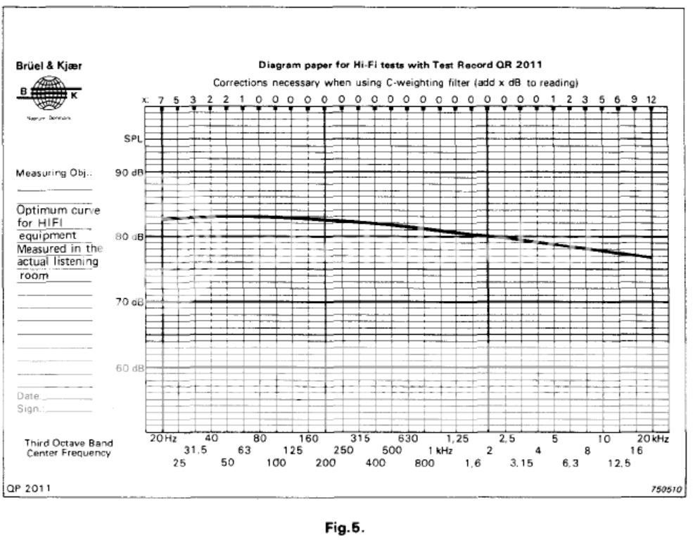
You need to work out a template that works for you. You mentioned the declining target in your post as bad, while I would think it follows the Sean Olive shape quite well (and also Linkwitz) as a target. I've posted my preferences for the JBL preferred curves where the trained listeners curve came closest to what I had found over time. That one certainly isn't flat by any means. But it works quite well in a real room.
a flat frequency response out in my room is me leaving the room screaming for help in no time! 😀 I still play with it though and my latest curve is bending a little up above 10 KHz, but it also depends heavily on mid/side EQ. For first results a B&K curve or something close to the JBL curve (trained listeners) should give you a good start, see how many variation there is in the preferences shown in that curve for trained and casual listeners. This means you've got to find your own, one that works for you in your room.

This improved my corrections at the top end, using minimum phase only, while the bottom end is more of a mixed phase correction in my own template. I use a lot of overrides in my batchfile, so my template alone is still not telling all my secrets, only the combination of both will. That's actually a leftover from my days of using DRCDesigner, as I've used the batch files generated by that program and moved on from there. Don't be discouraged by the complexity, take it one step at a time.
First getting DRCDesigner to work, while using REW meaurements would be my advise. You can stick to the 96000 sample rate, but first you need to be sure you are using the measured IR's from REW as input for DRC. I'd also advise to pick a standard template to work from in the "Generate Custom Filters" tab within DRCDesigner (I picked softXX.drc after trying them all) and you can start by changing the windowing.
You need to work out a template that works for you. You mentioned the declining target in your post as bad, while I would think it follows the Sean Olive shape quite well (and also Linkwitz) as a target. I've posted my preferences for the JBL preferred curves where the trained listeners curve came closest to what I had found over time. That one certainly isn't flat by any means. But it works quite well in a real room.
a flat frequency response out in my room is me leaving the room screaming for help in no time! 😀 I still play with it though and my latest curve is bending a little up above 10 KHz, but it also depends heavily on mid/side EQ. For first results a B&K curve or something close to the JBL curve (trained listeners) should give you a good start, see how many variation there is in the preferences shown in that curve for trained and casual listeners. This means you've got to find your own, one that works for you in your room.
Ok, I did see a zipfile with your impulse included. As I'm not set to do 96000 sample rate, I converted the file to a sample rate of 44100 (not ideal but fun for a few tests).
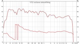
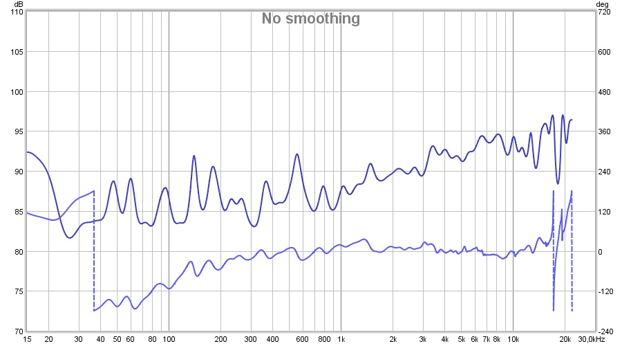
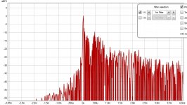
First the raw impulse as uploaded (and converted to 44100) into REW:
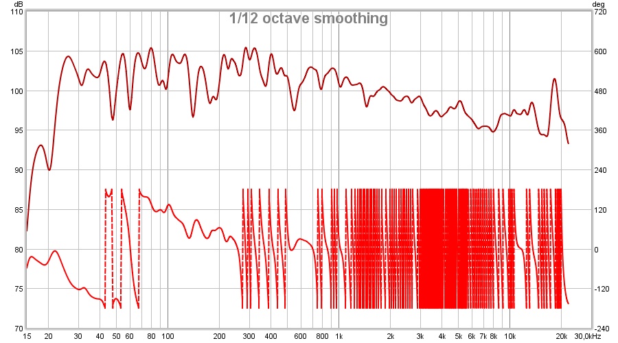
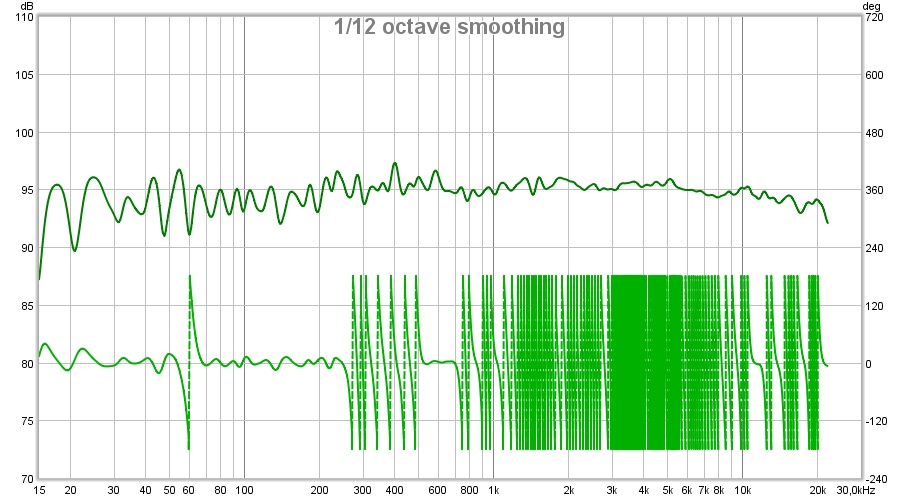
Smoothed 1/12, you should see something similar to this, right?
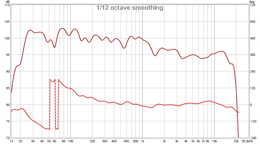
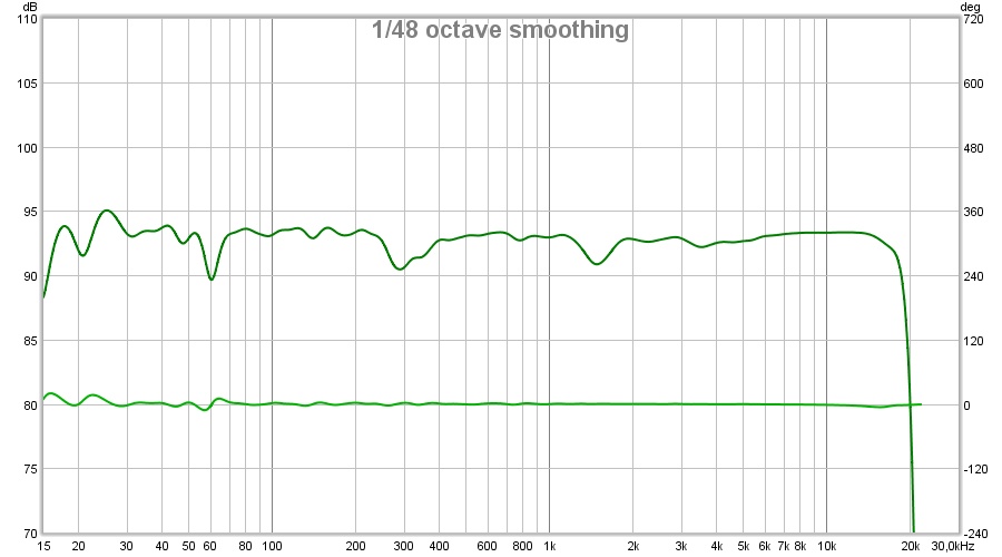
Next the same data but with a 6 cycle window:
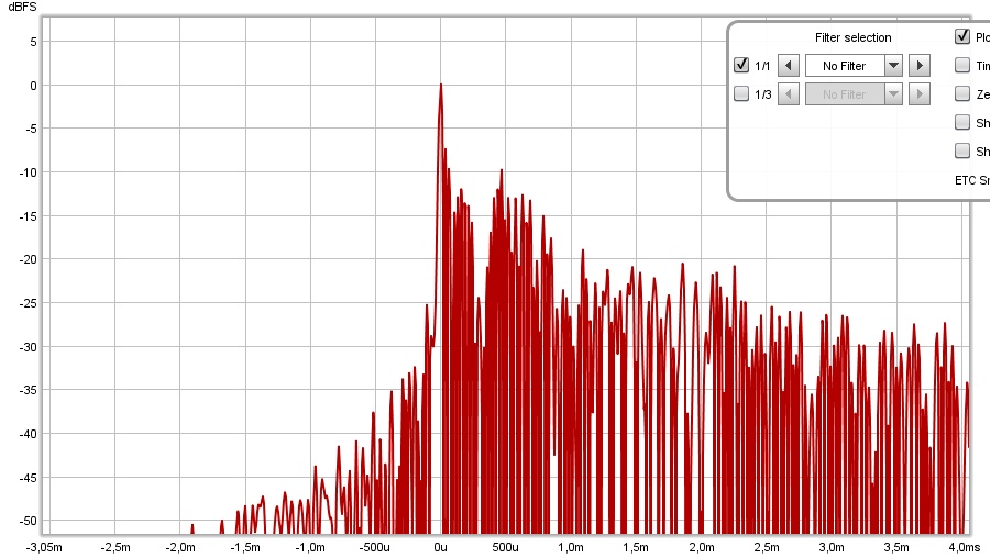
The IR you've uploaded:
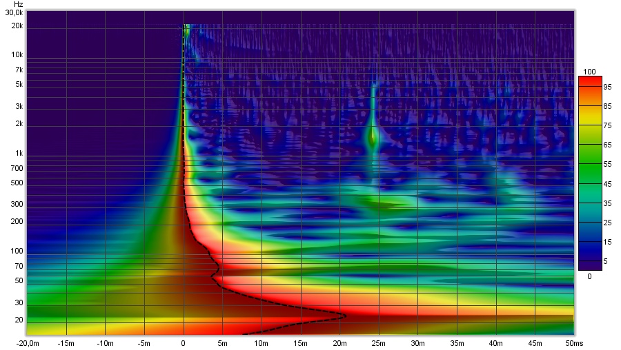
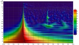
And finally what it looks like in a wavelet, set to show timing (comparable to what APL_TDA shows us)
As I now had acces to the file, I ran it trough my settings. Let's see the results, I used a flat target (flat.txt) for these.
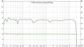
First the corrected frequency response:
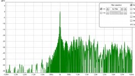
The same view, but this time with a 6 cycle window:
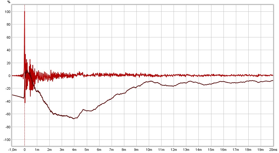
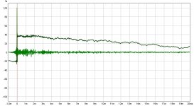
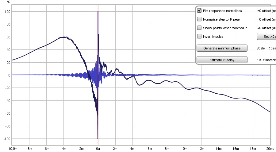
The resulting IR after correction:
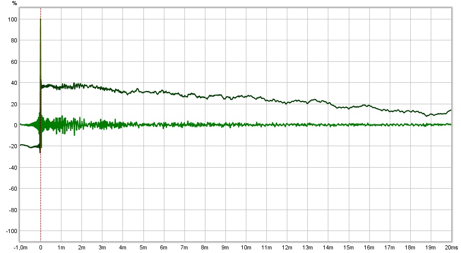
See how the STEP keeps flying with this flat target? Quite close to what a Dirac pulse would do.
And how it looks in the wavelet:

If this IR is something you've measured indoors in your home, and the other side is acting similar you're in for a treat 😀. Not bad at all, but how is this array of even smaller drivers than the TC9 doing at 20 Hz distortion wise? Is this with a sub running or an array by itself? Do check distortion graphs with correction applied, this looks quite nice though as a prediction!
Your IR looks quite clean for the first few miliseconds! It looks clean overall and only shows something happening at 24 ms (nice as a Haas kicker (lol)).
If you can get both arrays to perform like this, you're in for a big big smile once you find your specific room curve/target and variables within DRC.
First the raw impulse as uploaded (and converted to 44100) into REW:
Smoothed 1/12, you should see something similar to this, right?
Next the same data but with a 6 cycle window:
The IR you've uploaded:
And finally what it looks like in a wavelet, set to show timing (comparable to what APL_TDA shows us)
As I now had acces to the file, I ran it trough my settings. Let's see the results, I used a flat target (flat.txt) for these.
First the corrected frequency response:
The same view, but this time with a 6 cycle window:
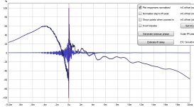
The resulting IR after correction:
See how the STEP keeps flying with this flat target? Quite close to what a Dirac pulse would do.
And how it looks in the wavelet:
If this IR is something you've measured indoors in your home, and the other side is acting similar you're in for a treat 😀. Not bad at all, but how is this array of even smaller drivers than the TC9 doing at 20 Hz distortion wise? Is this with a sub running or an array by itself? Do check distortion graphs with correction applied, this looks quite nice though as a prediction!
Your IR looks quite clean for the first few miliseconds! It looks clean overall and only shows something happening at 24 ms (nice as a Haas kicker (lol)).
If you can get both arrays to perform like this, you're in for a big big smile once you find your specific room curve/target and variables within DRC.
Attachments


Low frustration tolerance is more of a problem than intimidation. I never hesitate to jump in.
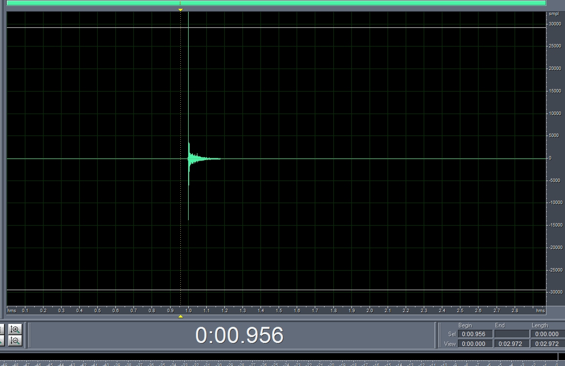
But I've traced the problem. Stage by stage results are good until I export from Audacity as instructed in the guide.
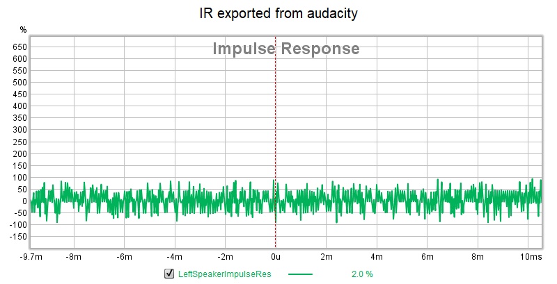
There is the garbage going into DRC.
I import the wav from REW to Audacity, normalize, split stereo, rename tracks to left and right speaker impulse response, export multiple, click OK
after normailization, I can see the impulse peak right in the center at 1 second.
exported format is WAV (microsoft) 32 bit float PCM
I don't see any room to go wrong there but something did. Note also that REW has to ask what the bit rate of the audacity output is. Might be a clue there ...
But I've traced the problem. Stage by stage results are good until I export from Audacity as instructed in the guide.
There is the garbage going into DRC.
I import the wav from REW to Audacity, normalize, split stereo, rename tracks to left and right speaker impulse response, export multiple, click OK
after normailization, I can see the impulse peak right in the center at 1 second.
exported format is WAV (microsoft) 32 bit float PCM
I don't see any room to go wrong there but something did. Note also that REW has to ask what the bit rate of the audacity output is. Might be a clue there ...
Attachments
Awesome work.
Yes those FRs look familiar, same as I see on my workstation
And I do have sub in there, not quite time aligned perhaps. I'm doing XO with sub and pre-eq in miniDSP, at least for now, so I have something to listen to while I'm working my way up the learning curve.
Measurement done out in my 25'x26' garage with car evicted
Lets look at a few other aspects, what did it take to go from one to the other?
Here is the correction file, that DRC generated with my specific template:
As an IR, it looks ugly, but it won't be what you're listening to:
Let's dig a little deeper into what it does for your array,
showing the filtered IR of the RAW IR we've put in:
And how it looks after the correction:

Now remember the advise in the Infinite Line Source theory thread:
Maybe this will shed a light on what I was talking about, how we try and bring the smeared impulse of the array back to a 'Dirac like' pulse within a 20 to 20K window. Which is why I voted for the DRC-FIR treatment.
You've seen my target frequency dependent window, 6 cycles of correction at 20 Hz, almost 12 cycles at 20 KHz and at 2 kHz we have, let's do the math:
113/44100=0.0025 or 2.5 ms which boils down to only 5 cycles of correction applied. In and out with a feather, yet we do get amazing results.
Here is the correction file, that DRC generated with my specific template:
As an IR, it looks ugly, but it won't be what you're listening to:
Let's dig a little deeper into what it does for your array,
showing the filtered IR of the RAW IR we've put in:
And how it looks after the correction:
Now remember the advise in the Infinite Line Source theory thread:
I have a question: can we, at a theoretically fixed listening distance, apply an inverse transfer function to get back to the Dirac pulse at that specific listening distance? Effectively EQ-ing the line back to "flat" response?
In a word, no 🙁 but ... we don't need to 😉
To equalize the impulse response back to a Dirac impulse ... or, alternatively, to equalize back to "flat" frequency response ... would require enormous (essentially, infinite) dynamic range. We have to remember that a truly "impulsive" impulse response corresponds to a frequency response that's flat ... not just over 20kHz, but "from DC to Daylight".
HOWEVER ... we don't need a flat frequency beyond beyond 20kHz 🙂 And there's already plenty of filters in the audio processing chain (below 20Hz, above 20kHz) that will already deviate the impulse response from the idealized Dirac impulse. All we really need from the loudspeaker, is "reasonably flat" frequency response over 20kHz ... and the corresponding impulse response will be just fine 🙂 and that is something that IS possible ...
For example ... recognizing that we probably won't be using a line source in the sub-bass, or maybe even low-bass, regions ... let's say we want to use a line source over the top seven (7) octaves of the human hearing range. The natural frequency response of the Infinite Line Source ... falling at -3dB per octave ... means that we'll need about 20dB of dynamic range to equalize 'flat' over 7 octaves. That's not too crazy, i think ...
Maybe this will shed a light on what I was talking about, how we try and bring the smeared impulse of the array back to a 'Dirac like' pulse within a 20 to 20K window. Which is why I voted for the DRC-FIR treatment.
You've seen my target frequency dependent window, 6 cycles of correction at 20 Hz, almost 12 cycles at 20 KHz and at 2 kHz we have, let's do the math:
113/44100=0.0025 or 2.5 ms which boils down to only 5 cycles of correction applied. In and out with a feather, yet we do get amazing results.
Attachments

Awesome work.
Yes those FRs look familiar, same as I see on my workstation
And I do have sub in there, not quite time aligned perhaps. I'm doing XO with sub and pre-eq in miniDSP, at least for now, so I have something to listen to while I'm working my way up the learning curve.
Measurement done out in my 25'x26' garage with car evicted
That makes a lot of sense 🙂. Not a bad result (as a prediction!) I'd say.
If you have some pré EQ applied to the line, that will be missing from the correction applied as shown in my second post.
I've used variables that were set to do my lines, obviously I don't shoot for a flat target even though that was being used in this demonstration.
I hope this little exercise has got your juices flowing to dive in and learn to 'master' the specifics of DRC-FIR. 🙂
I'll be here to help. The tiny drivers behave quite well in the top end! Without the knowledge of your specific EQ I can't say anything useful about combing, but overall in the prediction it doesn't seem to become a huge problem. It looks better behaved than the TC9 arrays, though without knowing what kind of pré EQ was used we don't see everything just yet.
I bet you're going to have a lot of fun with this setup! I would stay tuned to my mid/side EQ experiments, if you get anything close to this in the actual listening environment it's going to rock!
You can still alter targets, the amount of phase correction applied and stuff like that. Making up your own mind about things like linear phase and whatnot. 😀
Last edited:
I do remember werewolf's advice; I just reread the thread a few days ago. That is pretty convincing compelling proof of DRC's benefits. So I'm eager to get its working at 96000 debugged here.
Low frustration tolerance is more of a problem than intimidation. I never hesitate to jump in.
But I've traced the problem. Stage by stage results are good until I export from Audacity as instructed in the guide.
There is the garbage going into DRC.
I import the wav from REW to Audacity, normalize, split stereo, rename tracks to left and right speaker impulse response, export multiple, click OK
after normailization, I can see the impulse peak right in the center at 1 second.
exported format is WAV (microsoft) 32 bit float PCM
I don't see any room to go wrong there but something did. Note also that REW has to ask what the bit rate of the audacity output is. Might be a clue there ...
The file you've uploaded in post 111 is all you need to play with DRCDesigner. It should work with the 96000 sample rate templates.
I don't quite understand what you were talking about here. All you need is the left IR in PCM format, just like the one you've uploaded.
DRCDesigner probably needs a right side file too, as you still have only one array up and running (I assume), just make a copy of the left for the right impulse and start playing.
The resulting FIR filter can be loaded into JRiver. Pick a template you want to try within that custom tab and make sure you put a file name after that "TCOutFile" parameter to get predictions. You probably need to convert that result from PCM to WAV to be able to read it with REW though.
The wavy line you've shown can simply mean you've picked the wrong type of PCM file.
As input for DRC I use 32-bit IEEE Float (16.8) (mono) but some output files from DRC can have a 32-bit IEEE Float (24,0) format. I don't know why, that's beyond my knowledge of floating point 32-bit files. It's what I see with Cool Edit Pro (and why I love that old trusty tool, the date stamp on it is 2002!).
Last edited:
- Home
- Loudspeakers
- Full Range
- Full range line array for wall or corner placement