posting a starter Vituix model
I would love to see more people embrace simulation.
Attached is a zip of a directory containing all you need to get started simulating once you have installed Vituix. Open the .VXP file in the directory with Vituix and you will see a 25x TC9 array, unshaded and without ground image. The equalization in the model expects the floor and ceiling check boxes in the room tab to be checked.
Good luck and have fun!
Attachments
I tried the same recipe on the unshaded arrays. So 5 heights averaged and used for the correction.
First the model without the ground image:
And with ground image applied:
A bit more wobbly in the higher regions I'd say. Let's compare both curves as corrected:

Some shading may be in my future 😉.
First the model without the ground image:
And with ground image applied:
A bit more wobbly in the higher regions I'd say. Let's compare both curves as corrected:
Some shading may be in my future 😉.
Attachments

"wobbles" I love that term!
The bigger the wobbles the harder it is to EQ them and really they shouldn't be EQed because they are position dependent - we know this because the delta path length is a function of listening distance. Better to reduce them with shading or just ignore them.
The corollary to wobbles being position dependent is that shading out wobbles eliminates the need for that position dependent EQ which should make the response more constant vs distance.
That's why I've always 'corrected' a peaky FIR correction file. Easier had been to measure and average in a few up/down positions.
So far moving away from the correction position (2.7 M) to 3M distance to 3.3M distance seems to hold up pretty good too:
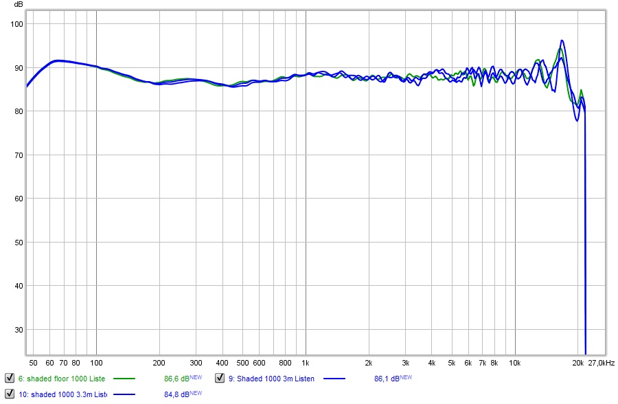
I've corrected for the SPL difference (from moving further away) to see FR plot changes. Quite acceptable.
Unshaded:
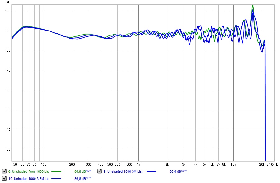
So far moving away from the correction position (2.7 M) to 3M distance to 3.3M distance seems to hold up pretty good too:
I've corrected for the SPL difference (from moving further away) to see FR plot changes. Quite acceptable.
Unshaded:
Attachments

Last edited:
Maybe 🙂 The room is 1 meter narrower in the front than in the back. Also, roof is 1 meter higher in back than front. Thats the plan. How do I simulate this?
//
//
Last edited:
If the arrays are at the front side, that would make them a CBT with the ceiling mirror image 😀.
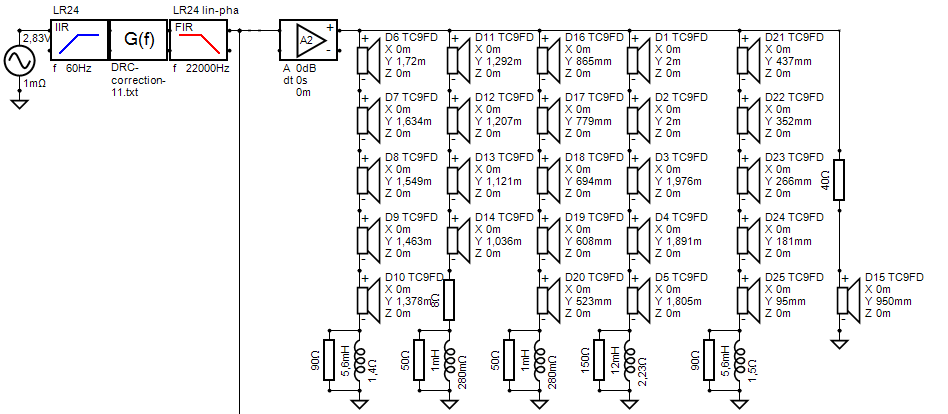
My shading schematic (the base for this was one of nc535's schematics with floor image, I adjusted it to meet my specific driver positions)
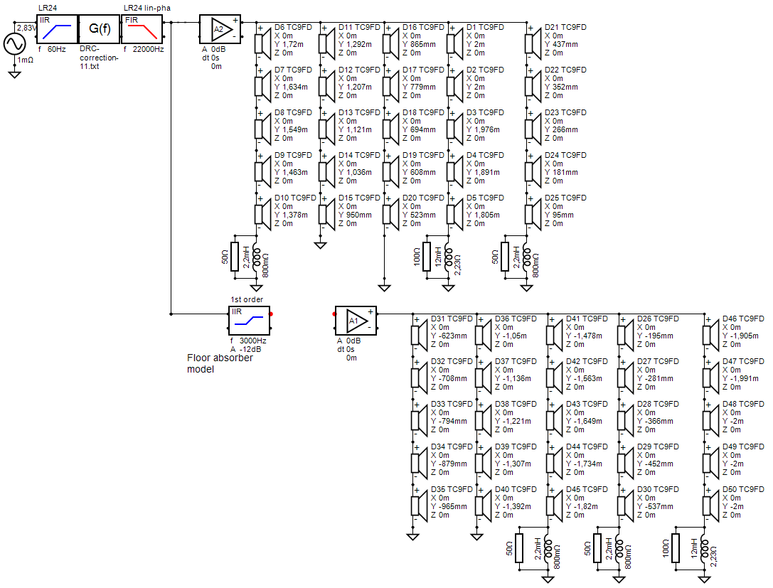
I haven't looked up the resistors yet, but the inductors can be had (even in air core) for not a lot of money. I found a few Jantzen Air Core that would fit the bill.
I may try and improve on this, but my main goal is to keep what I have that's regarded as a positive (good balance in sitting and standing positions).
I've looked at it from all angles I could think of and come to a preliminary conclusion that chasing this could very well be worth the trouble.
That is, without going all out with a super DSP aligned solution. I don't see myself moving in that direction. This is a relatively simple solution with potential. More simming could lead to even better solutions.
(I've done 12 so far! 😱)
I'm using DRC to do the corrections, exporting what I need to REW, average them and run DRC on it with one of my templates.
Then I convolve the pré-EQ with the DRC correction and export it as txt to apply it to the Virtuix model.
Attachments

Last edited:
The bigger the wobbles the harder it is to EQ them and really they shouldn't be EQed because they are position dependent - we know this because the delta path length is a function of listening distance. Better to reduce them with shading or just ignore them.
That's why I've always 'corrected' a peaky FIR correction file.
I don't disagree in principal, but in practice the best result I have achieved corrects the comb pattern at the listening position through the use of a longer upper window. I have tried various different schemes to reduce this "over correction" but none of them are actually better so far than letting it be over corrected. Not ready to draw any real conclusion other than I know which one I like better when I hear it.
If there is a simple shading scheme that doesn't reduce output but helps reduce combing I could be persuaded to try that 🙂
That thread is where the track of increasing driver size as one moves away from center leads
I do not think it is only about that, at least their objective seems to be similar to yours. I learn from both, so I am happy 🙂
I don't disagree in principal, but in practice the best result I have achieved corrects the comb pattern at the listening position through the use of a longer upper window. I have tried various different schemes to reduce this "over correction" but none of them are actually better so far than letting it be over corrected. Not ready to draw any real conclusion other than I know which one I like better when I hear it.
If there is a simple shading scheme that doesn't reduce output but helps reduce combing I could be persuaded to try that 🙂
I can't deny that I do have had a similar experience, if I look back at single seat corrections. I have had a knock out of the park single seat correction that I can't quite match with multipoint correction (horizontal averaging).
However I kept the multipoint correction in place because it did perform better overall in the room.
I've never quite got the same results back in that single seat, it was scary good. However I do hope that this shading is going to change that (for the better), so far the predictions show me it could be the way forward.
It is completely reversible... should it not bring what I hope. Just a lot of work. I do believe this scheme does not reduce output anywhere, the same amount of drivers runs at lower frequencies. Improvement in the upper frequencies is obvious, you could make a killer correction at a single position with this in place, but the up/down movements would be limited. However I like what I see as far as early waterfall plots go.
If I look at the sims, I ran the unshaded one 1 dB hotter, but looking at the filter window in both sims the 10 center drivers run with a similar amount of boost as the unshaded 25 drivers. That means they do have to work a little harder. I expect real world results will be a bit better at the top end, also based on your outside measurement but cannot count on that. I'll try and match SPL in both and adjust and compare.
Wesayso, don’t think we can call that shading. It’s an expanding array, no? Great sims, btw.
It does come close to an expanding array but not quite. I do use 6 dB (resistor bypassed with an inductor) shading for the first two groups and 12 dB for the upper outer group. I plan to sim a complete expanding array with a single top end driver, still using this high shelf attenuation scheme. I can't predict the outcome, the sim will tell the story. 🙂
I've 'only' done 12 sims so far... showing one... It costs nothing but time.
Last edited:
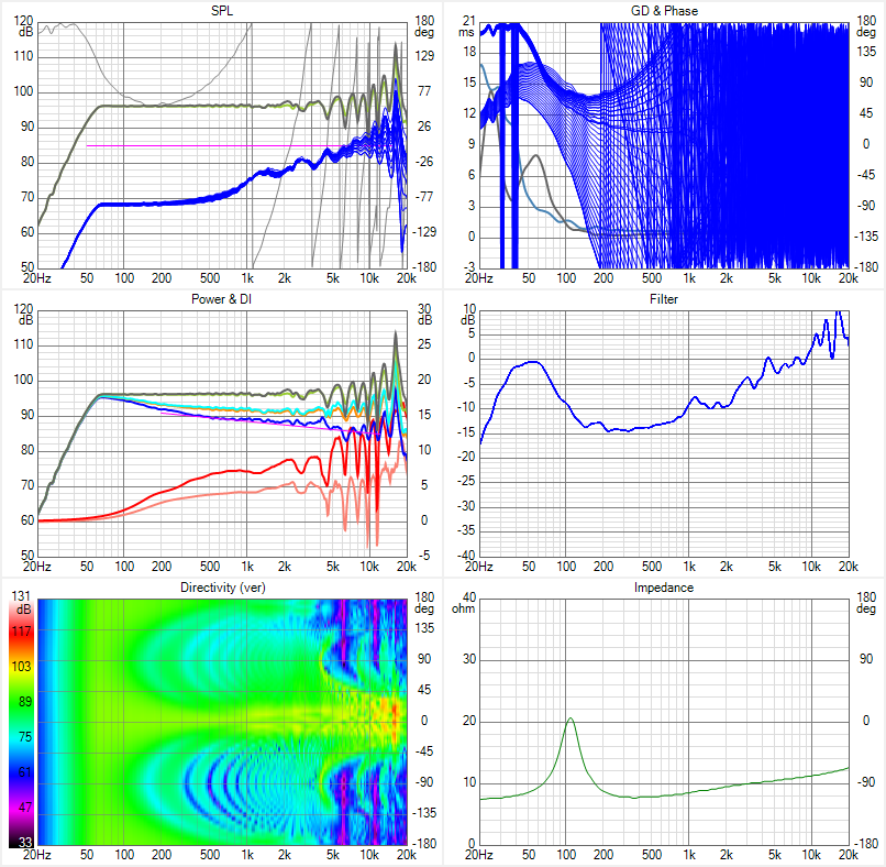
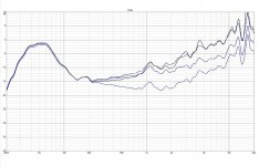
Adjusted SPL to match, and overlaid both SPL and Filter graphs...
First the SPL graphs:

(Unshaded measurements are in grey)
And next the Filter graphs:
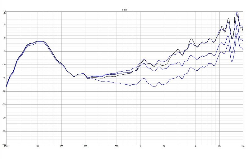
It seems the top correction is about similar, but shared among less drivers.
The peaks in the Unshaded version are higher, without it getting a flatter correction as a result, it may sound louder though, due to the peaks.
Bottom end is practically the same, with all drivers sharing the load. The top 5 filtered drivers fall back about 1 dB due to the 2.23 ohm resistance of the air coil inductor. The other 10 filtered drivers can be seen lagging less than half a dB, due to a 0.8 ohm air coil inductor.
So all in all, we do get better upper performance but they will be working a bit harder with 10 vs 25 drivers playing the upper end. Bottom end is a tie.
I'm guessing real world results may and will differ somewhat.
First the SPL graphs:
(Unshaded measurements are in grey)
And next the Filter graphs:
It seems the top correction is about similar, but shared among less drivers.
The peaks in the Unshaded version are higher, without it getting a flatter correction as a result, it may sound louder though, due to the peaks.
Bottom end is practically the same, with all drivers sharing the load. The top 5 filtered drivers fall back about 1 dB due to the 2.23 ohm resistance of the air coil inductor. The other 10 filtered drivers can be seen lagging less than half a dB, due to a 0.8 ohm air coil inductor.
So all in all, we do get better upper performance but they will be working a bit harder with 10 vs 25 drivers playing the upper end. Bottom end is a tie.
I'm guessing real world results may and will differ somewhat.
Attachments

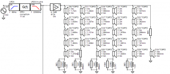
Teaser for the expanding array, isolating one driver for the top end.
No time to finish simulations, just a raw sketchup.
Need to finetune the resistors and inductors and the sole driver will need compensation for the impedance peak, a simple resistor isn't cutting it.
Sole driver is at listening level, 100mm, I know it says 950mm because the floor level in this model actually is -50mm where the mirror line is for the
simulated mirror drivers. (long story)
Attachments
W's shading doesn't cost any output at the low end, just at the high end, where I believe there is margin with a driver with a rising response like the TC9. Lessening the contributions from the most distant drivers is key to reducing combing ripple so that it doesn't need to be equalized. If the best sound is heard when that ripple is equalized, it should be better or as good over a wider area if shading reduces the amount of EQ needed.
Its interesting to note that a resistor in series with drivers provides a degree of frequency dependent shading by itself due to the impedance peak at resonance.
In the expanding array where a single driver is responsible for the entire top end, I'm concerned about SPL/robustness. I would prefer to use something like an SB26 tweeter that has over 90 db sensitivity and can handle 100W. To control its directivity, I would put it in an OS waveguide with mouth size matching TC9. That might do the trick. The other thing to try is to allow more drivers to contribute up top based on delta path length rather than fraction of wavelength spacing on baffle.
I tried importing Augerpro's tweeter in waveguide directivity. I needed finer steps and more than just out to 60 degrees. I will see what I can get from HR for a single OS profile.
If I were to do this last schematic (not saying I will) I would opt for a 10F as the central tweeter. Shave it's basket and it is a drop in replacement. And I'd shave off the entire bottom end having it play from ~200 Hz and up.
It is more efficient than the TC9 and has a better top end as well (before EQ).
Just fooling around, really. A bit curious how far one could go with this.
It is more efficient than the TC9 and has a better top end as well (before EQ).
Just fooling around, really. A bit curious how far one could go with this.
.
Just fooling around, really. A bit curious how far one could go with this.
I may have an example of too far soon 🙂
I see 🙂, just made a rough example correction and it's not a winner...
Excellent performance at the sweet spot, but the up/down measurements don't look better than what I had.
Move back and it kind of falls apart too.
Excellent performance at the sweet spot, but the up/down measurements don't look better than what I had.
Move back and it kind of falls apart too.
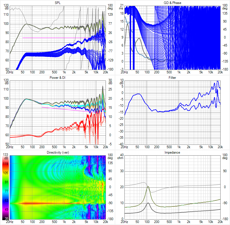
In the spirit of climbing a mountain because it is there, I pursued the central waveguided tweeter idea with a modicum of success. I modeled a 3/4" OS profile 3.5" high in HR response than exported 5 degree steps of directivity one step at a time for use in Vituix. After EQ, this produced the directivity on the top left image below.
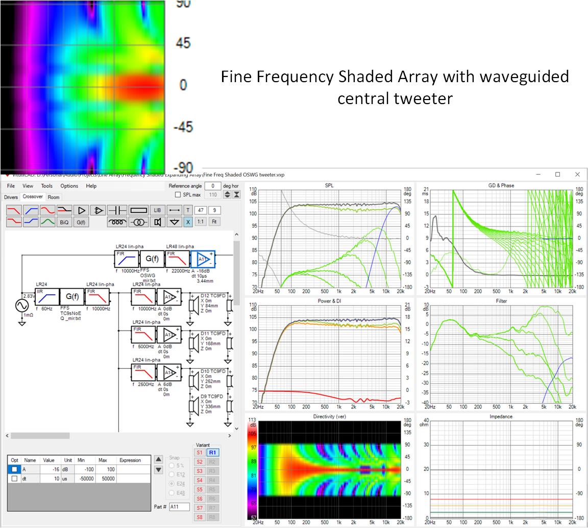
I then optimized my fine frequency shaded array to graft it on. It turned out I needed relatively steep slopes in the TC9 filters to prevent subtractive contributions from them from pulling down the high treble. And then I had to allow the lowest two groups of drivers to contribute all the way up to 1000 and 500 Hz respectively to prevent floor and ceiling boundary dips and nulls in the mid bass.
This array has a usable vertical window of at least +/- 400 mm at 3m listening distance but it is a waveguided point source at the center of an array so the balance between the tweeter and the rest degrades with distance due to 3db vs 6 db per doubling of distance. The benefit of the full line vs the H-K approach is the vertical directivity can be extended low enough to avoid ceiling modes.
While this looks pretty good, I suspect one could do as well or better with Horbach-Keele crossovers and perhaps 3 pairs of successively larger drivers flanking the central waveguide/tweeter.
Attachments

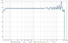
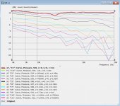
I have a non commercial licence for VACS the output viewer for ABEC/AKABAK and I can (somewhat laboriously) export the directivity curves from the horn simulations. Without some significant tinkering the simulation is based on an infinite baffle, but I think it could be useful.I tried importing Augerpro's tweeter in waveguide directivity. I needed finer steps and more than just out to 60 degrees. I will see what I can get from HR for a single OS profile.
As an example this is the VACS output (8k to 20K simulated)
And this is exported text files of the top two curves imported into REW.
This might be a good way to use the speed of Vituix with some of ABEC's power.
Joseph Crowe has an interesting speaker design that touches on some this, the Nighthawk.
The waveguide in the centre or something similar could be designed to fit in the centre of the line with whatever directivity was needed to match and that part of the design seems to work well in the 3K plus range with a compression driver (ND350) which should be more than enough to cover the problematic areas being discussed.
I understand the potential issue of the falloff with distance being different from a line source rather than a point source, I wonder if this is a good candidate for simulating to see how it might work given that most listen and EQ at a specific distance.
This reminds me a picture wesayso has posted a few times of a big waveguide in a line of large woofers except on a slimmer scale.
Attachments

- Home
- Loudspeakers
- Full Range
- Full range line array for wall or corner placement