The Nighthawk will no doubt sound better than it looks🙂 I guess that is an example of what it takes to control directivity all the way down. We here realize however that a little padding on the walls eliminates the need for so much control The waveguide in the middle remains interesting. Mabat has made it much easier for us to study and implement them. I was getting ready to do some of that when I got distracted by these line array simulations.
I used up all the time I had getting as far as I did. I will do the sims vs height and distance for yesterday's array today. The 3db vs 6db issue is not problematic for where I would want to use such a speaker.
Going further, there is the question of what size waveguide for the center. Most times the answer to array size is as big as you can stand but that is because you can't get vertical control from a wavequide alone without size. I would hope to match widths with perhaps 6.5" woofers. I still have a pair of SEOS12's around somewhere though; wasn't there a SEOS8 that was used with a tweeter?
Ah.. the BD-Design waveguided array...
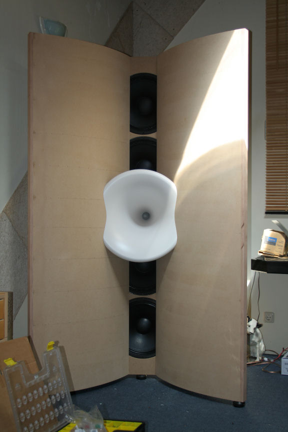
The concept still exist, but he cut the line in half:
BD-Design, only the best!
And it seems he's now using a full range driver for the waveguide 😉.
The concept still exist, but he cut the line in half:
BD-Design, only the best!
And it seems he's now using a full range driver for the waveguide 😉.
Attachments
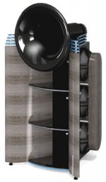

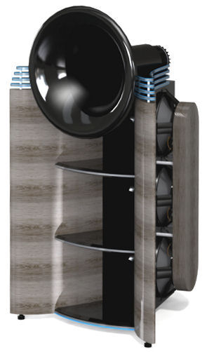
Nice examples; getting well up into the as big as one can stand range. BTW, the big as you can stand quote comes from John of AE Speakers as the recommended box size for one of his woofers.
The nice thing with those examples is they match horizontal directivity with the woofers. Without such wings, the waveguide width needs to match the woofer width which is why I started with 3.5".
Pretty and no doubt as effective as those are, I don't want to go there. I went to line arrays to get away from large waveguides; not because I don't like them but because I despaired of being able to make room for them.

Nice examples; getting well up into the as big as one can stand range. BTW, the big as you can stand quote comes from John of AE Speakers as the recommended box size for one of his woofers.
The nice thing with those examples is they match horizontal directivity with the woofers. Without such wings, the waveguide width needs to match the woofer width which is why I started with 3.5".
Pretty and no doubt as effective as those are, I don't want to go there. I went to line arrays to get away from large waveguides; not because I don't like them but because I despaired of being able to make room for them.
Personally, I don't believe we have to. From these sims here, it is clear we can improve upon the full unshaded line, leaving the top end a little behind maybe. But it doesn't even have to be that far behind.
I think some shading really is in my future, but also a little change in processing. The processing based on an average vector sum is all nice and dandy but doesn't work that well in the top end. It does not help out the top end and is responsible for bigger peaks/valleys than it should be.
I'm willing to process the FR curve in the exact single point sweet spot (maybe even at true ear positions) while adjusting its overall FR response to match an average of multiple measurement positions. If all goes well it should bring good tonality to a wide area (reason for me to use averages in the first place) while having excellent properties in the sweet spot.
I still need to work out how to do it exactly, but I bet this would improve on my current results. The wobble as I called it is almost cut in half with the shading I applied in that sim, the top end would improve with the above suggested processing method and overall it would still bring great 'in room' performance.
What I have right now does quite well over a wide area, if I can get back what I have had/heard in the sweet spot it would be all I could ever wish for. But that's just my planned route forward.
Investigate what happens at ear positions in a Stereo listening situation and you'll come to realise you do not need complete 'wobble free' performance over a wide area at the highest frequencies. That's simply not the ticket, at least not by itself. I'd accept plus/minus 2 dB on the very top end as long as it is even over a wider area. Tonality will hold up.
One of the various techniques, either mid/side EQ, a variation of the shuffler or a simplified version of cross-talk cancelation or a combination of these techniques can finish it off for 'really great' performance.
I don't believe we need a tweeter and the complications it brings. At least I won't be searching for a solution like that. I'll gladly accept the prior sim I did using 10 drivers full range and move on from there with more clever processing. I don't need it to be perfect standing up. Just "right" tonally. Not deviating too much from other positions. I need it to be very good at seated positions and wider horizontally, while keeping tonality in check in the room.
A pleasant sound in the house, excellent performance in the sweet spot. That would be my ideal compromise. I've come close but not quite there. Every bit of performance gain would be welcome to get a little closer.
I would not do this without mid/side processing or a variation thereof and the absorption panels + ambient speakers. That I can say.
Pick your own poison, but the above is where my focus will be. It will take me quite a while to get there though. But i'm not in a hurry.
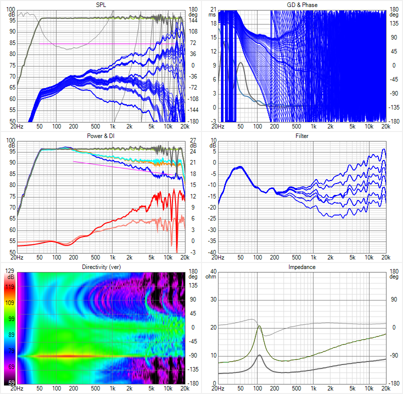
I went to take data vs vertical mic offset and found the window to be smaller than I thought I had seen yesterday. The cause was a growing dip at the 10 khz XO to the tweeter. I lowered that XO to 6 khz and got these data:
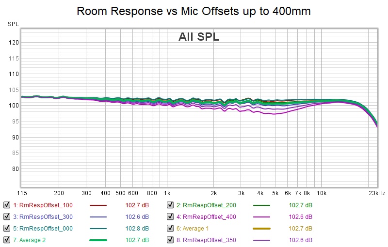
I still have a dip at the XO but its not severe. The equalization was done at array center and is down worst case 4.5 db at the bottom of the dip at 400 mm offset. Equalizing to the average of those heights should make the entire 800 mm window usable.
I still have a dip at the XO but its not severe. The equalization was done at array center and is down worst case 4.5 db at the bottom of the dip at 400 mm offset. Equalizing to the average of those heights should make the entire 800 mm window usable.
Attachments
That's where I would prefer the wobble. As long as those are centered around the middle line they will keep it sounding balanced. I think you hear a sagging result over a wide area like this, sooner than a sight up/down variation that stays close to the center line. (as much above as it is below it)
What does this do moving half a meter closer or further away?
What does this do moving half a meter closer or further away?
(still climbing that mountain because its there but its beginning to look like it might be worth the effort)
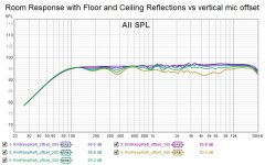
Here is the response vs listening distance. I first looked at this without floor and ceiling reflections enable, which is how it was equalized and how it has to be to get mic offset data, and I saw almost no variation with distance. Then I recalled that the floor and ceiling bass support does vary with distance so I enabled the reflections and got this data:
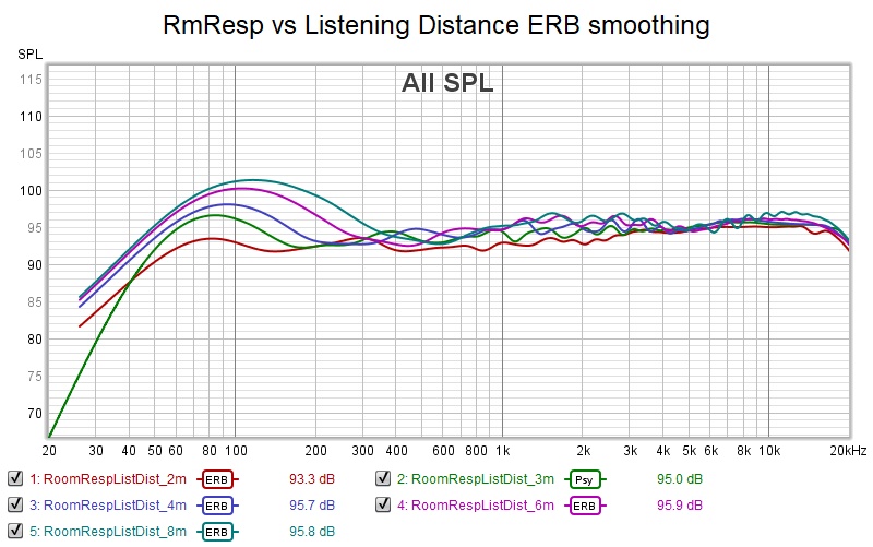
ERB smoothing was used to mask the comb lines that are caused by the longer delayed ceiling and floor reflections and which would otherwise obscure the data
Here is the response vs listening distance. I first looked at this without floor and ceiling reflections enable, which is how it was equalized and how it has to be to get mic offset data, and I saw almost no variation with distance. Then I recalled that the floor and ceiling bass support does vary with distance so I enabled the reflections and got this data:
ERB smoothing was used to mask the comb lines that are caused by the longer delayed ceiling and floor reflections and which would otherwise obscure the data
Attachments

The tendency is there. As you move further away, the delta path length reduces, so the destructive combining reduces so you should get more treble. As you move up or down, you move off the center of the vertical beam and thus get less treble.
A pleasant sound in the house, excellent performance in the sweet spot
well said, my goal as well. In addition and I'm sure you agree, make that sweet spot wide enough for 2 or 3.
Kimmosto just made some changes at my request
Main program
* Microphone offset group in Room tab renamed to Driver offset. Location of all driver instances in crossover can be changed temporarily by X,Y mm.
* Added Relocate button to Driver offset group in Room tab. Location of all driver instances in crossover are changed permanently by X,Y mm.
* Enabled reflection simulation simultaneously with driver offset.
* Parameters in Room tab saved to project file.
* Max 75 drivers can be added at once with Driver layout window.
* Initial Y Min/Max of driver component increased to -2500/+2500 mm.
* Y scale of Driver layout graphs expanded to -2500...+2500 mm.
* Drivers added with Driver layout window are located to crossover schematic on the right side of existing drivers
Thanks, Kimmosto
We'll soon see if I should have been more careful as to what I asked for 🙂
with 75 drivers we can get another set of image drivers but with ability to do driver offset with reflections enabled, we may not need to, except to model absorption separately for different surfaces and with frequency dependence
I think I blew it on the baffle height; should have asked for just over 6m total height
.
The tendency is there. As you move further away, the delta path length reduces, so the destructive combining reduces so you should get more treble. As you move up or down, you move off the center of the vertical beam and thus get less treble.
You called it!. I doubled distance to 6m and moved up 400mm, no floor or ceiling reflections other wise would bass wouldn't be flat
Attachments
Kimmosto just made some changes at my request
Main program
* Microphone offset group in Room tab renamed to Driver offset. Location of all driver instances in crossover can be changed temporarily by X,Y mm.
* Added Relocate button to Driver offset group in Room tab. Location of all driver instances in crossover are changed permanently by X,Y mm.
* Enabled reflection simulation simultaneously with driver offset.
* Parameters in Room tab saved to project file.
* Max 75 drivers can be added at once with Driver layout window.
* Initial Y Min/Max of driver component increased to -2500/+2500 mm.
* Y scale of Driver layout graphs expanded to -2500...+2500 mm.
* Drivers added with Driver layout window are located to crossover schematic on the right side of existing drivers
Thanks, Kimmosto
We'll soon see if I should have been more careful as to what I asked for 🙂
with 75 drivers we can get another set of image drivers but with ability to do driver offset with reflections enabled, we may not need to, except to model absorption separately for different surfaces and with frequency dependence
I think I blew it on the baffle height; should have asked for just over 6m total height
.
Yes, it's fun to have the drivers available, but without the height... we still can't sim the ceiling...
But as said, maybe we don't need to. If we can use the functions for ceiling and floor while placing the mic where we want it.
With the new release of Vituix, I can response vs mic height with floor and ceiling reflections:
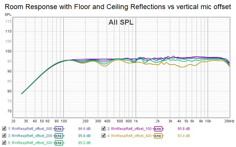
The gold trace for 400 mm offset is over the threshold into un-usability. But the smaller offsets are impressively flat.
The gold trace for 400 mm offset is over the threshold into un-usability. But the smaller offsets are impressively flat.
Attachments
I redid my processing from the shelf-shaded array I did earlier, processing with floor image on. That's the one with the 10 unshaded drivers around the listening spot/height.
I also made a pure center correction, to see the differences between those two. As said earlier the vector average isn't a good representative for the top end of the array.
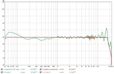
A quick comparison in SPL:
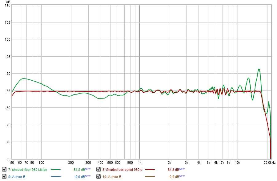
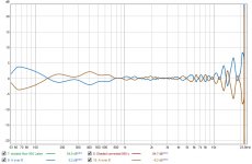
And if we extract them from each other, purely using the SPL levels we get this:
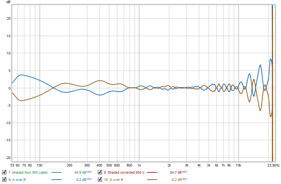
Subtracted either way to exaggerate the differences. As seen the top end is quite different between the center correction and the faulty average vector sum.
If we look at that the difference in waterfall results are clear too:
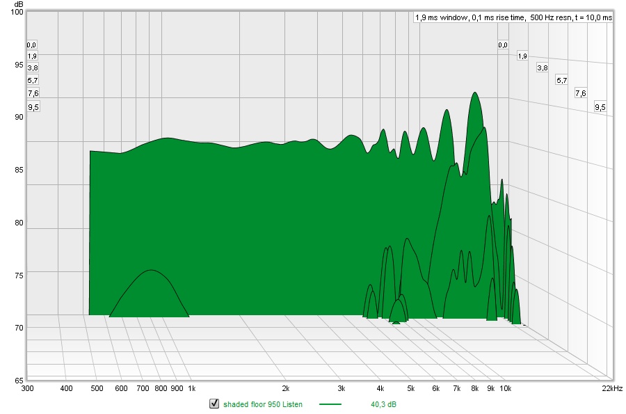
Average based processing...
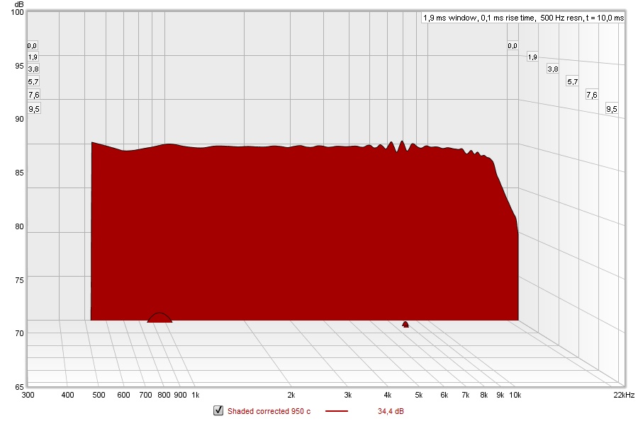
Center listening position processing...
You might hear a difference between the two. It might be a bigger change than the SPL change between 700 Hz and 10 KHz predicts...
I'll repeat this test for an unshaded array, as the above result of the shelf-shaded array makes me quite comfortable to move back to a center position measurement correction. As long as the horizontal positions work too (which has never been a huge problem with the arrays).
I also made a pure center correction, to see the differences between those two. As said earlier the vector average isn't a good representative for the top end of the array.
A quick comparison in SPL:
And if we extract them from each other, purely using the SPL levels we get this:
Subtracted either way to exaggerate the differences. As seen the top end is quite different between the center correction and the faulty average vector sum.
If we look at that the difference in waterfall results are clear too:
Average based processing...
Center listening position processing...
You might hear a difference between the two. It might be a bigger change than the SPL change between 700 Hz and 10 KHz predicts...
I'll repeat this test for an unshaded array, as the above result of the shelf-shaded array makes me quite comfortable to move back to a center position measurement correction. As long as the horizontal positions work too (which has never been a huge problem with the arrays).
Attachments


Last edited:
Green looks like a mountain stage of the Tour de France. Red is the obvious choice, there is no comparison. The reason you say one only might hear a difference is understatement or acknowledging smoothing implicit in hearing?
Certainly an understatement 🙂. There is a difference in perception between imaging and tonality. While the wild graph can still provide decent tonality, the green one will have the better shot at good or maybe excellent imaging.
So for my central position I'd like the green graph, while keeping the balance in the area around that spot good enough for tonality.
I'll sim the unshaded array in a similar fashion and that could provide more information if shelf shading can be used as a performance upgrade on these arrays.
I think it would/could. Which would allow me to use one spot correction while being more than acceptable in performance over a (much) wider area.
Maybe I should upgrade to the new Virtuixcad to add the ceiling added to the game.
Next up will be to fine tune where and how much shelving is needed to be able to shape all positions of interest. The ambience speakers will help out to keep tonality in check below 3K, while also playing a role in imaging. The bottom end has never been a problem, certainly not with subbs added while using the arrays there too. (they are a lot of fun when combined)
It seems we can somewhat shape the bundle we need. Improving the top end while keeping the up-sides of using multiple drivers.
Right now moving down shows excellent tracking of the center line target, while moving up still is a somewhat bigger change (wobble 😉) between 2 and 5 KHz. No doubt the ceiling reflection would help somewhat. As did the floor. But I might need to fine tune the shelf shading.
Attachments

Last edited:
- Home
- Loudspeakers
- Full Range
- Full range line array for wall or corner placement