🙂 🙂 re multi-channel active. I had 8 channels going with my synergies and subs but that was 8 channels of IIR in a MiniDSP 8x10 with JRiver FIR for global EQ. That wasn't bad but 8 channels of FIR in Jriver scares me.
Its hard to imagine Purifi not being good enough. I"ve never seen better specs on a class D amp. Class AB I'm not sure but my back isn't strong enough for old school class AB.
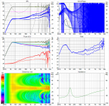
Yes Vituix does indeed predict the -3db per octave but you won't see it in every picture because the first thing I do is EQ it away. Look at the filter curves in middle right graph of those sets of 6 Vituix graphs. You'll see how much filter gain is needed to flatten the treble, among other things.
Vituix also will show the expected bass boost when you include a set of ground image drivers in the crossover schematic or when you enable floor and ceiling reflections in its room response tab.
Vituix breaks though when I include both floor and ceiling image drivers; in fact it cracks a little with just ground image drivers. Its limited to 64 drivers and a +2m to -2m tall baffle and near those limits it gets a little sluggish.
Its hard to imagine Purifi not being good enough. I"ve never seen better specs on a class D amp. Class AB I'm not sure but my back isn't strong enough for old school class AB.
Yes Vituix does indeed predict the -3db per octave but you won't see it in every picture because the first thing I do is EQ it away. Look at the filter curves in middle right graph of those sets of 6 Vituix graphs. You'll see how much filter gain is needed to flatten the treble, among other things.
Vituix also will show the expected bass boost when you include a set of ground image drivers in the crossover schematic or when you enable floor and ceiling reflections in its room response tab.
Vituix breaks though when I include both floor and ceiling image drivers; in fact it cracks a little with just ground image drivers. Its limited to 64 drivers and a +2m to -2m tall baffle and near those limits it gets a little sluggish.
The thread has become quite long, so I may have missed it. Have you simulated some "capacitive shading", like applied in this project?
Bauanleitung | Visaton
I reckon it is only 6dB/octave, but probably much simpler.
Sorry, busy day, I only just got back to your post and the link in it.
I haven't tried anything like that. I'm not sure I would call that shading although its a very elementary form of it. But then such a short line might not need much shading. I've been using inductors to block high frequencies whereas that designer used capacitor to bypass high frequencies around some drivers. Good idea I suppose as C's are cheaper than L's . I hate to say it but FIR filters in this particular case do produce better results for their higher cost but you would never know it without simulation. As I can see from the feedback here, everyone's first instinct is to try to do with passive components.
Multi channel FIR convolution in Jriver isn't that scary, just need to get your head around the configuration text file needed. Getting the grounding right can be somewhat of a headache. This is an occasion where balanced input amps are really useful.🙂 🙂 re multi-channel active. I had 8 channels going with my synergies and subs but that was 8 channels of IIR in a MiniDSP 8x10 with JRiver FIR for global EQ. That wasn't bad but 8 channels of FIR in Jriver scares me.
I thought the same about UcD and there ended up being something about them I couldn't live with for mid and high frequencies. Others have reported similar things with Ncore so improved measurements are not necessarily a solution to that issue. I'm still tempted though so maybe I will find out 🙂 I really liked the LM3886 chip amps I had in an 8 channel setup for Orion, I suspect something like Tom's LM3886 Done Right might work if the boards were cheaper. I have also had good results with modern SMPS power supplies designed for Audio, no weight issues there but reasonable PSRR is needed.Its hard to imagine Purifi not being good enough. I"ve never seen better specs on a class D amp. Class AB I'm not sure but my back isn't strong enough for old school class AB.
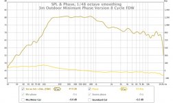
It was more where that ends and the shelf begins, like this outdoor measurementYes Vituix does indeed predict the -3db per octave but you won't see it in every picture because the first thing I do is EQ it away.
Attachments
Sorry, busy day, I only just got back to your post and the link in it.
I haven't tried anything like that. I'm not sure I would call that shading although its a very elementary form of it. But then such a short line might not need much shading. I've been using inductors to block high frequencies whereas that designer used capacitor to bypass high frequencies around some drivers. Good idea I suppose as C's are cheaper than L's . I hate to say it but FIR filters in this particular case do produce better results for their higher cost but you would never know it without simulation. As I can see from the feedback here, everyone's first instinct is to try to do with passive components.
I believe you right away that the FIRs and multiamplification will do better then simple 1st order "capacitor filters". I was just curious about the compromises.
Another question: in post 512 you wrote
Yes, smaller drivers would help get a wider response and you really just need them in the center. MTMing the center triplet gets some control of the vertical directivity.
So, as we are already wandering away from the TC9 for the center triplet, would there be a problem using 2x 168mm drivers (2x 84mm height of TC9) for the 4th group (the one with LP at 375Hz) and some 336mm drivers (4x 84mm height of the TC9) for the 5th and 6th group? For the required frequency range these bigger drivers would be suitable and provide more low end, but I do not know which enclosure you are using for the simulations, so I do not know if these drivers would fit.
Many thanks for the simulations and your extensive reactions, I am learning a lot!
changing drivers with height will indeed complicate the enclosure and require an entirely new design from the ground up but the benefit will indeed be more bass.
And using a smaller driver in the center is not completely straightforward. That smaller driver works alone over the entire upper midrange and treble - so it must be highly efficient or have high power handling but it can't have too wide a dispersion. I'm still looking for the right driver. TC9 at 83 db sensitivity and 30W is sufficient the 1.5" DMA45 at 82 db and 10W is marginal. A robust tweeter like the SB26 has more than enough SPL but too much dispersion for an easy directivity match.
And using a smaller driver in the center is not completely straightforward. That smaller driver works alone over the entire upper midrange and treble - so it must be highly efficient or have high power handling but it can't have too wide a dispersion. I'm still looking for the right driver. TC9 at 83 db sensitivity and 30W is sufficient the 1.5" DMA45 at 82 db and 10W is marginal. A robust tweeter like the SB26 has more than enough SPL but too much dispersion for an easy directivity match.
Thanks for the reply. I may have been mixing ideas with things I read in this thread
https://www.diyaudio.com/forums/mul...led-directivity-loudspeakers.html#post6140927
keep up the excellent work!
https://www.diyaudio.com/forums/mul...led-directivity-loudspeakers.html#post6140927
keep up the excellent work!
Yes, its managing that config file that concerns me. Can I embed comments in it? What delimiter?Multi channel FIR convolution in Jriver isn't that scary, just need to get your head around the configuration text file needed. Getting the grounding right can be somewhat of a headache. This is an occasion where balanced input amps are really useful.
That is good to know. Thanks for sharing! Maybe I should try an Ebay LM3886 board and hope I get lucky!I thought the same about UcD and there ended up being something about them I couldn't live with for mid and high frequencies. Others have reported similar things with Ncore so improved measurements are not necessarily a solution to that issue. I'm still tempted though so maybe I will find out 🙂 I really liked the LM3886 chip amps I had in an 8 channel setup for Orion, I suspect something like Tom's LM3886 Done Right might work if the boards were cheaper. I have also had good results with modern SMPS power supplies designed for Audio, no weight issues there but reasonable PSRR is needed.
It was more where that ends and the shelf begins, like this outdoor measurement
Nice measurement! Eliminating the room really cleans things up.
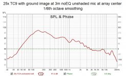
Here is the equivalent from Vituix. Its similar but not the same. Combing appears exaggerated in the sim for one thing but smoothed out here. REW won't let me FDW an imported test file so I smoothed it 1/6 octave. The sim drops further with frequency.
A big difference may be that the sim sums outputs from 25 identical drivers whereas the measurement sums and thereby averages outputs from 25 drivers with a random spread of response around the data sheet response
Attachments
Thanks for the reply. I may have been mixing ideas with things I read in this thread
https://www.diyaudio.com/forums/mul...led-directivity-loudspeakers.html#post6140927
That thread is where the track of increasing driver size as one moves away from center leads
What I meant is the effective line length. Say you have a 2m tall line. If its on a perfectly reflective floor ( a ground plane). The ground reflection, which I model with a set of mirror image drivers, doubles its effective length to 4m. Then there is also the ceiling reflection. With that added to the ground image, the effective length is tripled. Consider what happens with true sound mirrors for floor and ceiling: even the reflections have reflections. That is how one gets to the infinite length model. But you can't get there because of imperfect reflection and driver directivity. Its really hard to know what the effective length of an array in a particular room is; its usually going to be long enough that vertical directivity extends low enough to eliminate floor and ceiling bounce nulls but not long enough that response is invariant vs height. Its best to have a thin layer of absorber on floor (carpet) and ceiling (ceiling tile) to absorb instead of reflect starting at several khz.
By continuous line I meant exactly that, what you get from a ribbon or planar. A discrete line approximates a continuous line, at least at LF and MF. That approximation begins to break down at 1/4 wave spacing and is completely gone by 2 wavelength spacing.
The reason I drew the distinction was to emphasize that the effects of being finite instead of infinite are different than the effects of being discrete vs continuous.
Thanks for reference to the book. I will have to get a copy
Yes, I think we are saying the same things, and with a good grasp of infinite line theory, as well as the practical limitations.
It's cool you are taking the simulation steps to explore how real-world length and spacing vary from theory.
If you'll remember, I want to experiment with a room that has a concrete floor and ceiling....that's my way of getting the best mirror to extend the line ...haha...
I think your way of simming might be a cheaper way of experimenting lol
on multi channel FIR for shading experiments....
i used 8 ch of minidsp for a while, as well as 8 ch of JRiver with config file.
The minidsp was harder for me to keep track of simply due to the number of separate FIR file names.
I don't remember if notes could be put in the JRiver config file implementations, but i do remember i could name the overall file in ways that made more sense that all the discrete minidsp names.
(I had to beg minidsp for years to store FIR file names in the files for identification....but i believe that is fixed (opendrc for certain, you should double check for DA-8))
No doubt re' saying the same things but the more details I learn via simulation the more I feel compelled to speak precisely.
After all these sims, I think the best way to sim is to use the room response tab with floor and ceiling reflections enabled and use the orange room response curve as the equalization reference. This forces you to take your output from array center as opposed to ear height from the floor but it makes the simulation easier and less painless. I'm sure its true to a fair extent at least that if you can get a good response at array center, you can also get a good one at ear height, line array theory says so. As a final step you can try to create a model with floor and ceiling images and contend with Vituix limits (which I've asked Kimmosto to extend) and slow-responding simulation user interaction to predict response at target ear height.
Yes, I find long, descriptive directory, file and variable names and a consistent project directory structure to be indispensable. I just wish I were better at practicing what I just preached.
Then you will need TNT to remodel it
😀😀😀😀😀😀 Too funny 🙂
Which is exactly why it ain't gonna happen !!!!!!
I'm joining the simulation fun (thanks to nc535) but I'm looking for other things 🙂.
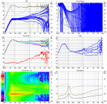
How do I keep the widest sweet spot possible while improving on an unshaded array. Here's a careful first result done with DRC-FIR and using averages of 4 different heights as the base for processing. No floor/ceiling image used here.

Standing will still get quite a reasonable listening curve.
Shading the bottom 5 by about 6 dB with a resistor and inductor, followed by 10 drivers unshaded, next group is again shaded ~6 dB with resistor bypassed by an inductor. Top 5 drivers cut off earlier.
The goal wasn't to avoid all combing here. but to possibly get better results with (simple) shading used on the drivers furthest from listening axis. Now I just need to repeat the whole process for an unshaded array. Heights, driver distances etc. are an exact copy of my array.
With floor image drivers active:

How do I keep the widest sweet spot possible while improving on an unshaded array. Here's a careful first result done with DRC-FIR and using averages of 4 different heights as the base for processing. No floor/ceiling image used here.
Standing will still get quite a reasonable listening curve.
Shading the bottom 5 by about 6 dB with a resistor and inductor, followed by 10 drivers unshaded, next group is again shaded ~6 dB with resistor bypassed by an inductor. Top 5 drivers cut off earlier.
The goal wasn't to avoid all combing here. but to possibly get better results with (simple) shading used on the drivers furthest from listening axis. Now I just need to repeat the whole process for an unshaded array. Heights, driver distances etc. are an exact copy of my array.
With floor image drivers active:
Attachments
Last edited:
Very interesting and good work!
Everytime I pulled responses vs mic offset into REW, I had REW generate the average but I never bothered to put that average back into Vituix. I would expect equalizing to the listening window average that Vituix provides to be roughly equivalent, once you did the trig to set the listening window angle to provide the height you want at your listening distance.
I imagine most of that red/orange/yellow I see in the vertical polar plot top octave is due to the peaks and valley of the combing and not indicative of the variation absent the combing.
This virtual DIY goes a lot quicker than the real thing, doesn't it?
I got an explanation from Kimmosto this morning about why the vertical main beam moves down when the mic is moved up.
Its surprising to me how far down the main beam points in your ground image chart. -90 degrees is pointing at the floor!
the reason for change in polar map is that origin of the speaker i.e. listening axis changes when microphone offset is adjusted. It's usually very difficult and slow to adjust location of all driver instances in crossover to simulate just small X,Y changes in listening point. Much easiest is to change position of virtual mic/ear which kinda moves whole construction up-down and left-right from listener's point of view. So main beam of the speaker (usually) shoots below mic/ear i.e. to negative vertical angle when mic/ear is moved up, and so on.
Its surprising to me how far down the main beam points in your ground image chart. -90 degrees is pointing at the floor!
This virtual DIY goes a lot quicker than the real thing, doesn't it?
Yeah, .... just doesn't sound quite as good 😛 ....... lol
😀😀😀😀😀😀 Too funny 🙂
Which is exactly why it ain't gonna happen !!!!!!
:-D
Attachments
I got an explanation from Kimmosto this morning about why the vertical main beam moves down when the mic is moved up.
Its surprising to me how far down the main beam points in your ground image chart. -90 degrees is pointing at the floor!
Yes, but that's with drivers under floor level 🙂. The floor model you made, shaded in a similar way.
The area above it looks quite even though, over a broad area.
My guess is it is going to happen 😱.
Lovely! 28 per side in an almost parabolic like waveguide...
- Home
- Loudspeakers
- Full Range
- Full range line array for wall or corner placement