Well 5 groups of 5 doesn't work because of the asymmetry of the listening window within the array.
What works surprisingly well is 2 groups biamped - 10 drivers spanning the listening window in one group full BW and the remaining drivers in a 2nd group with a FIR low pass filter. I can use IIR filters if that makes a difference but then I need a compensating delay in the full BW channel so it remains two amps per side.
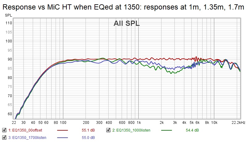
Still need to look at response over heights and pick an equalization height.
What works surprisingly well is 2 groups biamped - 10 drivers spanning the listening window in one group full BW and the remaining drivers in a 2nd group with a FIR low pass filter. I can use IIR filters if that makes a difference but then I need a compensating delay in the full BW channel so it remains two amps per side.
Still need to look at response over heights and pick an equalization height.
This simple 2 way shading scheme that separates the array into HF and MF,LF arrays (at 1500 Hz) doesn't provide a tall listening window. It is quite flat for small changes around the equalization height, however, except for an anomalous dip at 3 khz.
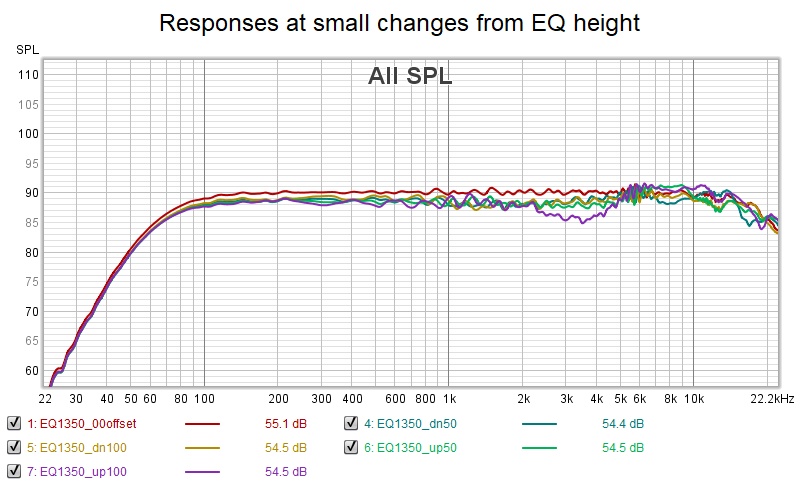
Tried some amplitude shading in the center group for a 1 db improvement in the deviation circa 3 khz. Even if I got the variation within +/= 3db over the entire window I still wouldn't like the frequency of the ripple in the top octave.
Tried some amplitude shading in the center group for a 1 db improvement in the deviation circa 3 khz. Even if I got the variation within +/= 3db over the entire window I still wouldn't like the frequency of the ripple in the top octave.
Attachments
There would be many ways to do the shading, but seemingly we'd need a longer array to get good performance at 3 KHz, so the crossover should move up.
Isn't shading with a bypassed resistor (to keep bottom end) a better solution?
At 2.7 meter, the result up to 5 KHz has always been remarkably clean.
But never mind my situation, what would you choose for your personal array?
These exercises do show it isn't that easy to get something to work over a large area, while most of us who run these arrays (full range) would tell you the difference between sitting and standing isn't as big as some of these graphs make it out to be.
I can hear it being different, no doubt, but it is very gradual and quite acceptable, as is the tonality in the rest of the room.
So far I haven't seen a solution yet that would sway me. But there probably are countless more ways to go about it. I still think we shouldn't have to cut off the top end (with a crossover) but make sure it's well shaded like a high shelf would do. Finding a right mix does seem challenging.
Instead of hacking away, I would like to find something that has some theoretical basis for being good or at least some empirical evidence that it is good. My shade so as to prevent destructive combining had that attribute but also yielded a narrow listening window and is damaged by floor and ceiling reflections. Dave Smith's shading had his endorsement and seem to work fairly well.
What would I choose? an active shading solution so I wouldn't have to choose 🙂 except its difficult/expensive to pull together enough amp and dsp channels in a compact package. But it wouldn't be terribly difficult to do amplitude shading that could be turned off and on.
But my personal array will remain the one I built last year. Its a WAF thing and a covid thing and its something not broken and so doesn't need to be fixed. But I may shade it and at some point I need to reinforce and damp the widest side better.
Simulation hasn't told me otherwise, if anything its reinforced that decision, if decision is indeed what it is.
The key insight from simulation is that in reducing destructive combining, and thus frequency response ripple and combing, shading also narrows the vertical window. Unshaded, we see loss of vertical directivity starting in the upper midrange. Shading delays this or prevents it completely. In doing so, the vertical window is unavoidably narrowed. That tells me NOT to do any more sims in search of a configuration with a wider vertical window.
I've investigated different size drivers and even a 2 way array with planar tweeter. Going back a year or two, I thought I needed greater horizontal dispersion and didn't know what to think about driver spacing. Today I see that driver spacing issues to the extent that they are audible are curable with shading but at the expense of narrowed vertical listening window. My listening experience says I don't need more horizontal dispersion - even though measurements say otherwise; I guess the mic has better hearing than I do. I don't understand though why you don't have your arrays aimed more at the LP than I see in your photos.
So what will I do? For now I'm going to listen to what I have and address other questions that can be answered with simulations.
Instead of hacking away, I would like to find something that has some theoretical basis for being good or at least some empirical evidence that it is good. My shade so as to prevent destructive combining had that attribute but also yielded a narrow listening window and is damaged by floor and ceiling reflections. Dave Smith's shading had his endorsement and seem to work fairly well.
What do you think I made this picture for? At that time I wanted to be prepared for possible shading schemes:

Even before making the fist slice of my translam construction. Though all evidence pointed to not shade floor to ceiling arrays (like that remark from Dave Smith). Even though a lot of arrays I found during research used tweeters, lots of them did not have closer spacing than I could get, see the older Genesis arrays. Those planars are midrange, the tweeters are pretty far apart. Same for lots of McIntosh arrays, where Dave had done analysing and that actually lead to his: "no shading for floor to ceiling" advice. See the paper linked in the first post of my thread.
What would I choose? an active shading solution so I wouldn't have to choose 🙂 except its difficult/expensive to pull together enough amp and dsp channels in a compact package. But it wouldn't be terribly difficult to do amplitude shading that could be turned off and on.
Certainly an option! That would unlock a lot more than shading options alone...
But my personal array will remain the one I built last year. Its a WAF thing and a covid thing and its something not broken and so doesn't need to be fixed. But I may shade it and at some point I need to reinforce and damp the widest side better.
I think you haven't even begun to extract it's true potential. Seriously, there's lots to be had with the DSP tools, I have heard so many different renditions, the hardest part was trying to extract all the good things and put it all into one package.
Simulation hasn't told me otherwise, if anything its reinforced that decision, if decision is indeed what it is.
The key insight from simulation is that in reducing destructive combining, and thus frequency response ripple and combing, shading also narrows the vertical window. Unshaded, we see loss of vertical directivity starting in the upper midrange. Shading delays this or prevents it completely. In doing so, the vertical window is unavoidably narrowed. That tells me NOT to do any more sims in search of a configuration with a wider vertical window.
I've investigated different size drivers and even a 2 way array with planar tweeter. Going back a year or two, I thought I needed greater horizontal dispersion and didn't know what to think about driver spacing. Today I see that driver spacing issues to the extent that they are audible are curable with shading but at the expense of narrowed vertical listening window. My listening experience says I don't need more horizontal dispersion - even though measurements say otherwise; I guess the mic has better hearing than I do.
Wider horizontals just means more room sound. Which does not have to be a bad thing. It all depends on preferences and taste. However I chose to absorb a lot of the wider projected sounds, which I fill in with the ambient setup and can adjust to taste.
I don't understand though why you don't have your arrays aimed more at the LP than I see in your photos.
Extensive testing, really. Ideally, I would have wanted to cross in front of the listening position due to theoretical advantages of that choice. But that just looked plain silly. I started testing the toe-in angles and have done so to find the one that worked best within the room. This was it. I've done the same for distance to back wall. I've opted for free standing arrays as a deliberate choice, so I could test all these things and see/hear what happens. That's why I made the rotational feet.
Room sound certainly has something to do with my final choice. This setup had more potential than simply pointing them at ear positions.
So what will I do? For now I'm going to listen to what I have and address other questions that can be answered with simulations.
Some things are hard to gather from simulations. I've said it before and I'll say it again: take good care of diffraction close to the speakers in the vertical/parallel planes. Not as easy on your corner array unless you use absorption. This will have a small measured effect but one that can be perceived. I would not build square cornered boxes voluntarily. At least not for main speakers. Those shapes make it way easier to pick up speaker position by ear. Even if the measurements don't look all that bad.
Well my current construction has me locked into a corner, literally. That is what I built it for. Eventually I will add ambient channels like you.
I do agree I have more work to do on the DSP end, which I've been avoiding. No doubt I will run out of other things to do soon. I'm kind of burned out on simulations.
I do agree I have more work to do on the DSP end, which I've been avoiding. No doubt I will run out of other things to do soon. I'm kind of burned out on simulations.
a picture to reinforce what I said in the previous post
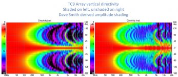
Looking at both these pictures, I still expect improvement in the array behaviour if one were to shade the 5 drivers above and below the center ones above 5K (as from 1K to 6 K we have a pretty good graph unshaded, but the left graph shows less side band influence above 5K. I see no reason to shade them any sooner. The amount of shading could possibly keep pattern control a little higher up the chart. A little goes a long way, basically it would be experimenting.
Also, the narrowing between 5K and 1K isn't there in the shaded example. So the outer drivers could be shaded above about 400-500 Hz. Making the bottom end mimic the D.S. shaded array.
Looking at this presentation:
And assuming both of these graphs were made with the measurement point at the center, the difference in distance between the outer most driver(s) compared to the center driver would be 160mm. Wavelength of 160mm x 4 = 468Hz. 'Probably' responsible for the narrowing around 500 - 1 KHz.
I'm guessing that 'could' make the graph prettier overall. It could also mean you'd actually need to build an array of twice the listening height in length as an ideal devise, so it's always symmetrical around the preferred listening height/position. Making sure to absorb high frequencies enough in floor and ceiling reflections (may not even be hard to do). As these examples do somewhat sim finite arrays. I'm not thinking my arrays act like infinite at high(er) frequencies. Most of what I was hoping for is that it would help out the bottom end.
The low frequency handling would go down, but it could have excellent properties around the listening height. More shelf shading of drivers could bring that back by letting those drivers making up the rest of the length help out the bottom end (below say ~200 Hz).
Do you get what I said about a corner array by the way? That it has 2 extra ridges to worry about? No offence meant, but that's what I see when I look at these corner constructions. Sharp corners/ridges/parallel planes... that's the kind of thing I tried very hard to avoid. A gradual change from baffle to wall could avoid that, but it would make up a strange waveguide in the process. Or... absorbing the energy at the abrupt end of it.
Thinking about the unshaded graph, my ambience channels probably help fill in the 500 - 1 KHz area above seated height (as they are within the Haas limit). Possibly making the narrowing a bit less obvious.
Disclaimer: The array + ambience (when ambience isn't low-passed) sums pretty flat. The ambience channels fall off naturally below 200 Hz.
I still have to try a high shelf instead of a low-pass.
Attachments
Last edited:
To really make an array that has no combing, we would need drivers that beam in the vertical plane. Even the smallest driver spaced within quarter wave distance is going to comb once we add more to the line. A deep but wide horn on each driver? That brings it's own challenges.
For an expanding array a Synergy style source as part of a bass array still makes a lot of sense to me. However that will still create differences in SPL fall off as distances vary.
The fractal array shown on the forum by member bbutterfield could also be a nice variation on a theme.
However, even without solving all compromises I still think there's enough potential in these arrays to get outstanding performance for such a small footprint. If there would be a way to advance its performance while keeping the wider vertical patterns it is going to be worth the effort.
As long as we did not solve this last part, I am more than pleased with what I've got in combination with applied DSP and other tricks.
I might have to learn Virtuixcad to do more simulations though 😀.
Can we share projects among users of Virtuixcad? Together we should be able to find ways to keep the good parts while "softening" the compromises.
I don't think we can widen the pattern and retain the shading benefits but it just occurred to me that it might be possible to create a pattern with twin peaks (actually flat spots) one at seated ear height and one at standing ear height. Yes, I know this is a wild and crazy idea but its a fun thought and I'm going to whip up a model.
The expanding array with, if not a synergy at center, then at least a small waveguide; with just a tweeter you've given up entirely on controlling the directivity within its bandwidth. It will be hard to match vertical directivity between a line and a waveguide; the line can't help but be narrower since its so tall. Perhaps the way to do expanding array is Horbach-Keele; Not with a bass line but with several pairs of increasing larger drivers.
Vituix isn't hard to learn; I can give you models to start with.
but of course we can't have twin peaks, we'd get combing between the two separated groups of full bw drivers
I might install Virtuix just to see my previous suggestion. Keep the center 5 drivers at full force, the two adjacent groups would get shaded with a bypassed resistor at ~5 KHz (but only a fraction at a time to see what happens), the two outer groups at 450 Hz, again with a bypassed resistor (also tested with different values of SPL reduction).
Driven at the center of the array, just to see the basics. If this works, move on to a more specific listening height.
Driven at the center of the array, just to see the basics. If this works, move on to a more specific listening height.
I think you should; you'll see things and optimizations you otherwise wouldn't.
What you describe sounds like a passive version of my active frequency scaled array. I quickly threw together this IIR version, which I had been meaning to do. Little attempt to optimize it; just enough to get a decent response. Mic still at array center, moving off center is another complication. I'm not sure where the net Z ended up; for some reason its off the scale in the Vituix graph.
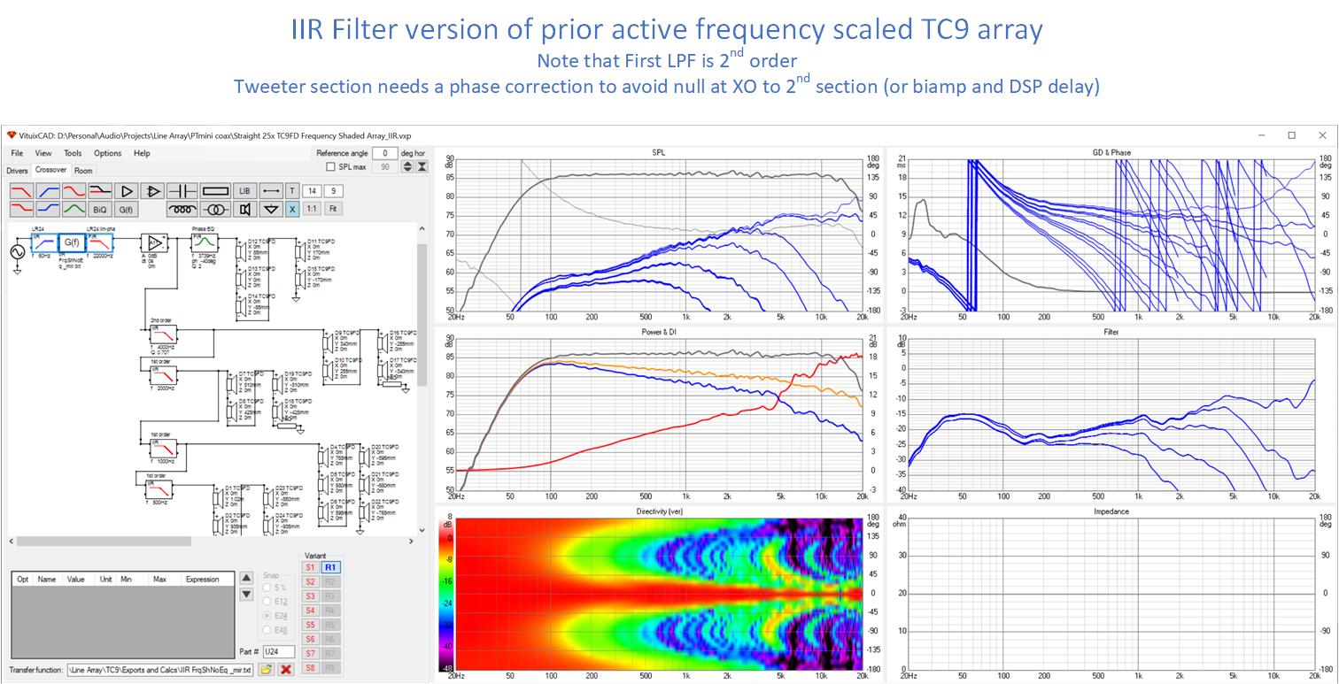
I had to make the first low pass 2nd order to get a decent response and I had an XO null near its corner that I fixed with a phase correction element, which suggests biamping. The rest of the filters are first order
The results aren't as nice as the active version and the narrowing of the vertical is still there; perhaps a little wider, perhaps due to the higher level of vertical sidebands. There are lots of things to explore in your own simulation that might or might not improve it.
What you describe sounds like a passive version of my active frequency scaled array. I quickly threw together this IIR version, which I had been meaning to do. Little attempt to optimize it; just enough to get a decent response. Mic still at array center, moving off center is another complication. I'm not sure where the net Z ended up; for some reason its off the scale in the Vituix graph.
I had to make the first low pass 2nd order to get a decent response and I had an XO null near its corner that I fixed with a phase correction element, which suggests biamping. The rest of the filters are first order
The results aren't as nice as the active version and the narrowing of the vertical is still there; perhaps a little wider, perhaps due to the higher level of vertical sidebands. There are lots of things to explore in your own simulation that might or might not improve it.
Attachments

Oh, I see re' Z
The IIR filter blocks confuse Vituix. To see a netZ, I would need to replace them with L's and in one case an LC
The IIR filter blocks confuse Vituix. To see a netZ, I would need to replace them with L's and in one case an LC
Not quite what I had in mind. The reason for me not to dive into Vituix is that I need to learn how to apply what I want it to show.
My suggested setup only had 3 groups. One center 5 drivers, running full range. 2 groups of 5 drivers each running up to 5K and shelve-shaded above that, so a resistor bypassed with inductor to lower high frequency content above 5 KHz while keeping the same SPL levels below 5K.
2 more groups of 5 drivers (top and bottom) that have a similar high shelf-shade applied for anything above 450 Hz.
Again, resistor bypassed with inductor. Creating that shelved result. The variables are the SPL level that is used to shade, seeing how that influences the graphs.
We know what the non shaded array looks like, this is to improve the 500-1 Khz and the top end above 5K.
You are shading way more drivers than I would and it is obvious that eats away from the good things the unshaded array shows us. At least in my mind. 😉
Those would be my ingredients, but I'd need to learn how to apply the directivity to the drivers, learn how and where to EQ etc.
I have limited time, this learning curve is going to take time... so it isn't for me right now. At some point it may be... maybe when I'm without a setup when my home renovation starts... (while I do have some spare time on my hands, I'm filling a website I started. Not as meaningful or helpful, but I can walk away from it whenever I need to. Learning a new tool with lots of options requires much more attention 🙂)
Last edited:
To really make an array that has no combing, we would need drivers that beam in the vertical plane. Even the smallest driver spaced within quarter wave distance is going to comb once we add more to the line. A deep but wide horn on each driver? That brings it's own challenges.
A box with 60 3” SB10PGC21-4 / Fiberglass – Sbacoustics is on its way to me, and my first project with them will be an open baffle line array.
I read through a lot of the info available here and the beaming at HF pops up every time again. So just some days ago I had the idea of avoiding the beaming by some physical means, indeed, a waveguide that will force HF to beam in the vertical plane. I was about to ask about this in this thread, when I saw your post.
Unfortunately I have no idea how to design a waveguide, so will start mine with bare drivers, but if some ideas come up I could use our 3D printer to do some prototypes and measure them at home.
Best regards,
erik
A high aspect ratio planar or ribbon driver is one that would beam vertically. The beaming you hear about is probably horizontal beaming from a line of 3-4" drivers, which do beam compared to the usual 3/4" tweeter. But this doesn't seem to be much of an issue in the real world, as opposed to the simulation world, and you can always aim your arrays close to your listening position.
What provides vertical directivity in a line array is the way that stack of 30 or so drivers in a line sum together. A waveguide wouldn't help in the vertical unless we are discussing a single driver or a very small number of drivers.
What provides vertical directivity in a line array is the way that stack of 30 or so drivers in a line sum together. A waveguide wouldn't help in the vertical unless we are discussing a single driver or a very small number of drivers.
Sorry, not what I'm talking about.
The vertical beaming driver I propose is to eliminate combing all together.
Spacing two drivers, a quarter wave separated sum as if they are one. Add another above it and the quarter wave spacing is not valid anymore for all possible listening positions.
It was just a theoretical blurb... nothing more, nothing less. Nothing to do with our arrays, just theory in mind.
Sorry, not what I'm talking about.
The vertical beaming driver I propose is to eliminate combing all together.
Spacing two drivers, a quarter wave separated sum as if they are one. Add another above it and the quarter wave spacing is not valid anymore for all possible listening positions.
It was just a theoretical blurb... nothing more, nothing less. Nothing to do with our arrays, just theory in mind.
Hi guys, been following along with great interest...
Basic line array question...
My understandings are:
that a line behaves as a line, ie no combing, when 1/4WL spacing exists top to bottom.
that the tightness of the 1/4WL spacing will determine the highest frequency the line will continue to behave as a line
and that the length of the line determines the lowest frequency the line will exert vertical control over. (common rule of thumb seems to be WL of lowest freq = about 1/4 line length.
Do these understandings square with yours?
And re beaming...
Usually, when I hear 'beaming' used, it's in the context of trying to use too larger a circular driver to reach too high a frequency, and both horizontal and vertical patterns collapse or narrow too much.
With a line array, I'm not sure using 'beaming' makes sense.....because horizontal never collapses,
and really don't I want the line to "beam" vertically, ....as in putting out a continuous beam running from top to bottom, that's perpendicular to the line top to bottom?
I know on my electrostats which are about 5 ft tall, once ear level is perpendicularly above the top of the panel, HF/VHF drops off a cliff...astounding really.
But any where perpendicularly between the top and bottom, HF/VHF is very constant. Sit at any height, sounds near the same. Floor bounce, etc, is all that changes.
I bring them up because I view the electrostats as a line array (vertically). And that they have 1/4WL spacing all the way to 20kHz...
maybe that's a mistake to consider them lines???
Let me show my previous post by adding a couple of pictures...
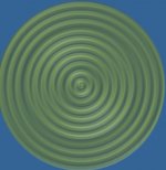
2 sources spaced a quarter wave apart:
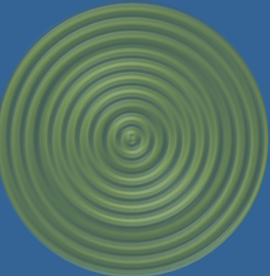
Click on picture to enhance...
No matter what angle you view it from, it has no comb lines.
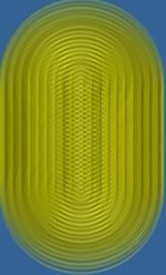
Now add a couple of sources, making it 5 in a row, still spaced a quarter wave apart:
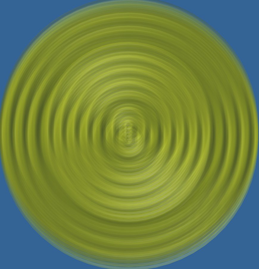
Click on picture to enhance...
See how we get combing? except on the frontal lobe?
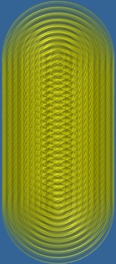
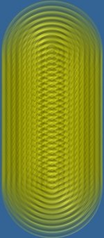
Now lets examine 25 in a row:
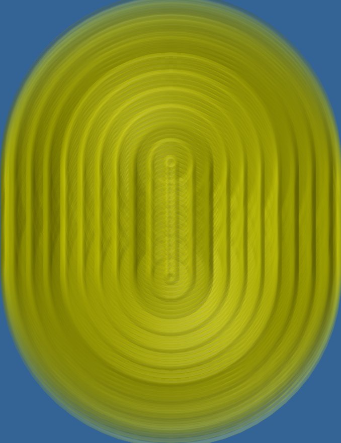
Here's what the line theory is all about, it looks like a flat wave front is emerging from the source...
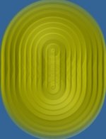
Now lets look at the same situation but where the drivers are half a wavelength apart:
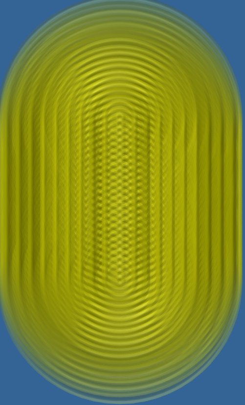
In this case, the further you move away from the source, the more it looks like a flat wavefront.
One wavelength apart:
I did not add enough sine-shaped waves to clearly show the protruding flat waveshape here...
It will be there though, at enough distance but it is clear to see the advantage of closer spaced drivers.
Make your own conclusions 😉.
So I do think it could have merit to use a waveguide to shape the driver response.
I do remember a member here made such a setup with a couple of tweeters...
Member Patrick Bateman has shown that picture more than once on his threads...
Found him: http://hannover-hardcore.de/infinity_classics/!!!/Dokumentation%20Linienstrahler%20Prototyp.pdf

2 sources spaced a quarter wave apart:
Click on picture to enhance...
No matter what angle you view it from, it has no comb lines.
Now add a couple of sources, making it 5 in a row, still spaced a quarter wave apart:
Click on picture to enhance...
See how we get combing? except on the frontal lobe?
Now lets examine 25 in a row:
Here's what the line theory is all about, it looks like a flat wave front is emerging from the source...
Now lets look at the same situation but where the drivers are half a wavelength apart:
In this case, the further you move away from the source, the more it looks like a flat wavefront.
One wavelength apart:
I did not add enough sine-shaped waves to clearly show the protruding flat waveshape here...
It will be there though, at enough distance but it is clear to see the advantage of closer spaced drivers.
Make your own conclusions 😉.
So I do think it could have merit to use a waveguide to shape the driver response.
I do remember a member here made such a setup with a couple of tweeters...
Member Patrick Bateman has shown that picture more than once on his threads...
Found him: http://hannover-hardcore.de/infinity_classics/!!!/Dokumentation%20Linienstrahler%20Prototyp.pdf
Attachments

Last edited:
- Home
- Loudspeakers
- Full Range
- Full range line array for wall or corner placement