Yesterday, I made the aphoristic comment that destructive combining was the root of all evil for full range line arrays. Later, out of the blue I realized I could frequency shade to cut off each driver before the phase shift due to its delta path delay relative to center driver reached 90 degrees. Then there would be no destructive combining!
This led to this spreadsheet (inadvertently attached to previous post) which suggested the banking and cutoff frequencies indicated in it:
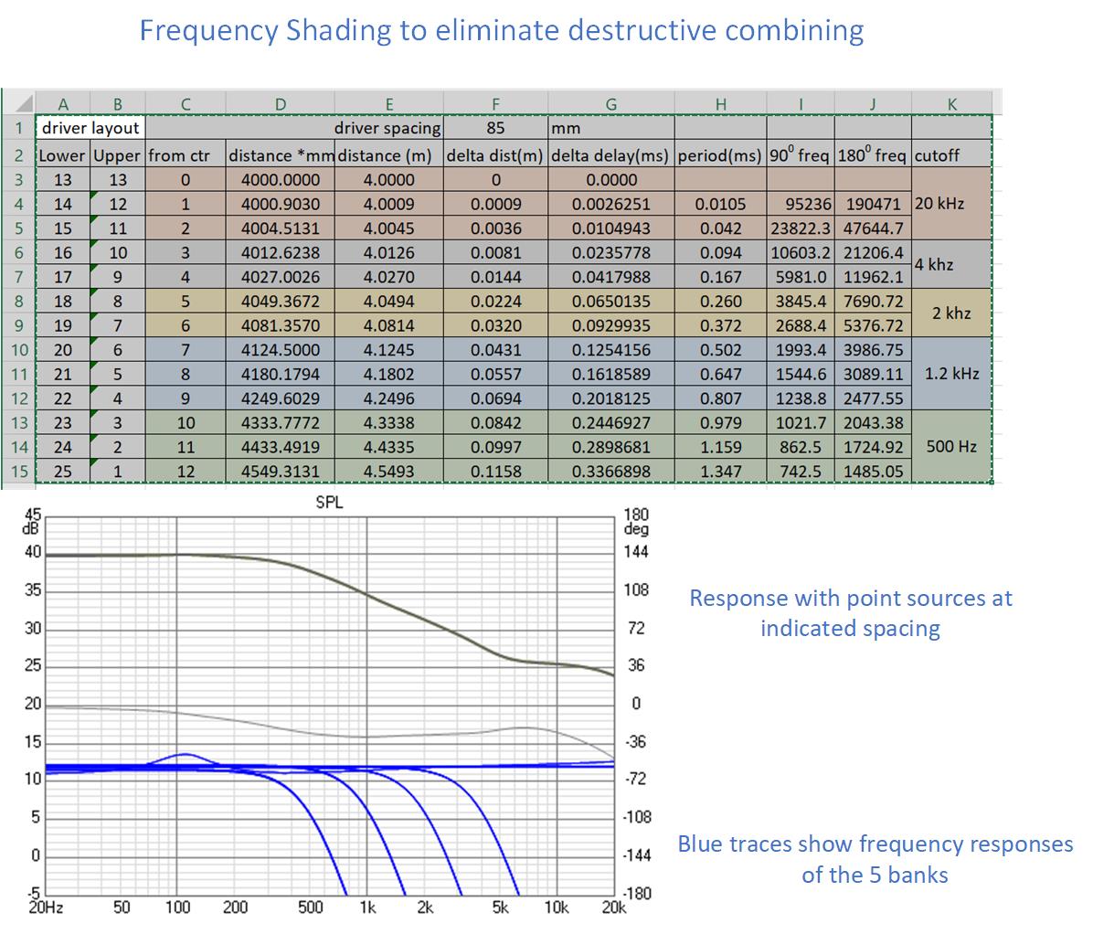
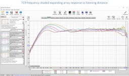
What happens here is that fewer drivers contribute at the higher frequences but no drivers contribute destructively. You don't get roll off in the high end so much as rising response towards the low end as the lower you go, the more drivers contributing all constructively. In that sense it is an expanding array!
Going on to a full simulation:
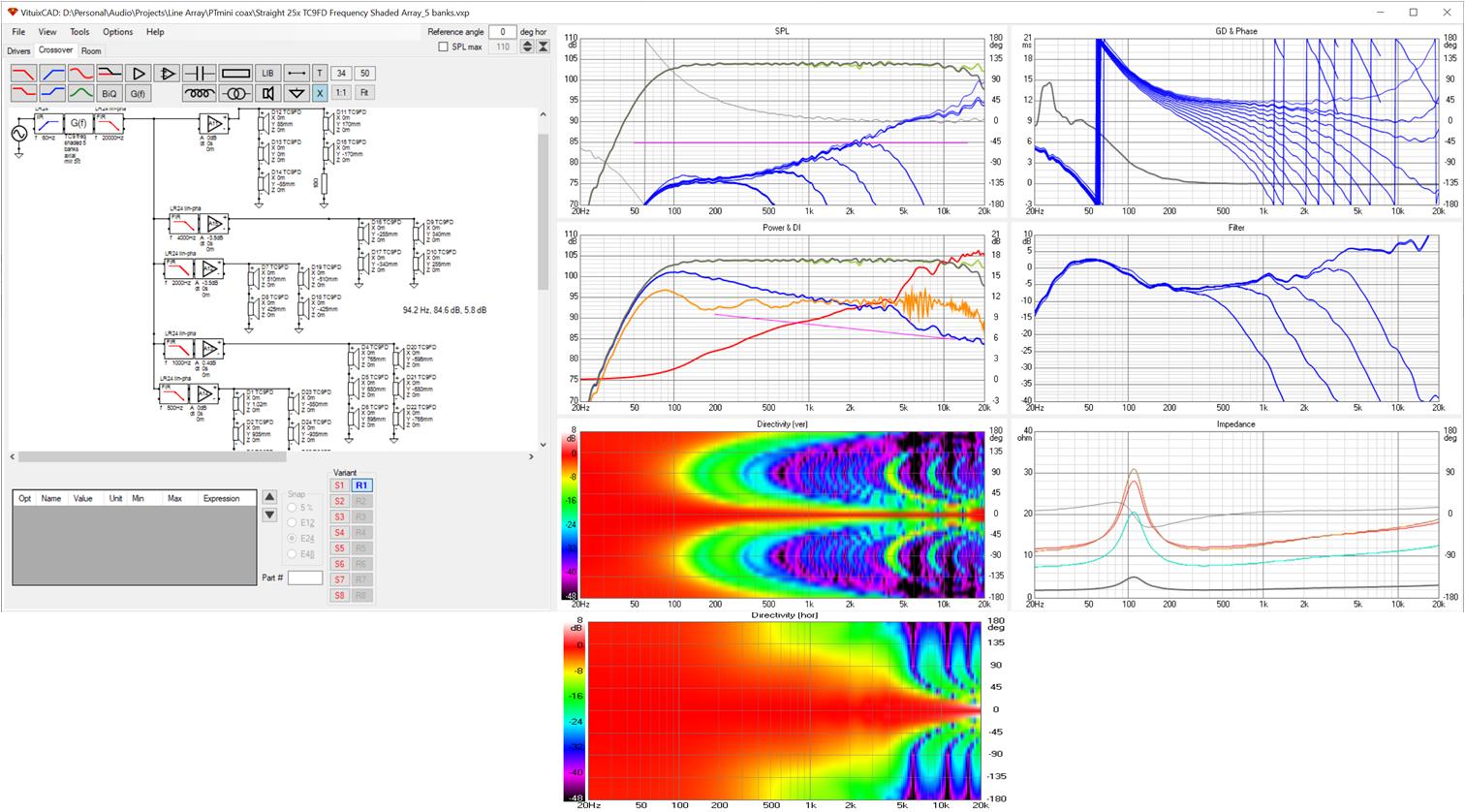
I plugged in the weights and corner frequencies from the spreadsheet, tried LR4 linear phase slopes, IR inverted the axial response and went for it. Chances are IIR or even passive filters can be made to work. I also had a 4 bank version that seemed to work just about as well.
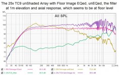
There isn't a hint of combing in this response. Vertical sidelobes in the top two octaves are significantly reduced as are ceiling and floor splash visible in the orange room response trace.
I see a lot of promise in this approach. The drivers don't all have to be the same size. One could use smaller ones at the center for wider horizontal dispersion and larger ones at the edges to extend the low end. The only downside I see is the number of amplifiers and, so far at least, DSP channels needed. That can be worked on.
This led to this spreadsheet (inadvertently attached to previous post) which suggested the banking and cutoff frequencies indicated in it:
What happens here is that fewer drivers contribute at the higher frequences but no drivers contribute destructively. You don't get roll off in the high end so much as rising response towards the low end as the lower you go, the more drivers contributing all constructively. In that sense it is an expanding array!
Going on to a full simulation:
I plugged in the weights and corner frequencies from the spreadsheet, tried LR4 linear phase slopes, IR inverted the axial response and went for it. Chances are IIR or even passive filters can be made to work. I also had a 4 bank version that seemed to work just about as well.
There isn't a hint of combing in this response. Vertical sidelobes in the top two octaves are significantly reduced as are ceiling and floor splash visible in the orange room response trace.
I see a lot of promise in this approach. The drivers don't all have to be the same size. One could use smaller ones at the center for wider horizontal dispersion and larger ones at the edges to extend the low end. The only downside I see is the number of amplifiers and, so far at least, DSP channels needed. That can be worked on.
Attachments

re' there isn't a hint of combing
the ripple that can be seen in the axial response is because my equalization reference was the 6th octave smoothed data sheet response.
the ripple that can be seen in the axial response is because my equalization reference was the 6th octave smoothed data sheet response.
I've been looking at these graphs for a while now and I'd like a little explanation about something that has been bugging me.
The vertical off-axis plot. How do I look at that? Or phrased otherwise, when does the off axis angle begin?
Horizontal is easy, but vertically, when am I going off axis, if I move the LP above (or below) the array? As it can't be that of-axis starts to count from the center position of the array. Our array is pretty large. Yet there is no audible difference until we either get a) close to the floor position or b) move above the array height. It does not present well in a graph like this. As if I move from sitting to standing I'm changing the vertical off axis angle if I were listening to a single driver, but here we have multiples. I stay on axis of at least part of the array as seen from either position, sitting or standing.
The small plot of angles shown here does not define what I hear out in the (real) room. Unless the off axis begins above or below the array.
Also, the 'ceiling splash'... I do have difficulty with that assumption too. The actual reflections from a perfect reflecting floor or ceiling should make the array seem longer (approaching infinite) in an ideal world. So the splash is there if the array falls short of being floor to ceiling. Or if the floor and ceiling reflections are less than ideal (as it is in our real world). We should first mimic the infinite array in our simulations. What assumptions are made of floor and ceiling properties in these plots?
However an expanding array sure is interesting, it has been on my mind before even starting the build I did. These frequency dependent shading options are the only thing I would ever consider though. Done passively.
I don't quite see why you'd do it LR4 linear phase? As you want the phase to turn to shade the frequency for each section. As a big multi version of a 1.5 way.
Just random thoughts after a day at work, don't read too much into it. Just unloading my brain here, might just be brain farts 😀.
Last edited:
The question of vertical angle is a good one. It stumped me for a while and wasn't answered until Kimmosto added the microphone offset option box is the room response tab. Now, if you turn off reflections in the room response tab, you can see how response varies with microphone offset from the center of the array. I think I've posted some REW graphs that show data collected that way. You say response doesn't vary audibly as you move the mic up and down but as ra7's posted measurements and my simulations show, it does vary measurably. The arrays have very narrow vertical beams and you don't need to move up or down very much to see a change but the changes aren't that great. IIRC, they stay within 4-6 db if you don't get the mic elevation too close to top or bottom of the array height. I believe the axis is indeed at the vertical center of the array.
Ceiling splash is the term I invented for the noisy wiggles in the upper midrange and treble I get on the room response curve when I enable floor and ceiling reflections in the room response window. These are highly correlated with vertical sidelobes which appear prominently in unshaded arrays when the driver spacing gets large enough compared to the wavelength and which are significantly reduced by shading. When I reduce or eliminate the sidelobes with shading, what I called ceiling splash reduces or goes away. This is pretty clear cause and effect, not an assumption. The vertical sidelobes scatter energy off floor and ceiling which comes back to the microphone in the room response curve. This is entirely consistent with theory or previous research results- that when spacing gets large compared to wavelength, vertical directivity control is lost.
Except that theory itself breaks down when driver spacing gets large compared to the wavelength and the only ways you can learn what happens is to measure or run simulations. That is why I've been doing this.
Infinite arrays can't be simulated in Vituix, only approximated. The best I can do is room response with floor and ceiling reflections enabled and I believe its just the first order reflection that are summed to the microphone position. I tried simulations that included ground and ceiling image drivers but quickly ran into Vituix baffle height and number of driver limitations. In addition, the destructive combinations from those even more distant image drivers really chopped up the treble. That is why I've in the past suggested we would benefit from a modicum of absorption on the floors and ceiling.
Succeeding with an expanding array is interesting, even exciting. To see a smooth treble response trace emerge from the simulation where previously I had seen severe combing was gratifying.
My choice of slopes was a guess and worked so well I didn't try anything else. I wanted to see quickly how well it could work. The benefit of linear phase filter is the filter delay doesn't add to the delta distance delay complicating things. I've no doubt a passive solution can be implemented the filter slopes don't look at all critical; you've just got to get each driver's response attenuated before its delta distance phase shift plus uncompensated filter phase shift rotates past 90 degrees to be subtractive. Hopefully, a string of inductors in series with a tap for each bank except the center can be made to work, amplifier load impedance issues aside for the moment.
Thanks for the interest and good questions.
Last edited:
one thing I should point out that might not be obvious until you dig into my spreadsheet -
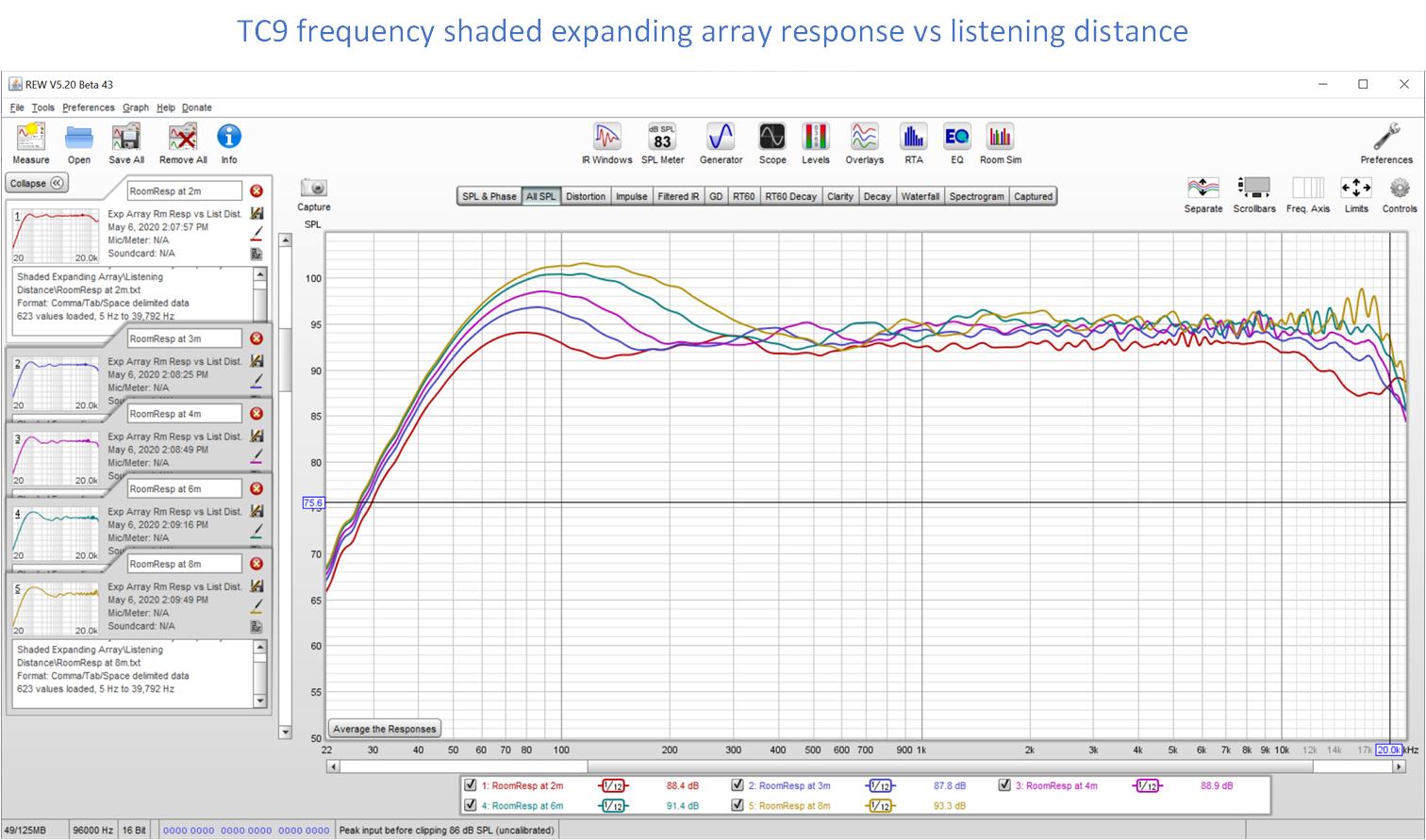
the fllter corner frequencies that it calculates depend on the listening distance. The calculation should be done for the closest listening distance anticipated. Then if you move back the filters will still work although their corner frequencies will be lower than they need to be for the increased listening distance.
Which reminds me: I did the spreadsheet for a 4m listening distance but I had Vituix set for 3m out of habit. Correcting that I see very little change - less than a db -in the axial response over range of 3m to 6m. You can even listen at 2m with this shading although you will lose some of the high treble.
The room response curves do vary more over this range. Most of that variation is in the bass region.
Attachments
Explain the vertical angles again, but after looking at my measuring distance.
Not quite at 3 meter, I measure at 2.7 meter. But I can never be more off-axis than 20 degree below my measurement/correction position, I'm 14 degree off axis when standing up and cannot be more than 34 degree off axis above the measuring/correcting position. So a simulation of a floor and ceiling should take these realities into account I'd say. That's where the ceiling splashes 😉. We can't be under the floor or above the ceiling. Yet I cannot see that in these graphs, as they do not show any boundaries.
The presentations from Keele for his CBT, use the floor as reflective for a CBT, but not for the 1 meter long array. So no help there.
How much deviation would you expect between listening seated and standing up?

I don't have real floor to ceiling coverage of drivers. Not a surprice for those that have seen my pictures. This drawing represents my reality. Yet I don't think these simulations tell me what I experience.
Sure, there is audible deviation, but the listening window predicted just doesn't seem right to me. Can you explain that away?
Part of where the mystery begins, my measurement position is at about 1 meter height. That isn't the center of my array.
The center lies at ~1.197 meter height. So I expect a reasonable symetry from the array around that measurement spot.
As at 1.394 m height I have a similar amount of drivers below/above as at my measurement position. The floor complicates
things but these things never show up in a simulation, even when including floor or ceiling reflections.
Who measures/corrects these type of arrays at the center of the array? All raise your hand if you do...
Not quite at 3 meter, I measure at 2.7 meter. But I can never be more off-axis than 20 degree below my measurement/correction position, I'm 14 degree off axis when standing up and cannot be more than 34 degree off axis above the measuring/correcting position. So a simulation of a floor and ceiling should take these realities into account I'd say. That's where the ceiling splashes 😉. We can't be under the floor or above the ceiling. Yet I cannot see that in these graphs, as they do not show any boundaries.
The presentations from Keele for his CBT, use the floor as reflective for a CBT, but not for the 1 meter long array. So no help there.
How much deviation would you expect between listening seated and standing up?
I don't have real floor to ceiling coverage of drivers. Not a surprice for those that have seen my pictures. This drawing represents my reality. Yet I don't think these simulations tell me what I experience.
Sure, there is audible deviation, but the listening window predicted just doesn't seem right to me. Can you explain that away?
Part of where the mystery begins, my measurement position is at about 1 meter height. That isn't the center of my array.
The center lies at ~1.197 meter height. So I expect a reasonable symetry from the array around that measurement spot.
As at 1.394 m height I have a similar amount of drivers below/above as at my measurement position. The floor complicates
things but these things never show up in a simulation, even when including floor or ceiling reflections.
Who measures/corrects these type of arrays at the center of the array? All raise your hand if you do...
Attachments

Last edited:
The simulations don't model your situation exactly. Is that a surprise? Of course not. We do the best we can in simulations within model limits and keep those limits in mind when using them to predict what will happen in the physical world.
The room response simulation can tell us the difference in response for moving the microphone up or down some amount from the height for which equalization was performed, provided reflections are turned off for the simulation. Those are the limitations. The equalization reference height is about 8" off center for you. I'm not sure how big a difference that makes. I would have to export a room response from Vituix at your mic height, use it as an auto eq target in REW/rephase and bring the filter back into Vituix in order to find out. I'm not sure how hard that would be; maybe an hour's work (famous last words).
For myself, I don't need to do that. I've just been comparing sims of shaded vs unshaded arrays to see if there is a case for shading. I think my frequency shaded expanded array concept speaks for itself and justifies the meandering effort that preceded it.
Here's the raw measurements from ra7 at 12 ft distance and the following
heights:
36" or 0.9144 meter
48" or 1.219 meter
60" or 1.524 meter
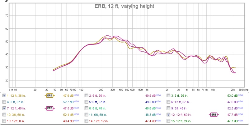
Looks quite acceptable to me, as it did back then. That kind of variation I can relate to.
While these simulations can serve a purpose, as with the shading research, don't put all your trust into it without checking the real world results. Don't roll with the simulations in blind faith.
One of the biggest reasons for me not to try frequency dependent shading is I want to keep what I have, which is that even response I get, both when sitting (where it's measured and corrected) and standing up.
It really does not change all that much. Making me question the assumed listening window in these vertical plots.
That doesn't mean we can not improve on what we get though. For that simulations help a great deal.... if the real world results agree with them 😉.
heights:
36" or 0.9144 meter
48" or 1.219 meter
60" or 1.524 meter
Looks quite acceptable to me, as it did back then. That kind of variation I can relate to.
While these simulations can serve a purpose, as with the shading research, don't put all your trust into it without checking the real world results. Don't roll with the simulations in blind faith.
One of the biggest reasons for me not to try frequency dependent shading is I want to keep what I have, which is that even response I get, both when sitting (where it's measured and corrected) and standing up.
It really does not change all that much. Making me question the assumed listening window in these vertical plots.
That doesn't mean we can not improve on what we get though. For that simulations help a great deal.... if the real world results agree with them 😉.
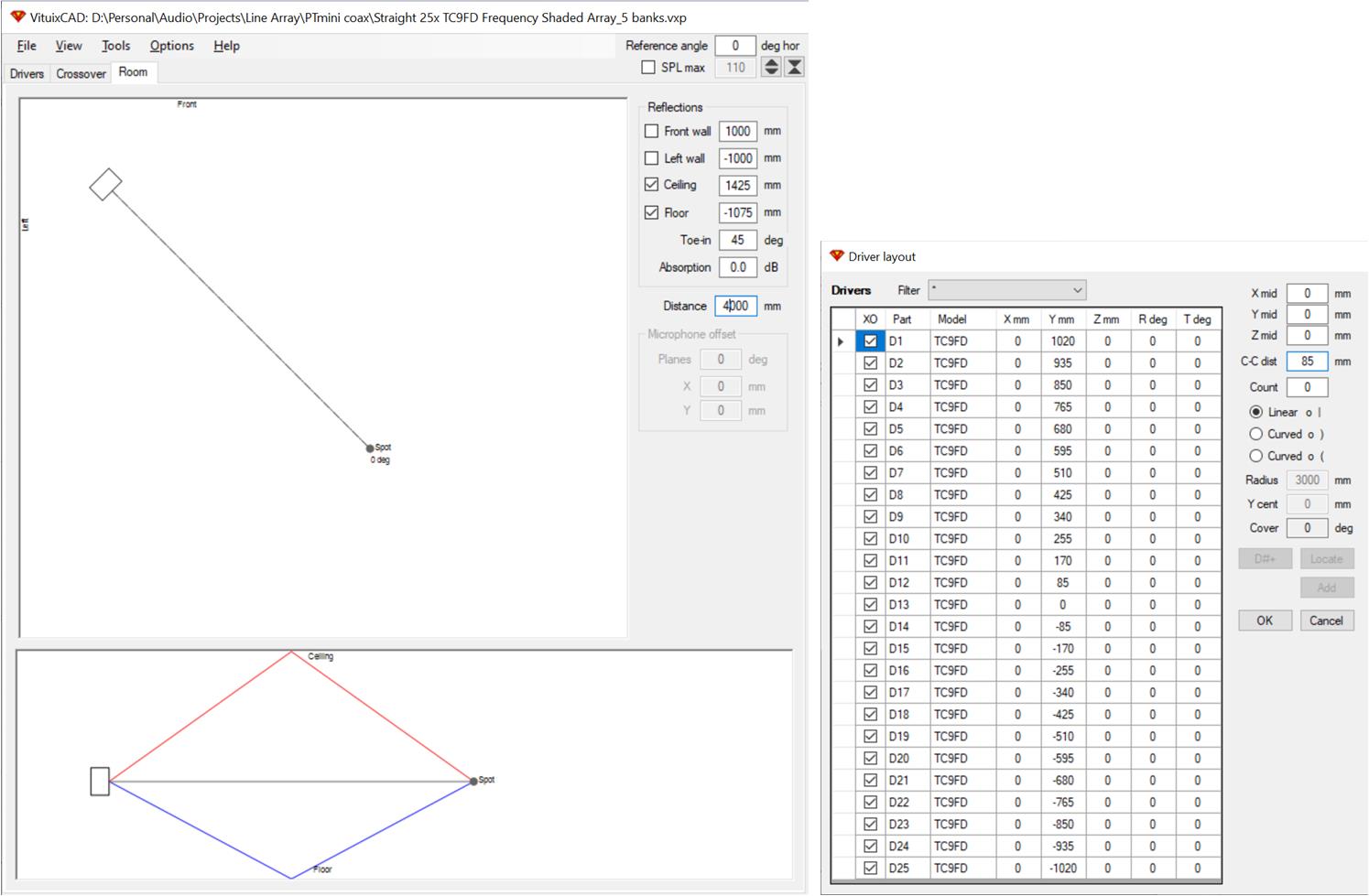
I guess I didn't answer where the floor was in a Vituix simulation. The only place it exists is in the room response tab. On its right edge are check boxes for which reflections you want contributing to the room response. If no reflections are checked, the microphone offset table becomes un-greyed-out and you can move the microphone relative to array center. The driver location table can be edited to move or re-0rient drivers.
The axial response is the anechoic response in free space which has no floor or ceiling.
Re' Don Keele: when I do a groundplane CBT I always input the full curve considering the bottom half of the array to be the ground image.
The axial response is the anechoic response in free space which has no floor or ceiling.
Re' Don Keele: when I do a groundplane CBT I always input the full curve considering the bottom half of the array to be the ground image.
Attachments
The simulations don't model your situation exactly. Is that a surprise? Of course not. We do the best we can in simulations within model limits and keep those limits in mind when using them to predict what will happen in the physical world.
The room response simulation can tell us the difference in response for moving the microphone up or down some amount from the height for which equalization was performed, provided reflections are turned off for the simulation. Those are the limitations. The equalization reference height is about 8" off center for you. I'm not sure how big a difference that makes. I would have to export a room response from Vituix at your mic height, use it as an auto eq target in REW/rephase and bring the filter back into Vituix in order to find out. I'm not sure how hard that would be; maybe an hour's work (famous last words).
For myself, I don't need to do that. I've just been comparing sims of shaded vs unshaded arrays to see if there is a case for shading. I think my frequency shaded expanded array concept speaks for itself and justifies the meandering effort that preceded it.
As I said in the previous post, I see some things I do not believe in in these plots, as I haven't seen it in 1.5 years of measurements (a while ago).
So based on that experience I cannot put that much faith in what we see.
We see the 180 degree mirror image in the plots, but the floor/ceiling addition we see in these predictions still does not make sense. Not if I compare them to real world measurements.
I merely used my situation as an example. I would have noticed changes that big (what simulations predict) between sitting down and standing up. Just saying...
So without a really nice environment with an array to test in and see how much the real world agrees with the simulations, we simply have to put enough trust into it to try one of these schemes in a less ideal room...
But I'd rather see you try to get the most out of your current driver choice first, to be honest. They did not get a fair deal yet, if you ask me.
Re' Don Keele: when I do a groundplane CBT I always input the full curve considering the bottom half of the array to be the ground image.
Yet he never did for the straight array....
Last edited:
I guess I didn't answer where the floor was in a Vituix simulation. The only place it exists is in the room response tab. On its right edge are check boxes for which reflections you want contributing to the room response. If no reflections are checked, the microphone offset table becomes un-greyed-out and you can move the microphone relative to array center. The driver location table can be edited to move or re-0rient drivers.
The axial response is the anechoic response in free space which has no floor or ceiling.
I do get that, as that's what I do see in these plots. But that does not make me feel different about the point I was making. That's just a piece of theory that doesn't work in real life.
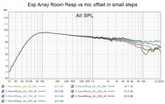
I was going to pull that graph up but you beat me to it. I have yet to show the equivalent for the same array but here is one now; not quite the same but close enough.Here's the raw measurements from ra7 at 12 ft distance and the following
heights:
36" or 0.9144 meter
48" or 1.219 meter
60" or 1.524 meter
Looks quite acceptable to me, as it did back then. That kind of variation I can relate to.
While these simulations can serve a purpose, as with the shading research, don't put all your trust into it without checking the real world results. Don't roll with the simulations in blind faith.
One of the biggest reasons for me not to try frequency dependent shading is I want to keep what I have, which is that even response I get, both when sitting (where it's measured and corrected) and standing up.
It really does not change all that much. Making me question the assumed listening window in these vertical plots.
That doesn't mean we can not improve on what we get though. For that simulations help a great deal.... if the real world results agree with them 😉.
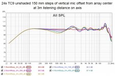
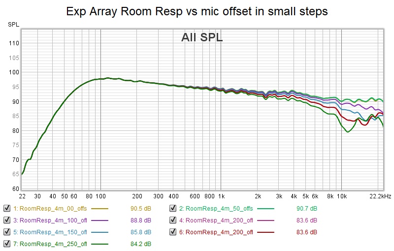
ERB smoothing, equalized at 3m listening distance with mic at array enter. no floor or ceiling support. Steps of 150, 300, 450, 600 mm away from array center. S
It may differ in detail from ra7s but the amount of variation is remarkably close.
Re keeping of evenness of response.
My shading algorithm can only make it better. The unevenness that comes from destructive combination (driver responses arriving at microphone >90 degrees out of phase from center driver's response) is eliminated. Other causes of un-evenness are unaffected.
Give me a few minutes and I'll do the same graph for the frequency shaded array
Attachments
Here is the response vs mic offset for the expanding array. Its remarkably even until we bump into the narrow vertical directivity and start losing treble.
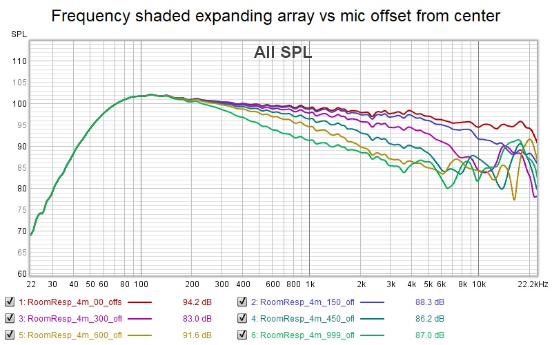
Yes, the vertical window is only +- 5 degrees
Perhaps that drawing board will need to be revisited🙂
might have to allow some destructive combination to get a wider vertical window or we put in a real tweeter in that central position - which would have wider dispersion but which the array would not be able to control
and I bet we get some destructive combination when we move the mic so far up or down that contributions from the then most distant end of the array exceed 90 degrees phase shift
Attachments
Last edited:
Which should mean that the area between plus and minus 600 mm is a good listening height? That's a 1.2 m wide sweet spot vertically within a reasonable variation. What are the angles of that area?
It would be even better/wider if you were to equalize below center. As equal distance above center you would get back the exact same situation. Making for a much wider vertical sweet spot, as seen in practice.
It would be even better/wider if you were to equalize below center. As equal distance above center you would get back the exact same situation. Making for a much wider vertical sweet spot, as seen in practice.
Last edited:
Here is the response vs mic offset for the expanding array. Its remarkably even until we bump into the narrow vertical directivity and start losing treble.
Yes, the vertical window is only +- 5 degrees
Perhaps that drawing board will need to be revisited🙂
might have to allow some destructive combination to get a wider vertical window or we put in a real tweeter in that central position - which would have wider dispersion but which the array would not be able to control
Now you see my point of me, moving away of that frequency shading idea? As said, I'd like to keep the vertical window....
Which should behave even better equalized below the actual array center out in a room.
There are reasons for floor to ceiling arrays, not sure these simulations portray all of them equally good...
I think you are getting my point. But this simulation did help to prove that point, and it can be made into an even bigger difference.
The simulations are pretty cool, but do not show every variable to make it comparable to real life. Unless we know enough to chase that.
It's almost the same as with DSP. DSP does exactly as we tell it to. The problem is knowing what you want out of it...
Last edited:
According to your picture, you need a 700 mm tall listening window. That can be provided IFF the drivers over that range of elevations plus some margin are driven full range. Thats 9 TC9s, maybe 10. In my initial expanding array, only 5 drivers are driven full range and they are centered at array center. Its obvious how to fix that. Once I do I will have to equalize to the reflection free room response curve in order to offset the mic.
Yes I agree I shouldn't be equalizing with mic at array center. I either want the mic at seated ear height or midway between seated and standing ear height. My implicit assumption all along has been that if I could get a good response equalizing at array center, I could get one just as good equaling offset from array center. One reason for this assumption/belief is based on the infinite array model - that the response is the same at any height.
If we are going to compare simulation to measurement than we first need to do all that we can to align the simulation with the array whose measurements we have.
Yes. So we can check what we want out of it. Running simulations all by themselves can be misleading.
Look at how bad of a rep DSP often gets. DSP itself isn't to blame. We need to learn what we want it to do. That alone took me long enough 😀.
Look at how bad of a rep DSP often gets. DSP itself isn't to blame. We need to learn what we want it to do. That alone took me long enough 😀.
Couple of things in the light of a new day:
Physics/geometry sets clear limits on the vertical window of this style expanding array. There is a limited height of a string of drivers over which that 90 degree phase shift window can be maintained. If you move the mic off vertical center, its now closer to some drivers and further from others, so that the 90 degree phase shift rule may be violated and some destructive combining may occur. I tried several things this AM but was never able to get a window tall enough for both seated and standing. What this shading provides is a single listening height solution that is exceptionally constant over perhaps a 12" vertical window but suffers increasing loss of treble as you move up or down outside that window. I think this tradeoff of smoothness and reduction of combing within the window goes hand in hand with a narrower vertical window for the shading algorithms I presented earlier.

I found out that the offsetting the mic in the room response tab does affect the axial response and the polar maps in the main screen. Its not onerous to equalize to an offset mic. Lots to play with there.
How best to model the quasi infinite line array?
If Vituix doesn't fight back, the best way is to include ground and ceiling image drivers and then will see effect of ground and ceiling reflections when offsetting microphone. I will try this...I'm confident I can include a ground image, perhaps not ceiling also.
Over what frequency range does quasi infinite line array model apply:
- certainly where the driver remains omni. The beamwidth for the TC9 is omni below 500 Hz or so and stays wider than +-90 degrees until almost 2 khz
- certainly not above 12 khz where it beams
- at for example 5 khz or so, the beamwidth is about +- 45 degrees. Geometry shows that the 2nd and higher order floor and ceiling reflections return to mic height behind the mic so modelling a single floor and ceiling reflection should be fairly accurate above 5 khz where we have the most concern.
Physics/geometry sets clear limits on the vertical window of this style expanding array. There is a limited height of a string of drivers over which that 90 degree phase shift window can be maintained. If you move the mic off vertical center, its now closer to some drivers and further from others, so that the 90 degree phase shift rule may be violated and some destructive combining may occur. I tried several things this AM but was never able to get a window tall enough for both seated and standing. What this shading provides is a single listening height solution that is exceptionally constant over perhaps a 12" vertical window but suffers increasing loss of treble as you move up or down outside that window. I think this tradeoff of smoothness and reduction of combing within the window goes hand in hand with a narrower vertical window for the shading algorithms I presented earlier.
I found out that the offsetting the mic in the room response tab does affect the axial response and the polar maps in the main screen. Its not onerous to equalize to an offset mic. Lots to play with there.
How best to model the quasi infinite line array?
If Vituix doesn't fight back, the best way is to include ground and ceiling image drivers and then will see effect of ground and ceiling reflections when offsetting microphone. I will try this...I'm confident I can include a ground image, perhaps not ceiling also.
Over what frequency range does quasi infinite line array model apply:
- certainly where the driver remains omni. The beamwidth for the TC9 is omni below 500 Hz or so and stays wider than +-90 degrees until almost 2 khz
- certainly not above 12 khz where it beams
- at for example 5 khz or so, the beamwidth is about +- 45 degrees. Geometry shows that the 2nd and higher order floor and ceiling reflections return to mic height behind the mic so modelling a single floor and ceiling reflection should be fairly accurate above 5 khz where we have the most concern.
Attachments
wrestling with image drivers
Its taken me a while to add the floor image drivers, sort through various pilot errors, and figure out what I'm looking at.
The first thing I saw was increased combing, which is only to be expected given that now there are twice as many drivers combining, half of them from greater distances. That dampens my enthusiasm for the frequency shading because the image responses will be delayed enough for destructive combining even though the direct sound is not. But that frequency shading may be useful for a half ceiling height array shaded so delayed floor and ceiling reflections don't pass 90 degree phase shift.
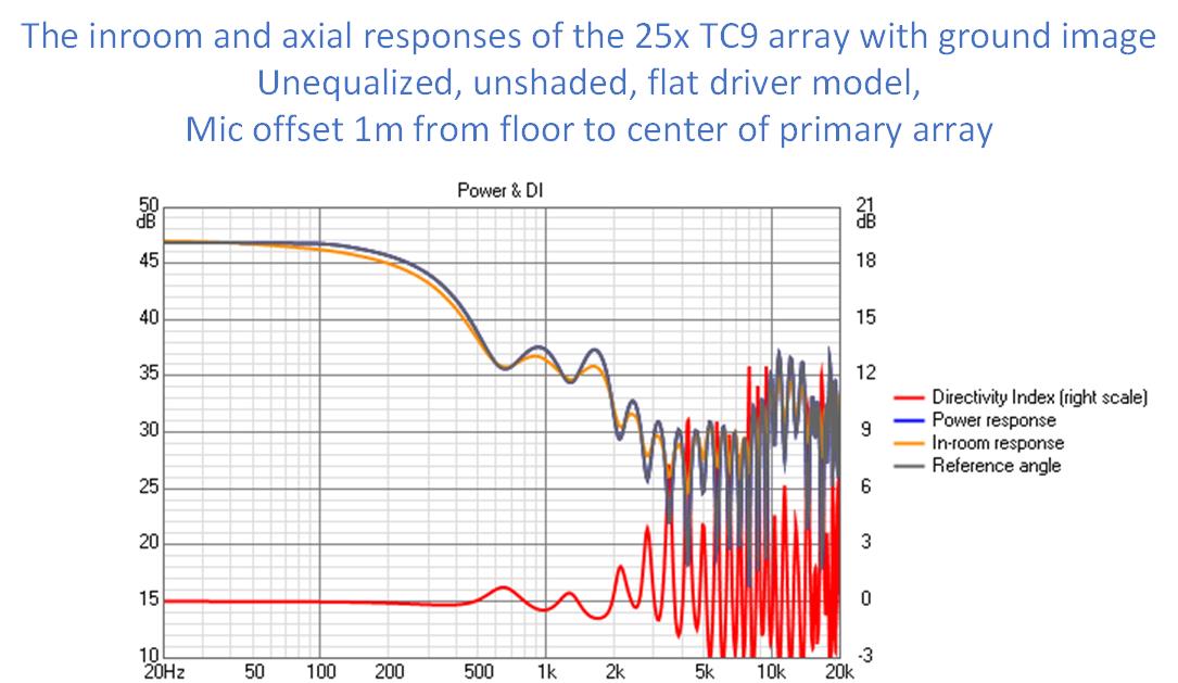
The true array center of the 2m high physical array being modeled is now 1m above the virtual floor, which Vituix treats as array center. Therefore, I set the microphone offset to 1m and used the room response as simulation reference.
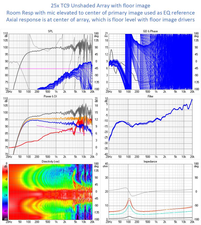
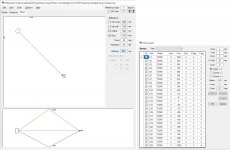
This worked as you can see in the nicely flattened orange trace in the middle graph. In the next picture, I've pulled responses into Vituix for a better look:
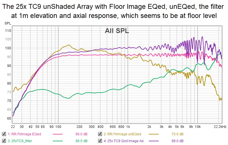
The flattest trace is of course the equalized room response. The downward slanting gold trace is the un-equalized room response, which looks more like a real measurement than anything else I've produced. The dark purple trace is the axial response which apparently is at virtual floor level. The green trace is the filter itself created by IR inverting a 6th octave smoothed version of the unequalized room response.
What about the ceiling image drivers. Including them seems to break Vituix. I'm still investigating how badly and looking for the maximum number of drivers I can include and still get sensible results.
Its taken me a while to add the floor image drivers, sort through various pilot errors, and figure out what I'm looking at.
The first thing I saw was increased combing, which is only to be expected given that now there are twice as many drivers combining, half of them from greater distances. That dampens my enthusiasm for the frequency shading because the image responses will be delayed enough for destructive combining even though the direct sound is not. But that frequency shading may be useful for a half ceiling height array shaded so delayed floor and ceiling reflections don't pass 90 degree phase shift.
The true array center of the 2m high physical array being modeled is now 1m above the virtual floor, which Vituix treats as array center. Therefore, I set the microphone offset to 1m and used the room response as simulation reference.
This worked as you can see in the nicely flattened orange trace in the middle graph. In the next picture, I've pulled responses into Vituix for a better look:
The flattest trace is of course the equalized room response. The downward slanting gold trace is the un-equalized room response, which looks more like a real measurement than anything else I've produced. The dark purple trace is the axial response which apparently is at virtual floor level. The green trace is the filter itself created by IR inverting a 6th octave smoothed version of the unequalized room response.
What about the ceiling image drivers. Including them seems to break Vituix. I'm still investigating how badly and looking for the maximum number of drivers I can include and still get sensible results.
Attachments

In all honesty I think this FR plot is pretty close to reality. Did you apply some sort of absorption in the reflection properties? I'd believe we wouldn't get a true floor reflection but that it would be somewhat reduced in level. Not sure how much it would be reduced though.
Not sure why the vertical directivity is upside down from what I expected, but that may be due to the lengthened array with floor mirror? (missing the ceiling, thus having the symmetry (mid array) fall below the zero line)
What does it look like without floor reflection but with the 1m height position for equalising?
I think for a seated listening preference that shaded result looks pretty interesting too.
If one were to prefer a listening seat only setup it could prove to be worth investigating this further.
Can you show the other graphs belonging to this one?
And was this one done with passive means or linear phase LR like before.
Last edited:
- Home
- Loudspeakers
- Full Range
- Full range line array for wall or corner placement