A compelling case for shading
In his landmark article back in the day, Dave Smith made a compelling case for shading line arrays.
AES E-Library >> Discrete-Element Line Arrays-Their Modeling and Optimization
I reread the article recently and decided to give his simple 4 group shading a try in simulation.

Shading reduces the amount of frequency response ripple that needs to be equalized, which is good because that equalization is distance and position dependent.
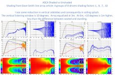
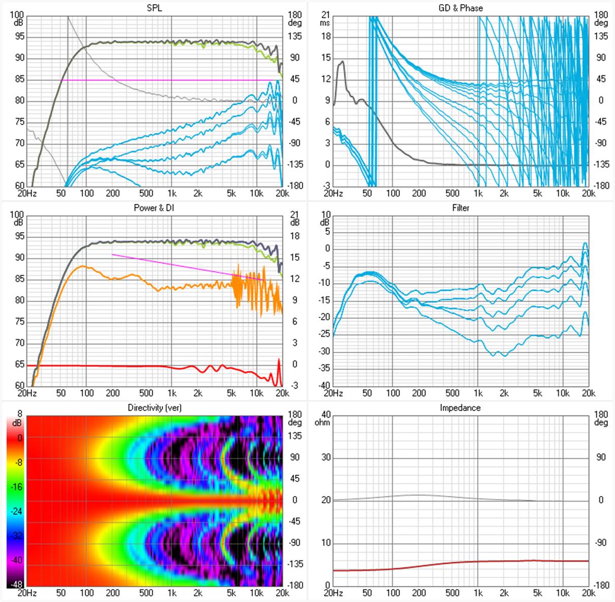
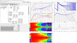
After I completed simulation models for both shaded and unshaded SB65 arrays, Vituix produced these graphs:
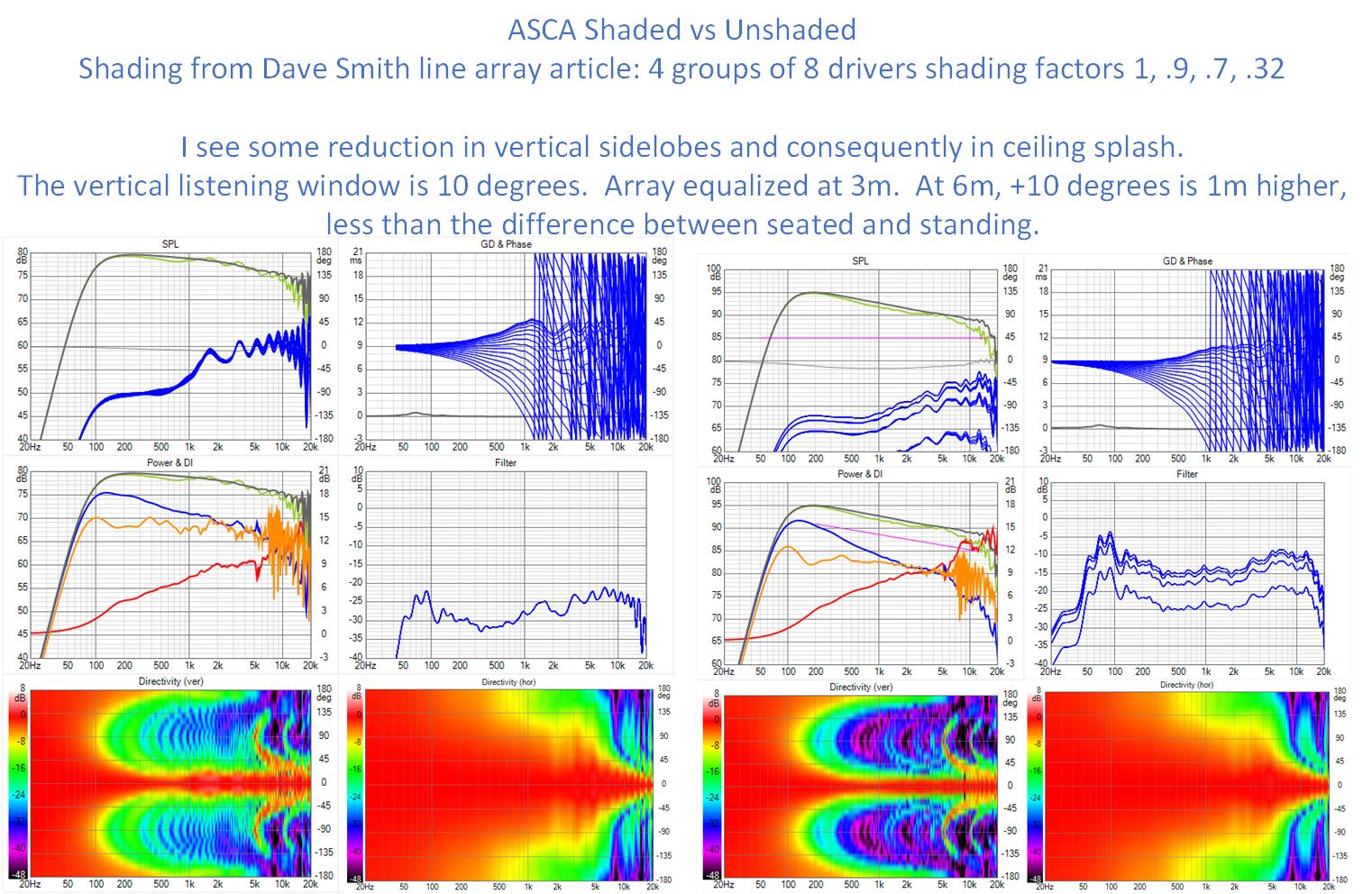
My usage model is seated at around 3-4m distance with standing futher back in the room. Thus I set the vertical listening window to 10 degrees, which covers this difference in ear height front to back.
The reduced ripple in the top octave allows me to get a smoother equalization result there (although it may be difficult to fully duplicate this result with in room measuments (understatement)). I also reduced vertical sidelobes and consequently less of what I earlier termed ceiling splash.
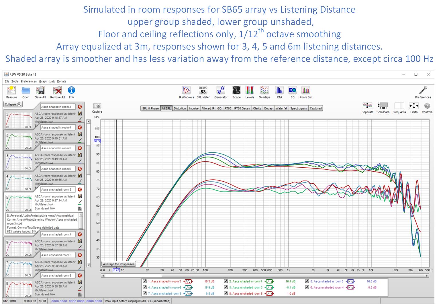
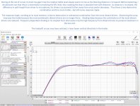
Next lets look at response variation with listening distance and then mic/ear height:
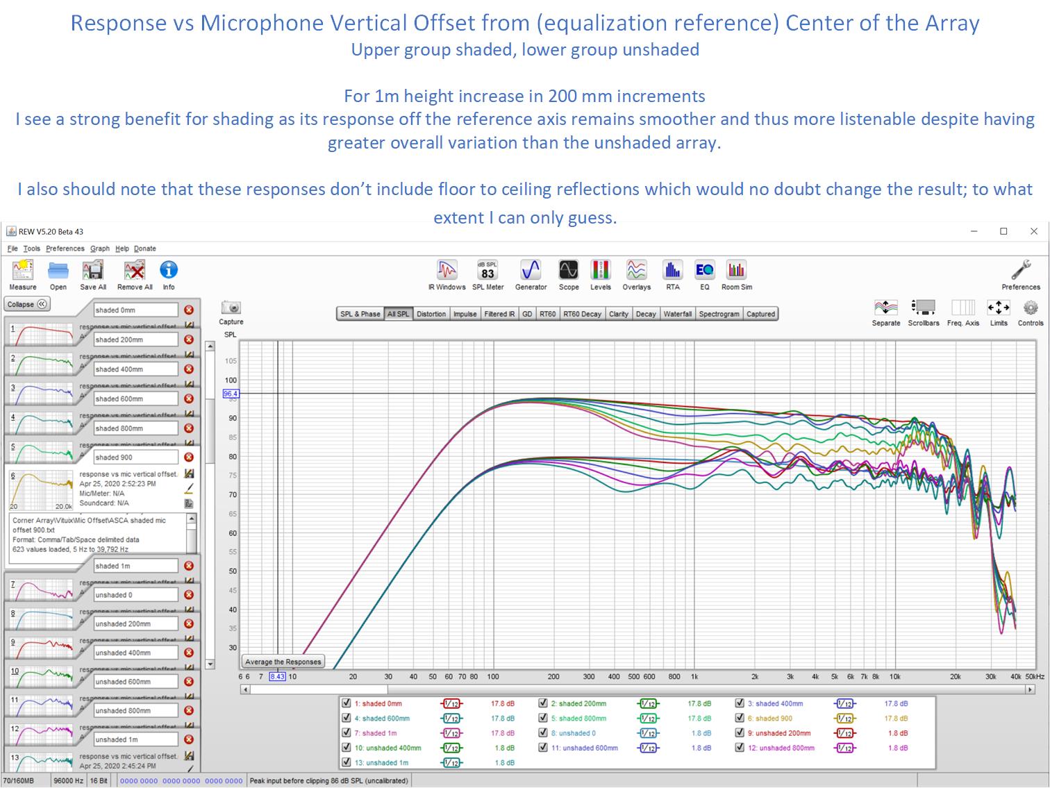
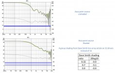
and finally those comb lines that cause so much concern but which disappear under smoothings that attempt to mimic human hearing:

For the shaded array at my primary listening distance, 2 db pk to pk ripple remains fom 12 khz up due to equalization limitations but there is only a single true combing null and that at 17.5 khz!
Several (many) of us have built unshaded floor to ceiling line arrays relying on floor to ceiling reflections to provide performance approaching that of an infinite line array. We've measured these in room and seen more variation that perhaps expected under the infinite line array model. Some of that is undoubtedly due to the room but a lot of it is due to the discrete nature of these arrays. If simulation can prove anything, its proven that shading a discrete line array can reduce that part of the positional variation.
If you have a single listening distance (e.g. multiple seats on a couch) then I think you can get away without shading. For any other situation, I think shading will have significant benefits.
In his landmark article back in the day, Dave Smith made a compelling case for shading line arrays.
AES E-Library >> Discrete-Element Line Arrays-Their Modeling and Optimization
I reread the article recently and decided to give his simple 4 group shading a try in simulation.
Shading reduces the amount of frequency response ripple that needs to be equalized, which is good because that equalization is distance and position dependent.
After I completed simulation models for both shaded and unshaded SB65 arrays, Vituix produced these graphs:
My usage model is seated at around 3-4m distance with standing futher back in the room. Thus I set the vertical listening window to 10 degrees, which covers this difference in ear height front to back.
The reduced ripple in the top octave allows me to get a smoother equalization result there (although it may be difficult to fully duplicate this result with in room measuments (understatement)). I also reduced vertical sidelobes and consequently less of what I earlier termed ceiling splash.
Next lets look at response variation with listening distance and then mic/ear height:
and finally those comb lines that cause so much concern but which disappear under smoothings that attempt to mimic human hearing:
For the shaded array at my primary listening distance, 2 db pk to pk ripple remains fom 12 khz up due to equalization limitations but there is only a single true combing null and that at 17.5 khz!
Several (many) of us have built unshaded floor to ceiling line arrays relying on floor to ceiling reflections to provide performance approaching that of an infinite line array. We've measured these in room and seen more variation that perhaps expected under the infinite line array model. Some of that is undoubtedly due to the room but a lot of it is due to the discrete nature of these arrays. If simulation can prove anything, its proven that shading a discrete line array can reduce that part of the positional variation.
If you have a single listening distance (e.g. multiple seats on a couch) then I think you can get away without shading. For any other situation, I think shading will have significant benefits.
Attachments
Thanks for that analysis. Very interesting.
In my own investigations, I found that comb filtering was not an issue as long as you are at least 1.5 to 2 times away from the array as the length of the array. See posts beginning #127 here:
Corner Floor-to-Ceiling Line Array Using Vifa TC9
My conclusion was it was good enough without shading if you are far enough from the array. The summation starts becoming random at frequencies where the individual drivers are too big if you are far enough from the array. So, you don't get exact peaks and nulls because there are too many drivers.
Apart from the combing, however, my recent investigations with dedicated tweeters have shown that there is definite improvement to be had with a dedicated tweeter. In keeping in that vein, I want to experiment with an expanding array where the elements would roll off depending upon their distance from the center of the array. So, like shading, but instead of using resistors, it would be inductors. The outermost elements would roll off earlier and only two elements would be operating before the crossover to a single tweeter.
Hi Ra7:
My conclusions are consistent with yours. For a single listening distance of at least 3m or so, comb filtering isn't a problem and thus no shading needed. I didn't state the "at least 3m explicitly" but that should be apparent from my simulations as well as from your measurements and my use of 3m as the equalization reference.
I was seeking a deeper understanding of discrete line arrays with these simulations. Let me summarize as follows: Summing responses of individual drivers as opposed to having a single continuous line source leads to a frequency response ripple of increasing frequency as frequency rises ultimately leading to actual comb filtering as we go higher in frequency at a fixed listening distance. Comb filtering being the point where you see nulls in the response as opposed to mere rounded bottom dips. In the midrange at least, those dips can be equalized away but that equalization is position dependent so if your usage model includes multiple listening distances or heights, then shading will yield a benefit. Shading reduces that frequency response ripple but it also reduces the vertical sidelobes at high frequency where the array has lost vertical directivity control where the driver spacing is too high for the frequency. Reduction in vertical sidelobes reduces what I've called ceiling splash: scattering of HF off the ceiling and floor, whose reflections will be arrive at the LP with delays of probably less than 10 ms. I doubt these matter to perception but they might have a second order effect.
I hope that isn't too pedantic.
I'm very familiar with your thread, downloaded your measurements quite a while ago, and studied them while doing my initial array design. It was good to re-read portions of it again this morning. I recall you did an expanding array of a relatively small number of large(r) drivers before your TC9 array so I'm not surprised you are planning a move back in that direction.
What are your goals with that central tweeter or super tweeter? Better treble or treble dispersion than an array of full range drivers can provide? I can understand that having spent a fair amount of time looking for suitable ribbon or planar line sources and having lived with a Carver Amazing Platinum Edition (with 5' long ribbon) for a couple of decades back in the day. Do you expect that fine step expanding array to do a better job of smoothing out the full range array's frequency response ripple than does simple shading schemes? I imagine the kind of simulations I've been doing could at least answer that question.
What are your goals with that central tweeter or super tweeter? Better treble or treble dispersion than an array of full range drivers can provide? I can understand that having spent a fair amount of time looking for suitable ribbon or planar line sources and having lived with a Carver Amazing Platinum Edition (with 5' long ribbon) for a couple of decades back in the day. Do you expect that fine step expanding array to do a better job of smoothing out the full range array's frequency response ripple than does simple shading schemes? I imagine the kind of simulations I've been doing could at least answer that question.
Wow, didn't know you were following along on the other thread. Yes, better treble definition and imaging than is possible with an array of TC9s. As good as that driver is, a dedicated tweeter is just better at reproducing those frequencies with more finesse. I tried out the Fountek ribbon and it was a revelation. I recently tried out a small 5-element array of the Peerless OC25 and they weren't as good. The Fountek ribbon has a small horn in front of it that gives a closed in, headphone like feel to the sound, at least until you get used to it. I imagine it pushes more direct sound relative to the reflected sound compared to just the TC9 array. That in turn results in better imaging. While the 5x OC25 experiment wasn't so successful, I want to try with at least one OC25 crossing to two TC9s and then expanding beyond that, just to see what that does. If you have sims, would love to see'em.
I haven't simmed anything with a central tweeter....yet. I will put that on my list because it is interesting. I don't know how well I can synthesize directivity for a dome tweeter but a flat piston or a rectangular planar is no problem. The waveguide on the Fountek would be an issue but if you had 10 degree directivity data I could import it. I can certainly do something with a generic piston or diaphragm shape to get a feel for it.
I've been developing a concept of the Dayton PTmini-6 coaxial with diameter matched TC9 that shows promise but too early to share. Tthe Mini has same size radiating surface as one of the Founteks I looked up but not the power handling. OTOH you can stack them in line as tall as you want.
I've been developing a concept of the Dayton PTmini-6 coaxial with diameter matched TC9 that shows promise but too early to share. Tthe Mini has same size radiating surface as one of the Founteks I looked up but not the power handling. OTOH you can stack them in line as tall as you want.
Last edited:
In his landmark article back in the day, Dave Smith made a compelling case for shading line arrays.
AES E-Library >> Discrete-Element Line Arrays-Their Modeling and Optimization
I reread the article recently and decided to give his simple 4 group shading a try in simulation.
Surprising, as I do remember reading this quote by Dave Smith:
Some comments: If you are doing a long array, nearly floor to ceiling, then run all your units full strength in a series parallel arrangement. For mid length arrays, say 2 to 4 feet long, I would strongly recommend a level tapering scheme along the array's length, otherwise the frequency response will vary strongly with listener height. If you go shorter, then a progressive crossover scheme (tweeter in the center and additional elements coming into play as you go down the frequency range) is the way to go. In the end you want the array's effective length to grow in proportion to wavelength.
Regards,
David S.
😛 Just teasing here, although I have often though of frequency depended shading in our line arrays, I've never really tried it due to wanting to hold on to the Infinite line theory. And the positive results by using and finding the best way to fight its drawbacks at the listening spot.
I still think we need relative long FDW windows up top in our DSP (at high frequencies) to get the most out of these arrays. I've tested that for months (literary) to find the proper balance of these windows. It made a huge difference in perception, even though it was hard to find big differences in measurements.
I'm not against shading, however only used in a frequency dependent way. Keeping as much advantages of the array as possible. Should be interesting to test this.
I might do it myself if I ever get around to it. I'm still way behind on many other tasks I want to do or try first 😀.
Among which is the use of ambient tweeters...
Last edited:
well if you are teasing there isn't anything to argue about. Too bad, it would have helped pass pandemic time.
We know our floor to ceiling arrays aren't effectively infinite because of the variation with height and listening distance that we see. My simulations show some improvement with shading even for nearly 8' tall arrays. Adding shading is lots less effort than an entirely new project.
What about that expanding array? Too many choices within that concept to just draw it up. But ra7 hinted essentially a tapped inductor with a driver(s) at each tap for the array. This narrows the choices. One can't just put a tweeter in the center without a small waveguide to match its directivity to that of the array because that would ensure a directivity mismatch at the crossover. One could simulate that expanding mid bass array to derive directivity requirements for that waveguide. Perhaps a shallow OS shape with diameter matched to the woofer cone CNCed into the (thickened) baffle.
Yeah, I’ve thought about the pt mini but the power handling is poor and you cannot cross it low it enough before the tc9s start beaming. The plan with the oc25 was to cross around 1500 hz but even with 5 of them, it proved too low. That was the drawback with the fountek too but it was still a phenomenal combination with the array crossed at 3 khz.
I am very curious to know how your synergy horns compare with the array. Tonal balance, while tricky, is largely within grasp with drc but imaging remains illusive for me. How do the horns compare with the areay in that aspect?
I am very curious to know how your synergy horns compare with the array. Tonal balance, while tricky, is largely within grasp with drc but imaging remains illusive for me. How do the horns compare with the areay in that aspect?
I agree that power handling is the mini's weak spot. 8++ drivers and array rolloff seems to cancel the gain in efficiency from adding more drivers but does add power handling. On top of that, it rolls off 7 db from 10 khz to 20 khz. Nevertheless, I think it is robust enough for in home use.
Start with 90 db at 1W from the data sheet
+10db for 10W,
+9 db for 3 power doublings to 8 drivers or 16 drivers with shading,
-3 db for array ripple eq in top octave,
-7 db for device rolloff from 10 khz to 20 khz, less with hearing limitations
+7 db for room curve
= 106 db if it sounds good at 10W per driver
Even 1W per driver should suffice for my needs. I need a test box listen to confirm.
The TC9's response can be widened up to 6 khz or so by playing through a tapered slot. TC9 on rear of baffle, mini on front so they overlap for tight CTC.
As to array imaging vs synergy. @Mark100 raves about his 48"x29" synergy and its imaging. I truly liked mine. It had a sweet top end and excess SPL capability all the way down but it suffered from an unterminated mouth, floor and ceiling bounce, and being a corner speaker, would have benefited from ambience drivers. I could not get clean measurements at the LP in that mostly untreated room. I know I didn't match left to right response closer than a db or so, if that. My attention was on other things.
I wouldn't describe my synergy as having bad imaging but the imaging of my arrays placed well out into a larger room presented a 3D soundscape that at times literally blew me away. I had lots of treatment in the garage and got clean measurements at my LP there, except for some trouble around 200 Hz.
One of these days, I'll get both systems optimized and set up simultaneously and be able to do a meaningful comparison.
Hi Jack, told ya i was keeping an eye on this thread 🙂
I can't really comment yet, on how well the big syn images (in stereo), because so far I've only built one.
In mono though, it has the most gripping sense of realism i think i've heard yet. Makes a killer soundstage in the horn...
Can't wait to get the other built and hear stereo....
The MTM's that I've built around coax CD's sound pretty close to the different synergies, as in a similar point source sound. They image better in stereo that my arrays did, on most music. But not on all. The more room ambience, or reverb, in a recording, the more I think I like the wider dispersion arrays. I don't think the point sources do as convincing a job with depth-like info, as wider pattern speakers, even omnis. Just my impressions....
In my old audiophool days, I valued imaging above all, which I found with electrostats. It strikes me funny that they are really just a wide line array, with near crazy vertical HF/VHF directivity, and with dipole directivity down low and mid. (3 panel Acoustat X at least)
A reminder how little i know still ...
One thing i do believe about imaging however, is symmetry is key.
Two cheap anythings, perfectly symmetrical in room response, have always imaged surprisingly well ime
Good to hear from you Mark. Well that other horn won't build itself 🙂 its not like cranking out an new array configuration simulation in a few minutes to tens of minutes.
re' point sources: I found it hard to conceive of a point source that wouldn't have boundary issues in room - but a 48" x 29" horn is getting there. If its too directive you can add ambience speakers. If you have the room for large point source horns, I have to believe they are the way to go.
Arrays are the first thing to consider when you don't.
Thx !
You're gonna laugh, but it's not building the actual second synergy that's the holdup. I honestly think i can crank it out in a single day.
It's these damn foamboard flares that take the horn out to 48 x 29 inches.
Pushing 48" wide foam through a hotwire table, to make the tractrix-like curvature, has been an adventure to say the least. You should see the foamboard scrap pile 😱
And now, learning to epoxy and lay glass cloth on them....YIKES !
I'm simply not used to dealing with the sloppy tolerances I keep getting.
My garage is now set up entirely for foamboard,.....4x8ft dead-level table for the sliding table hot wire foam cutter i conjured up....
and also as a pitiful try at a clean room for the epoxy process.
Can't start the second syn till I finish these cursed foam flares for both syns. 🙁
I was telling my son yesterday....i think it would be easier to build the foam flares first, and then match to wood synergy horn to THEM
re boundary issues....once above Schroeder, i rely more on the direct to indirect sound ratio, than trying to handle boundary issues.
It's cause I move stuff around so much, and am always running at least two systems in same room. So for me, I like high directivity.
The 60x40 syn I built that is too heavy to move, has close to the same mouth size as the current 90x60. I think the 60x40 sounds slightly more engaging.
I've also liked the 60 builds of my MTMs better than the 90 deg versions. But that could just be the 60 deg xt1464 is a better horn than the 90 deg hf950 ...dunno
Besides, I'm not much of a fan of reverberate-field, type music.
Back to horses for courses, and preferences, as always, huh 🙂?
Well good luck with the flare construction. That sounds like too much aggravation for me. It also sounds like it will be worth effort in the end.
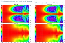
We had a brief discussion a few days ago about an array with a central tweeter. I did a sim of my developing PTmini coax array with a central tweeter as a quick experiment.
I repeated it with the planar mini replaced with a 1" full range driver acting as a tweeter.
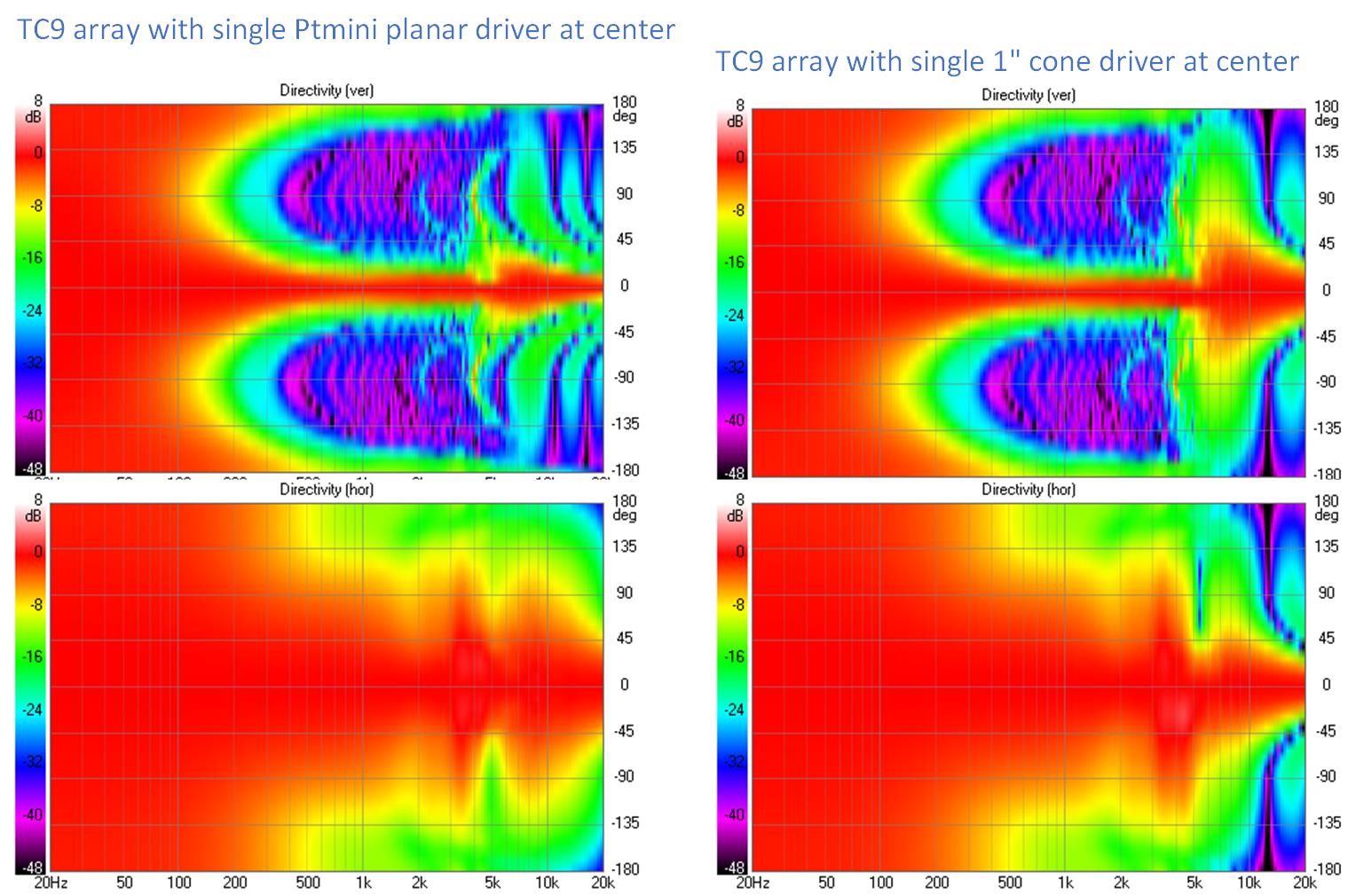
The thing you can say about the planar tweeter at center is that the vertical beam is very narrow. The tweeter would need to be at ear height and
a single tweeter would be too restrictive, head position wise. So how tall should the planar tweeter array be. More sims required to answer that question.
The 1" driver has a comfortably wider beam and a 3/4" tweeter would be wider still but then there is an abrupt change of polar shape at crossover. So the goal of the frequency weighted array would be to match to that directivity. Doing so with first order filters (e.g. inductors) brings time delay into the picture so that the frequency weighted array likely has some similarity to a CBT.
There is also a narrowing and an asymmetry of the horizontal polars at crossover. I think the asymmetry traces back to the tweeter being on one side of the woorer. The narrowing doesn't appear serious to me - its still 90 degrees wide and can thus fill a room from a corner. It might even be too wide for a small room. The TC9 array's horizontal directivity comes from playing through a slot that is 22mm wide. I could not go any narrower without restricting the bandwidth. The slot could be wider...
I repeated it with the planar mini replaced with a 1" full range driver acting as a tweeter.
The thing you can say about the planar tweeter at center is that the vertical beam is very narrow. The tweeter would need to be at ear height and
a single tweeter would be too restrictive, head position wise. So how tall should the planar tweeter array be. More sims required to answer that question.
The 1" driver has a comfortably wider beam and a 3/4" tweeter would be wider still but then there is an abrupt change of polar shape at crossover. So the goal of the frequency weighted array would be to match to that directivity. Doing so with first order filters (e.g. inductors) brings time delay into the picture so that the frequency weighted array likely has some similarity to a CBT.
There is also a narrowing and an asymmetry of the horizontal polars at crossover. I think the asymmetry traces back to the tweeter being on one side of the woorer. The narrowing doesn't appear serious to me - its still 90 degrees wide and can thus fill a room from a corner. It might even be too wide for a small room. The TC9 array's horizontal directivity comes from playing through a slot that is 22mm wide. I could not go any narrower without restricting the bandwidth. The slot could be wider...
Attachments
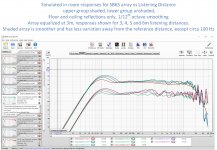
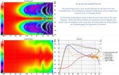
I think the very minimum planar tweeter height is 12" to cover the difference between sitting erect and sitting reclined. But that brings in concerns about how far the tweeter array will remain in nearfield and leaves little margin. 8 drivers gives an array height of just over two feet. Lets take a look at that:

Shading reduces the vertical sidelobes and resulting ceiling splash further at the cost of 3 resistors:
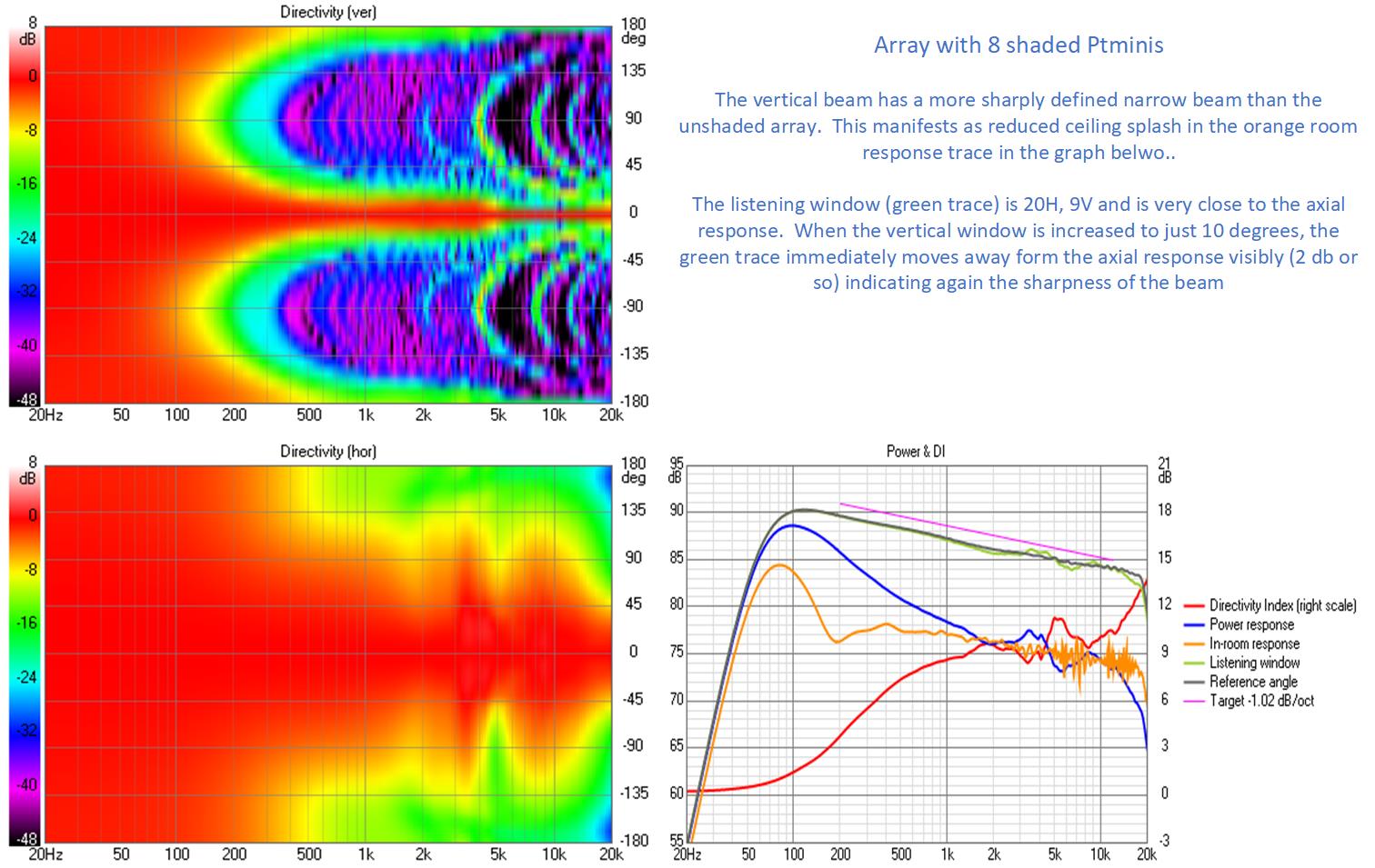
With 12 drivers, leaving off approximately 13" at top and bottom of the nearly floor to ceiling array we could cover sitting through standing ear height. I opted in the sim at least for 16 drivers for more margin at the high end:
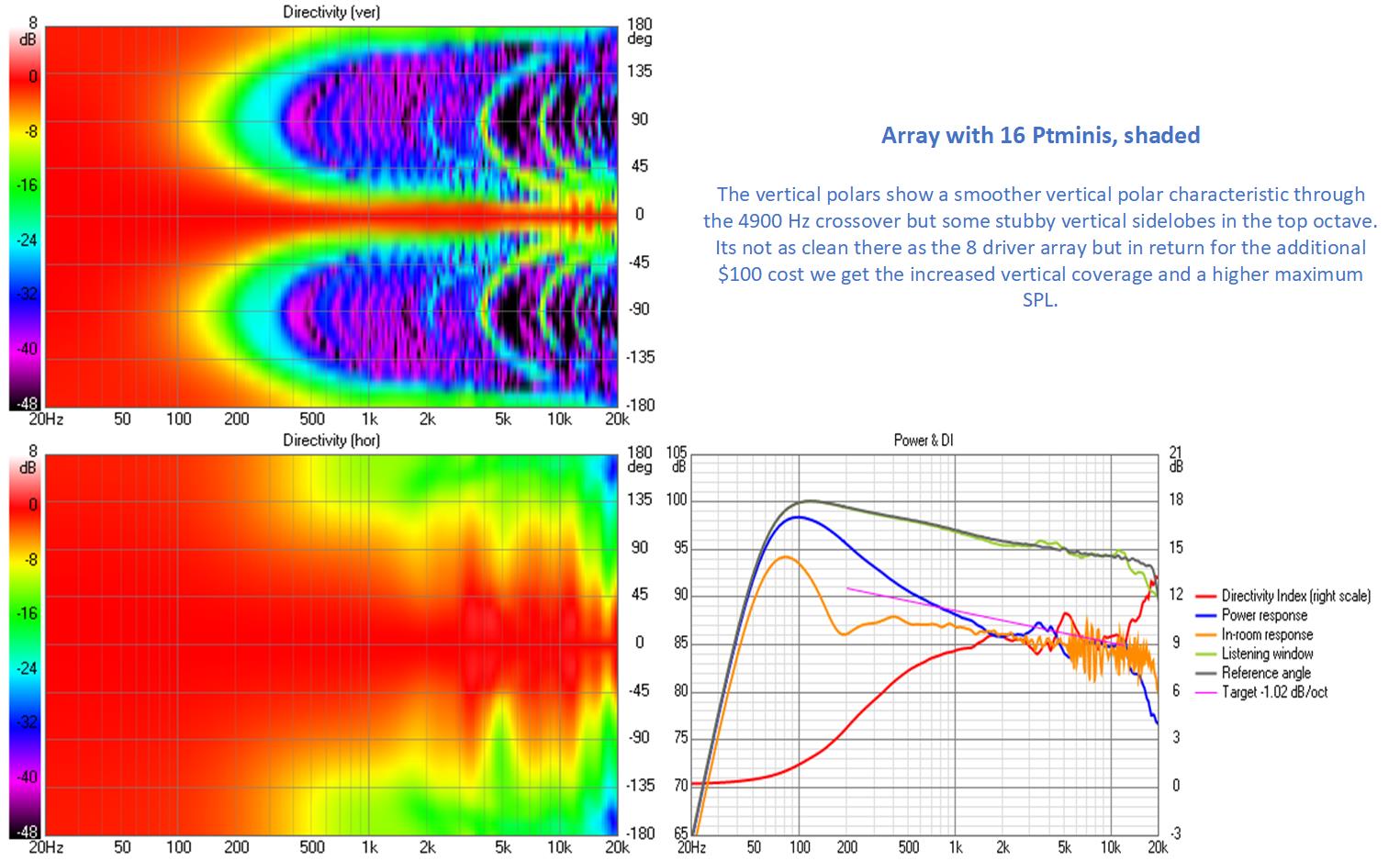
So the shorter array gives a cleaner top octave but the longer one has more SPL and wider vertical coverage. The former isn't unexpected - contributions from more distant tweeter elements usually don't help at high frequencies. One doesn't need to accept the tradeoff; one can make tweeter length configurable.
Shading reduces the vertical sidelobes and resulting ceiling splash further at the cost of 3 resistors:
With 12 drivers, leaving off approximately 13" at top and bottom of the nearly floor to ceiling array we could cover sitting through standing ear height. I opted in the sim at least for 16 drivers for more margin at the high end:
So the shorter array gives a cleaner top octave but the longer one has more SPL and wider vertical coverage. The former isn't unexpected - contributions from more distant tweeter elements usually don't help at high frequencies. One doesn't need to accept the tradeoff; one can make tweeter length configurable.
Attachments

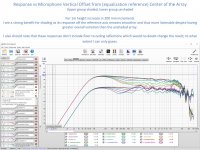
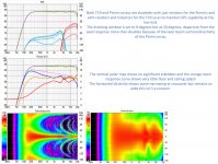
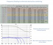
The question about tweeter array height can be made more simply and quickly looking at point source simulation results:
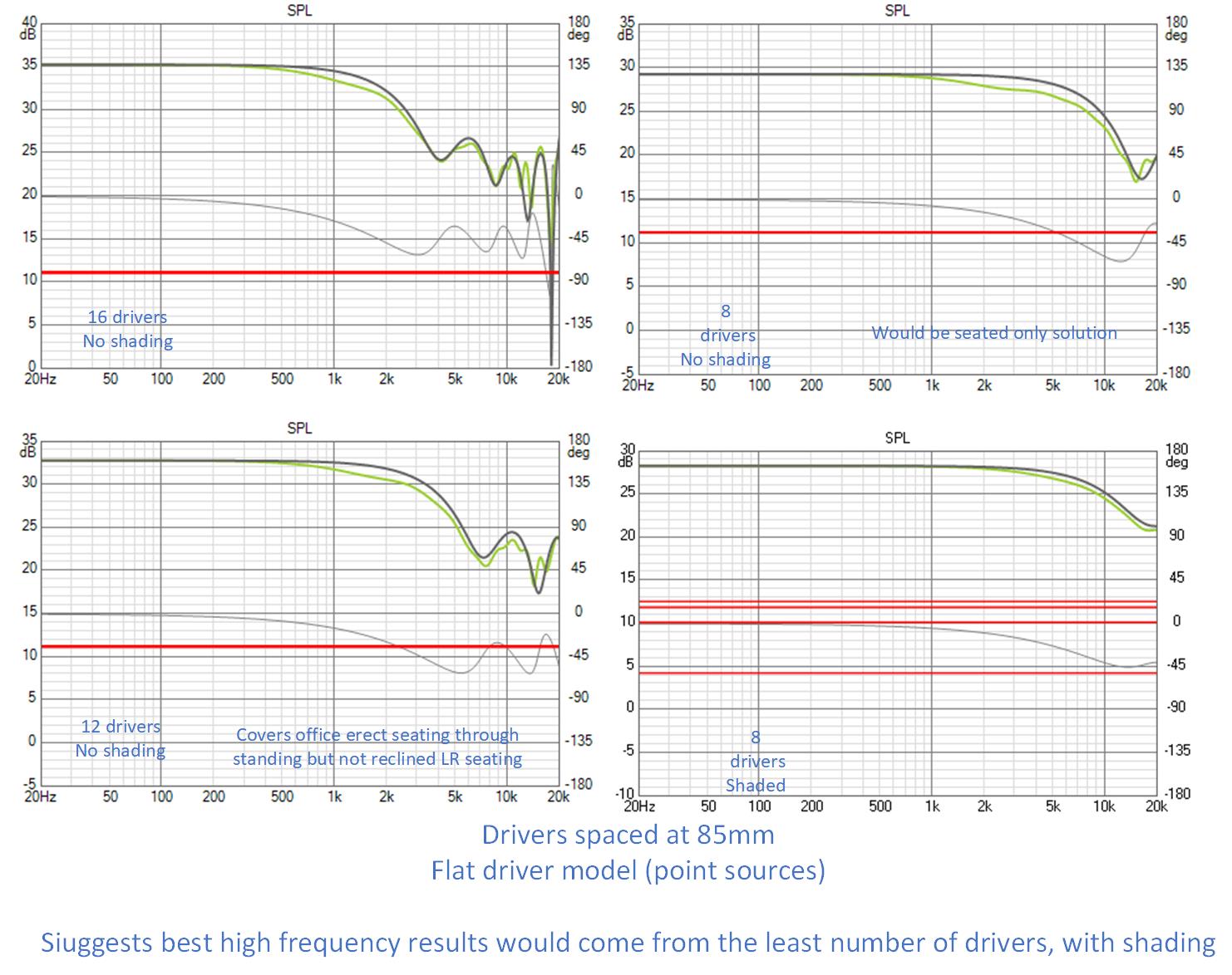
The frequency response ripple in these graphs is entirely due to destructive combination from the more distant drivers. This slide clearly says that the shorter the array the better, at least in that respect.
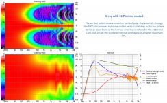
Now put that 8 tweeter array coaxial with an equal number TC9s, extend the TC9s to floor and almost ceiling and equalize:
What are the consequences of that short tweeter array. I'll have to check how far away it will remain in the nearfield but first let's look at the response vs listening distance:
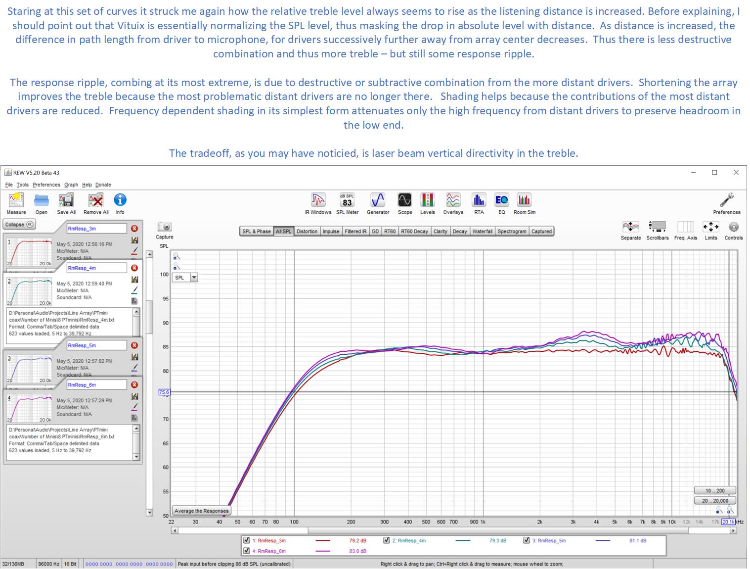
I hope the text on the slide wasn't too much of an eye test. To summarize, it says that at longer distances we get less delta path length from drivers progressively further out on the array and its that delta path length that is the root of all evil in the treble.
The remaining bugaboo is the vertical directivity. As the next slide shows, one will want the center of this short treble array within a couple of inches of ear height.

The frequency response ripple in these graphs is entirely due to destructive combination from the more distant drivers. This slide clearly says that the shorter the array the better, at least in that respect.
Now put that 8 tweeter array coaxial with an equal number TC9s, extend the TC9s to floor and almost ceiling and equalize:
What are the consequences of that short tweeter array. I'll have to check how far away it will remain in the nearfield but first let's look at the response vs listening distance:
I hope the text on the slide wasn't too much of an eye test. To summarize, it says that at longer distances we get less delta path length from drivers progressively further out on the array and its that delta path length that is the root of all evil in the treble.
The remaining bugaboo is the vertical directivity. As the next slide shows, one will want the center of this short treble array within a couple of inches of ear height.
Attachments


Shading TC9 Arrays
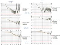
Given the large number of TC9 arrays in the world, it would be remiss of me not to explore shading them.
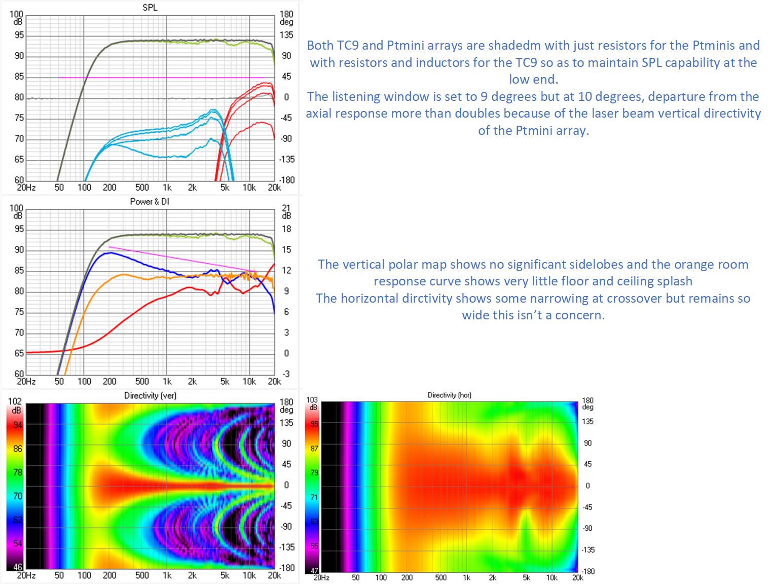
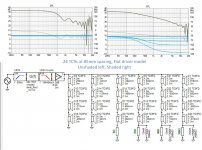
The simplest shading uses resistor weighting to reduce contributions of distant elements then parallels resistors with inductors to get back the displacement capability at the low end of the frequency range:
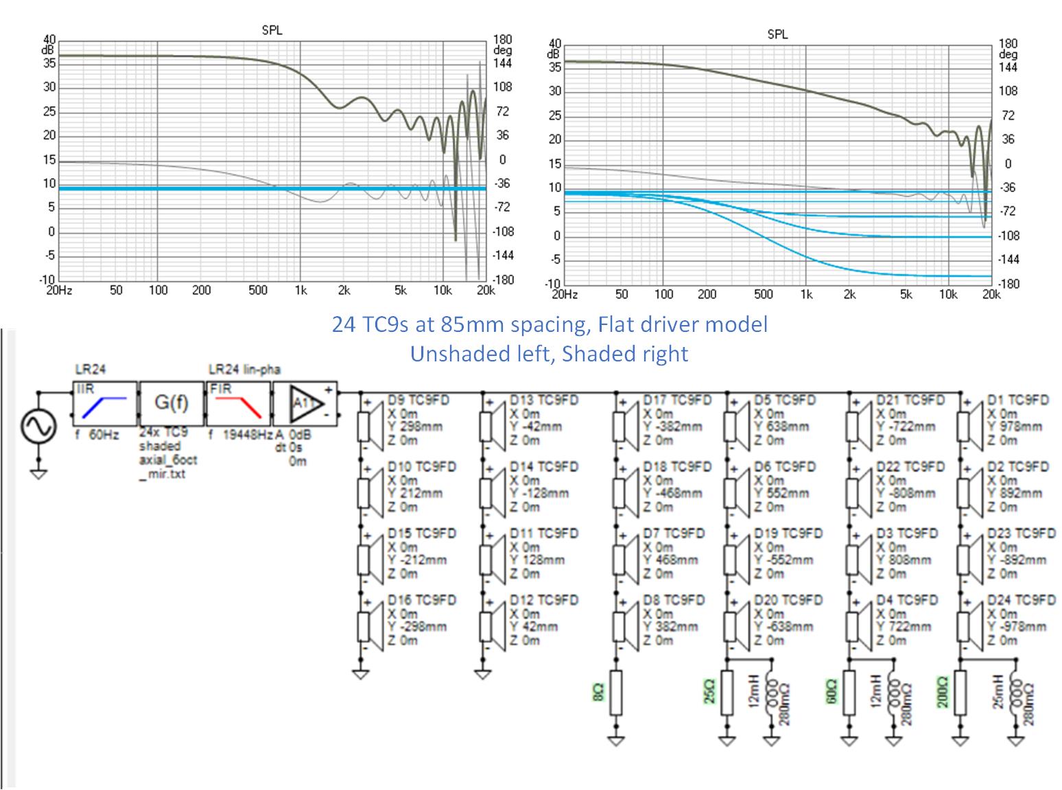
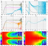
This simple shading reduces the frequency response ripple but doesn't eliminate it. Full simulation results for shaded and unshaded follow:

the above is unshaded, below is shaded:
Given the large number of TC9 arrays in the world, it would be remiss of me not to explore shading them.
The simplest shading uses resistor weighting to reduce contributions of distant elements then parallels resistors with inductors to get back the displacement capability at the low end of the frequency range:
This simple shading reduces the frequency response ripple but doesn't eliminate it. Full simulation results for shaded and unshaded follow:
the above is unshaded, below is shaded:
Attachments

As I see it , you are going to loose a lot of sensitivity this way. Maybe the cure is worse than the illness?Given the large number of TC9 arrays in the world, it would be remiss of me not to explore shading them.
The simplest shading uses resistor weighting to reduce contributions of distant elements then parallels resistors with inductors to get back the displacement capability at the low end of the frequency range:
This simple shading reduces the frequency response ripple but doesn't eliminate it. Full simulation results for shaded and unshaded follow:
the above is unshaded, below is shaded:
- Home
- Loudspeakers
- Full Range
- Full range line array for wall or corner placement