Well its been a long time since I posted. Since then I've moved and haven't gotten the arrays back up. To keep myself busy lately I've been doing some simulation/analysis and a couple of paper designs i may never build.
I would like to share some of this so here goes
I would like to share some of this so here goes

We are left with at least two questions:
what about that combing; is it audible?
would this equalization method work as well in practice as it does in simulation?
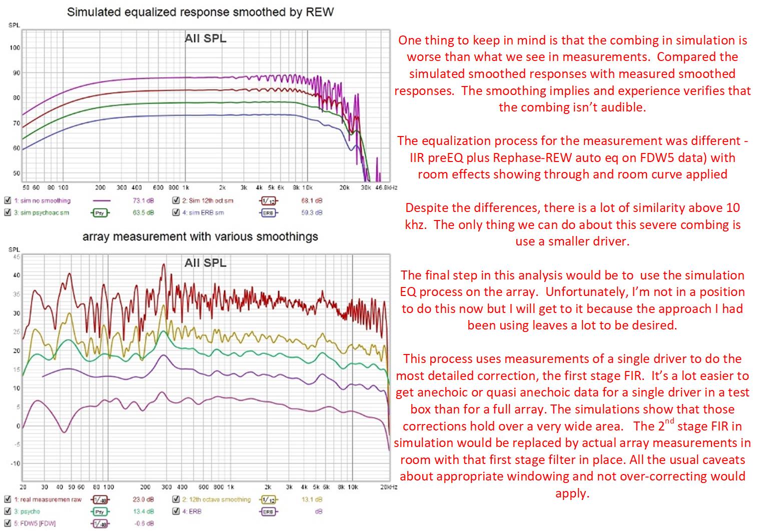
Well I too don't believe the combing is audible but I can't help thinking the SQ would be better without it - so I'm going to take another look at CBT and at smaller drivers.
As to the eq method, I'm excited to try it. My old method of laborious manual pre-eq followed by Rephase REW semi-auto-EQ took way too long and didn't work as well as I would like. This method with a detailed driver eq on data one has taken special care to ensure the cleanliness thereof followed by a room eq of the full array shows a lot of promise.
what about that combing; is it audible?
would this equalization method work as well in practice as it does in simulation?
Well I too don't believe the combing is audible but I can't help thinking the SQ would be better without it - so I'm going to take another look at CBT and at smaller drivers.
As to the eq method, I'm excited to try it. My old method of laborious manual pre-eq followed by Rephase REW semi-auto-EQ took way too long and didn't work as well as I would like. This method with a detailed driver eq on data one has taken special care to ensure the cleanliness thereof followed by a room eq of the full array shows a lot of promise.
Attachments
Why not try DRC-FIR for correction? I've never been able to get better results than to start with DRC-FIR. No manual correction has ever been better and believe me I tried.
What I'm missing here is variation in window lengths. The REW Frequency Dependent Windows are not very detailed compared to same length windows used in DRC. On top of that you can vary the window length of the correction throughout the frequency spectrum, which is very useful up top with arrays.
What I'm missing here is variation in window lengths. The REW Frequency Dependent Windows are not very detailed compared to same length windows used in DRC. On top of that you can vary the window length of the correction throughout the frequency spectrum, which is very useful up top with arrays.
Last edited:
But you don't start with DRC - you do some pre-EQ to start. DRC then does its thing, being careful not to overcorrect and to exclude the room and with a lot of hand holding and tuning from you.
What I'm showing here is that a detailed correction on the anechoic or quasi anechoic response of a single driver should be part of that pre-eq. I doubt you could ever get DRC to do such a detailed correction yet I've seen in simulation at least, that that correction holds over a wide listening window and therefore is a good thing to do. It plus an HF shelf at least gives you something to listen too while you are trying to get DRC to work🙂
I didn't come right out and say it when I mentioned some form of room eq for the 2nd stage FIR in the process I described but I was thinking perhaps DRC. I think though that you would have to include that HF shelf filter to flatten the array rolloff before applying DRC.
I have tried DRC several times and its always frustrated me. That might say more about the room and level of room treatment or about me than it does about DRC. But if I can find the magic without using DRC, that is how I'm going to go.
The next several posts will go through same set of slides but for a 24 element CBT. Surprisingly, the CBT simulation doesn't show that "wildness" in the top octave that we see in the straight line array. As a result, equalization at the high end is much simpler (and as regards, DRC has no apparent need for tunable windowing there). You may recall that Jim Griffin just used the auto-EQ in his AVR for his CBT.
What the CBT does apparently suffer from is some peaking in the upper midrange/lower treble well off axis which may be addressable through weighting.
What the CBT does apparently suffer from is some peaking in the upper midrange/lower treble well off axis which may be addressable through weighting.
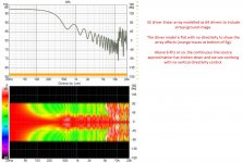
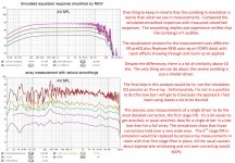
now for the first stage equalization. Take out the driver response variations and you are left with the array effects: roll off and ripple
Wow! The strong combing above 10 khz we saw with the same driver in a straight array doesn't appear here.
In fact, we could get pretty close to a finished result with an HF shelf filter and a couple of PEQs, but IR inversion with the appropriate windowing will get there quicker and more accurately ( or a shelf plus DRC, which also does IR inversion with sophisticated FDW)
Attachments
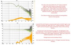
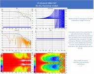
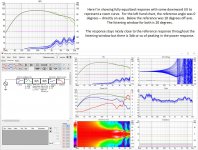
2nd stage IR inversion EQ with response shaping on both ends of the spectrum
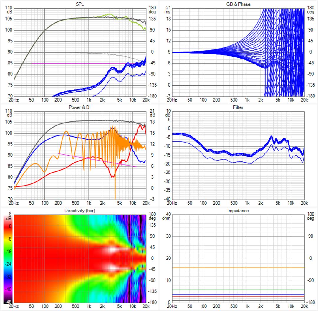
The listening window is set to +/-20 degrees to avoid the upper midrange blooming that has been mentioned. Next post I'll show responses for wider windows.
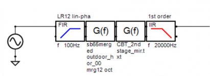
This is the all the eq I'm using but that is because there is no room to contend with:

that final LPF should be higher order...
The listening window is set to +/-20 degrees to avoid the upper midrange blooming that has been mentioned. Next post I'll show responses for wider windows.
This is the all the eq I'm using but that is because there is no room to contend with:
that final LPF should be higher order...
Attachments
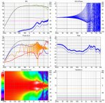
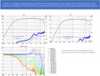
a look further off axis...
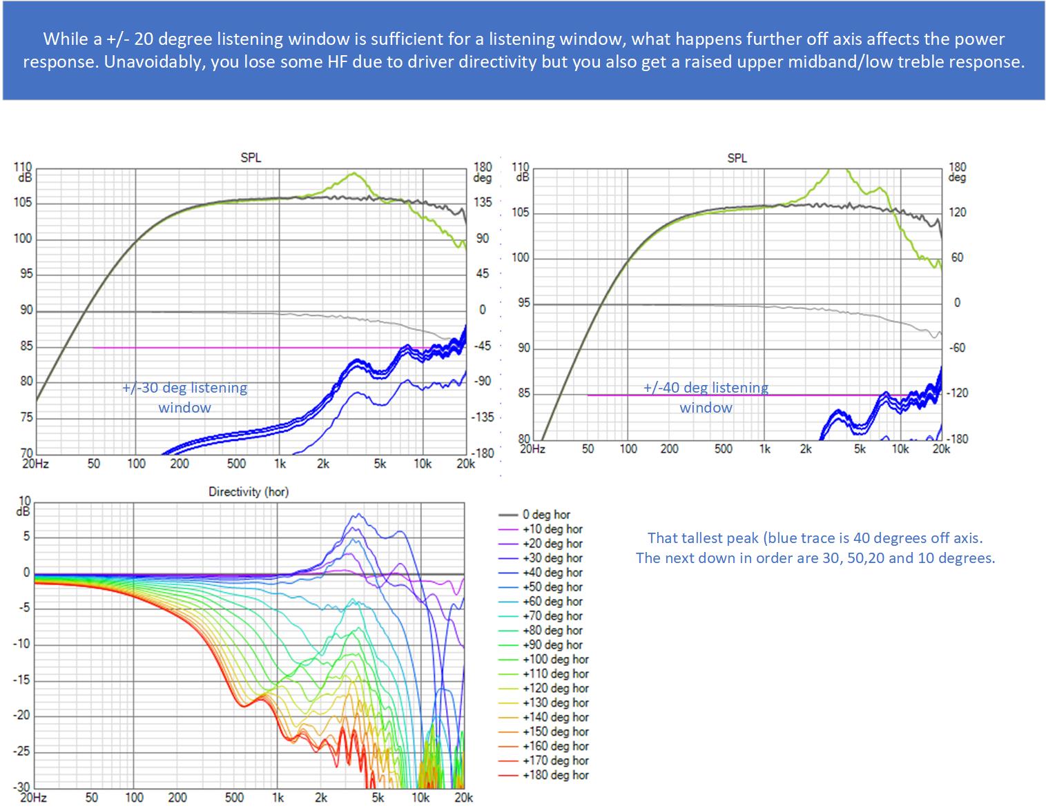
Do we really care what happens so far off axis? Probably not at home but perhaps we would at a live music event if our CBT could play loud enough for pro sound use. I've played with the weights enough to know I can improve the off axis response at least incrementally. Strangely, adding delays to the outermost drivers had a significant effect.
Do we really care what happens so far off axis? Probably not at home but perhaps we would at a live music event if our CBT could play loud enough for pro sound use. I've played with the weights enough to know I can improve the off axis response at least incrementally. Strangely, adding delays to the outermost drivers had a significant effect.
Attachments
But you don't start with DRC - you do some pre-EQ to start. DRC then does its thing, being careful not to overcorrect and to exclude the room and with a lot of hand holding and tuning from you.
Pré-EQ is there for one reason and one reason only. To get the raw output within the DRC-FIR scope of correction. It does not matter if I use precise pré EQ or global. The end result will pretty much be the same.
I think you have the wrong idea about my DRC experiments. While I do look for possible improvements, my DRC stage is not that experimental. However there is more to this game than that correction step alone. Setting the balance right is time consuming and I wouldn't automate it ever. But much of my DRC template has not changed in years, except for a couple of experiments I did recently.
What I'm showing here is that a detailed correction on the anechoic or quasi anechoic response of a single driver should be part of that pre-eq. I doubt you could ever get DRC to do such a detailed correction yet I've seen in simulation at least, that that correction holds over a wide listening window and therefore is a good thing to do. It plus an HF shelf at least gives you something to listen too while you are trying to get DRC to work🙂
I didn't come right out and say it when I mentioned some form of room eq for the 2nd stage FIR in the process I described but I was thinking perhaps DRC. I think though that you would have to include that HF shelf filter to flatten the array rolloff before applying DRC.
I have tried DRC several times and its always frustrated me. That might say more about the room and level of room treatment or about me than it does about DRC. But if I can find the magic without using DRC, that is how I'm going to go.
I would never use DRC to set a room EQ, the windows needed are simply too long to use a tool like that. Simple EQ would do there, with longer gated measurements as the base.
DRC tries to recover the original impulse. That's what all the bells and whistles are for, any time you use a longer than needed window, you get a terrible correction. But it's an excellent tool to reshape the direct sound, if you can feed it a suitable impulse to chew on.
It won't matter what pré-EQ you give it. Detailed as it may be, that's not what you'll find at the listening spot. DRC can get the job done. As it will work on actual measurements, you being the judge of what it should or should not correct for. That is still up to the end user. But that's not the time consuming part. (if you learn to read your room)
I would say that yes we do, if targeted treatment is used then those sort of bad behaviours may not affect the outcome but if left unchecked they will have a negative consequence.Do we really care what happens so far off axis?
What I like less in your CBT simulation is that the Power and DI seems pretty good before the single driver EQ but it gets some pronounced peaks when equalized flat on axis. That is something I would be wanting to avoid.
I wish you luck in your endeavours to match simulation to reality, as if it could work then getting the right result would be easier.
I have tried myself with actual outdoor measurements of the whole array and the result was not satisfying. Acceptable but nowhere near as good as the whole DRC tweaking process.
I really wanted to find a scientific repeatable recipe, so far total failure on that front.
Yes I don't like the power and DI peaking, which are manifestation of the off axis upper mid range "blooming". But thanks for pointing that out because looking at those curves is a good way to judge the impact of that effect. So far that is the only negative I've found for CBT.
I didn't start down this path looking for an alternative to DRC. I just wanted to use simulation to better understand array behavior where the continuous line source approximation has broken down. The equalization was a quick a surprisingly clean way to get to a finished simulation. I got excited about it and I got excited about the CBT looking so much cleaner than a straight line array in other aspects.
But your are right on with your scientific repeatable recipe. I want one also. The well measured single driver measurement flattening filter, followed by the array effects undoing filter, followed by filters to tailor the rolloff at each end of the spectrum. Any mismatch between that and an in-room measurement has to be due to the room, right? To some degree perhaps if you have high enough resolution directivity for that single driver, which I don't. But I do wonder how close it will come.
I believe what you and Ron say about it even while I can't help but believe there has to be not a better way but a different equally good way more compatible with the way I think. You guys have the track records and demonstrated success.
Its a mindset thing with me. If I were making a multi-way speaker I would do the crossover using conventional techniques and tools like REW and Rephase and get the design very close to correct before turning to DRC or something like it to fine tune the design in room. I don't approach the arrays any differently; they also have crossovers if only to subs. My judicious use of impulse response inversion seems like a good way to get the design close enough for finishing off with DRC. (Its so much quicker than manual EQ or REW-Rephase auto EQ.) Yes(hopefully), it will be closer than it needs to be but that won't be a problem unless that power response peaking turns out to be related to the technique. I do see a fair amount of boost in the region where this off axis raised response occurs so I will have to look into that.
I think it is a worthwhile endevour and I will be following along to see if you get anywhere good 🙂 For me the CBT is just a different set of compromises that I did not like the trade off more than a straight array.I didn't start down this path looking for an alternative to DRC. I just wanted to use simulation to better understand array behavior where the continuous line source approximation has broken down. The equalization was a quick a surprisingly clean way to get to a finished simulation. I got excited about it and I got excited about the CBT looking so much cleaner than a straight line array in other aspects.
Without a full measure and match test it is hard to know. BEM is very good at directivity simulation, I don't know how close Vituix can come to that. I have ABEC set up now, I have thought about trying a full simulation, I can only imagine how long it will take to run though.But your are right on with your scientific repeatable recipe. I want one also. The well measured single driver measurement flattening filter, followed by the array effects undoing filter, followed by filters to tailor the rolloff at each end of the spectrum. Any mismatch between that and an in-room measurement has to be due to the room, right? To some degree perhaps if you have high enough resolution directivity for that single driver, which I don't. But I do wonder how close it will come.
To me the problem ultimately includes the room, and arrays in room do not seem to want to behave in totally predictable ways.
I tried long and hard to reverse engineer the solution myself, I really wanted to be able to find a different way too, damn wesayso being right all the time grrr 😉I believe what you and Ron say about it even while I can't help but believe there has to be not a better way but a different equally good way more compatible with the way I think. You guys have the track records and demonstrated success.
You might not see it but what you are attempting to do is really what DRC is doing with the templates that wesayso and I are running. Isolate the speaker from the room, run an inversion, add a room curve and a few other bits and bobs on the side.Its a mindset thing with me. If I were making a multi-way speaker I would do the crossover using conventional techniques and tools like REW and Rephase and get the design very close to correct before turning to DRC or something like it to fine tune the design in room. I don't approach the arrays any differently; they also have crossovers if only to subs. My judicious use of impulse response inversion seems like a good way to get the design close enough for finishing off with DRC. (Its so much quicker than manual EQ or REW-Rephase auto EQ.) Yes(hopefully), it will be closer than it needs to be but that won't be a problem unless that power response peaking turns out to be related to the technique. I do see a fair amount of boost in the region where this off axis raised response occurs so I will have to look into that.
It's just a different way of getting to the same place.
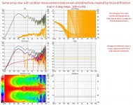
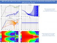
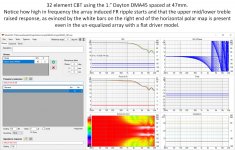
It didn't take long to see that the raised upper mid, lower treble response off axis is a result of equalization to flatten the array effect frequency response ripple. One can see this ripple and the blooming in the horizontal polar map in these CBTs even with no equalization at all.
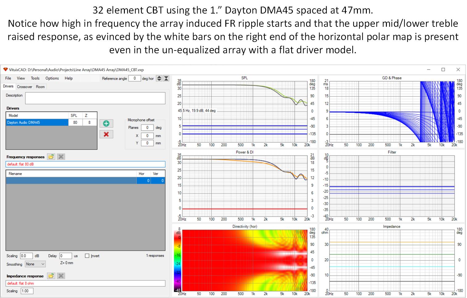
Going to the smaller Dayton DMA45 driver reduces this effect and pushes it higher in frequency and so that is where I'm going to concentrate my efforts.
Going to the smaller Dayton DMA45 driver reduces this effect and pushes it higher in frequency and so that is where I'm going to concentrate my efforts.
Attachments
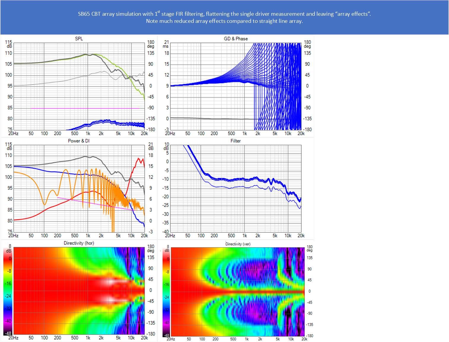
Before going ahead with DMA45, here is the best I was able to do with the SB65 CBT

If I were doing this in the real world instead of simulation, I might never notice that peak in the power response and would think I had done exceptionally well based on the frequency response measurements alone. I would notice a potential problem if I took detailed polars. Listening tests might or might not confirm a problem based on level of room treatment and thus ratio of direct to reflected power and how delayed the reflections are.
In simulation, we can equalize on that direct wave that is so difficult to isolate in the real world but too much of that can be a mistake even if the corrections hold over an adequately wide listening window. In the real world, we can choose to allow more or less of the reflected energy into our equalizer depending on the window used. I guess that is where DRC excels given its sophisticated FDW. But I think that so long as these peaked off axis reflections are delayed enough not to be early reflections, they will be outside any reasonable FDW window.
And far off axis reflections are going to bounce off the near side wall, where presumably one has treatment for early reflections. That might be enough to preclude audibility of this peaked off axis response.
But like fluid says the array in room never responds quite like one would expect...
Attachments
- Home
- Loudspeakers
- Full Range
- Full range line array for wall or corner placement