A box with 60 3” SB10PGC21-4 / Fiberglass – Sbacoustics is on its way to me, and my first project with them will be an open baffle line array. ......
Best regards,
erik
Cool - this will be interesting!!! Do you own a TC-9 by any chance? Would be nice to hear your view on sound difference between these...
//
Pls start a new thread on your build!?
1/4 WL separation rule is the same concept as in synergy mid port placement and as my frequency shading rule: Go past 1/4 wavelength and drivers subtract instead of add, resulting in nulls or combing, or, just frequency response ripple.
But what matters in a line array is not the separation on the baffle so much as the difference in path length from any driver to the mic/ear vs from the central driver to it. Of course more separation on the baffle results in higher delta path length.
The 85 mm TC9 spacing equates to a wavelength of about 4 khz and 4 khz or so is where you will see bad things starting to happen in my simulated vertical polar maps and 8 khz is where you will see combing vs equalizable ripple appear in the frequency responses of a simulated unshaded array. (that is at a listening distance of 3-4m, the further out you go the less the delta path length for a given driver separation. W knows this, there is a copy of his famous diagram back just a few pages)
I asked XDIR what directivity we would get from this 1/4 spacing rule
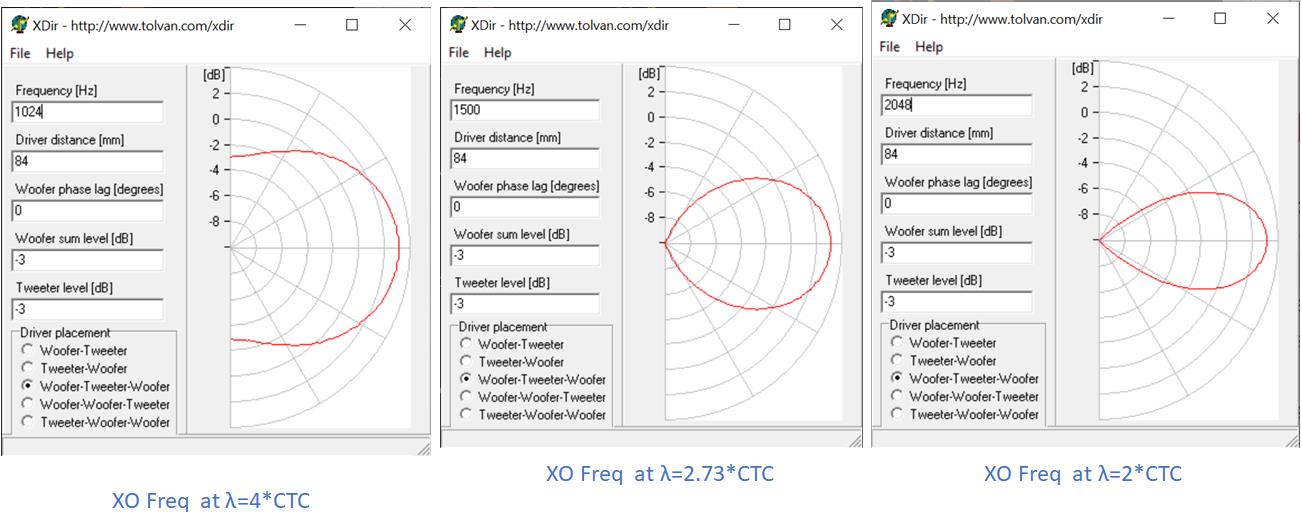
It seems to me that the 1/4 rule gives too wide a vertical beam. Too much energy will be splashed off floor and ceiling and come back to the ear/mic to cause combing.
Using a 1/2 wave rule gives too narrow a beam that will result in something suitable for a single listening height.
At Wesayso's position, there is a 14 degree elevation to standing ear height. The middle diagram will be down < 1 db at that angle. There is still significant energy hitting the floor at 20 degrees but it will return to ear height well past the listener. This seems like a good choice.
The challenge is to maintain this directivity throughout the audible spectrum...
Attachments
1/4 WL separation rule is the same concept as in synergy mid port placement and as my frequency shading rule: Go past 1/4 wavelength and drivers subtract instead of add, resulting in nulls or combing, or, just frequency response ripple.
But what matters in a line array is not the separation on the baffle so much as the difference in path length from any driver to the mic/ear vs from the central driver to it. Of course more separation on the baffle results in higher delta path length.
The 85 mm TC9 spacing equates to a wavelength of about 4 khz and 4 khz or so is where you will see bad things starting to happen in my simulated vertical polar maps and 8 khz is where you will see combing vs equalizable ripple appear in the frequency responses of a simulated unshaded array. (that is at a listening distance of 3-4m, the further out you go the less the delta path length for a given driver separation. W knows this, there is a copy of his famous diagram back just a few pages)
Yep, I totally get the 1/4WL rule is about phase summation, and how the summation arrives at listening position. And yep again, no matter whether synergy, line, or you name it...
My question was more about when does a real world line start to behave like a theoretical infinite line, and not comb at all.
Because i can hear no combing, or probably better said, no variation due to listening height phenomenon on the electrostats for VHF.
A little bit of listening to them yesterday showed me that is really is just for VHF, not HF too like i was remembering. (defining VHF as starting somewhere above 6-7kHz, maybe even higher..)
So I hit the textbooks looking for a rule of thumb as to when a real world line behaves like a theoretical line. (when center to center spacing is sufficiently tight and isn't an issue)
Found an article by Danley that said consensus seems to be when a line is 40-50 wavelengths long.
Which to me means if you had 10ft ceilings, and a floor-to-ceiling ribbon, we might get ideal directivity without combing, and theoretical line behavior, down to around 4500 Hz.
I know floor to ceiling is supposed to extend a line's length via reflections.
Makes me wish i had a room with concrete floor and ceiling....and maybe concrete corner wall sections too... to get strong reflections...
Just thinking out loud...pls pardon if not fully on topic...
lets distinguish continuous line source from infinite length line
its the continuous line source that doesn't comb regardless of how many ceiling and floor reflections contribute to the total SPL, multiplying its effective length. But I would bet that those reflections do mitigate the combing for a discrete line source, filling in the nulls to some extent. Another mitigating factor for combing is that the frequency of onset increases the further away you listen. What remains disappears under ERB and like smoothings that purport to reveal the response that we hear, so I concur it isn't audile except in the very near field.
A discrete line source will always show some combing in source summation analysis like Vituix performs unless frequency shaded like I simulated. Combing actually increases with line length.
Your electrostatics are continuous sources (aren't they? or are they a fine grid?) so they wouldn't comb; they might be too wide to be considered lines.
I'd like to see that Danley article. I think it is effective length that has to do with uniformity vs height but its driver spacing that has to do with combing. At the lower end of the combing scale, where it is just starting to be visible, we see frequency response ripple that we equalize and that ripple may contribute to response variation with height (not sure, need to run a couple sims to check), but anyway, its not clear cut.
What is going on in the VHF is that driver directivity, especially for something as large as the TC9 is doing some frequency shading. The VHF from the most extreme drivers is attenuated at the mic increasingly with frequency as frequency rises.
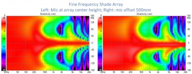
I took a shot at maintaining that beam width across the entire spectrum and almost made. The vertical beamwidth is 10 degrees but in the treble it seems to be limited by the beaming of the central TC9 itself. This is a combing free array at this 3m listening distance, absent the ground image. Other such combing free arrays have been more like 5 degrees vertical beamwidth. This is the flattest directivity index (red trace middle graph) I've seen.
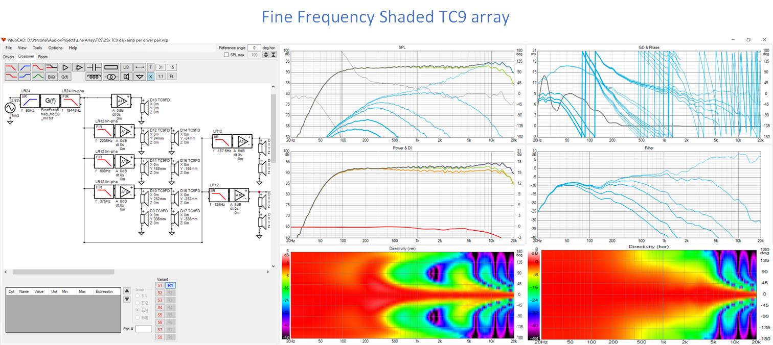
The expansion in this array is not only increasing length with decreasing frequency but also increasing driver group size for groups further away from center. The outermost two groups have 8 drivers each and IIR filters. The other groups have linear phase filters. The filter for the group closest to center is the most critical and absolutely requires IIR or the filter phase shift hurts the directivity. Further out, linear phase becomes less critical. The other linear phase filters could be changed to IIR with smaller injury to directivity some of which could be made up with via DSP delay. Raising the corner frequencies narrows the directivity.
This does require a fair number of amps and DSP channels; a custom DSP/DAC/chip amp board would go a long way towards making it practical for most.
Attachments

There is a thread about a line arrays with a lot (8 or 10) amplifiers per channel and DSP to allow setup as shaded CBT, no shade, and probably everything in between. I can search it tomorrow.
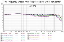
Checked the response vs mic height and it seems too good to be true
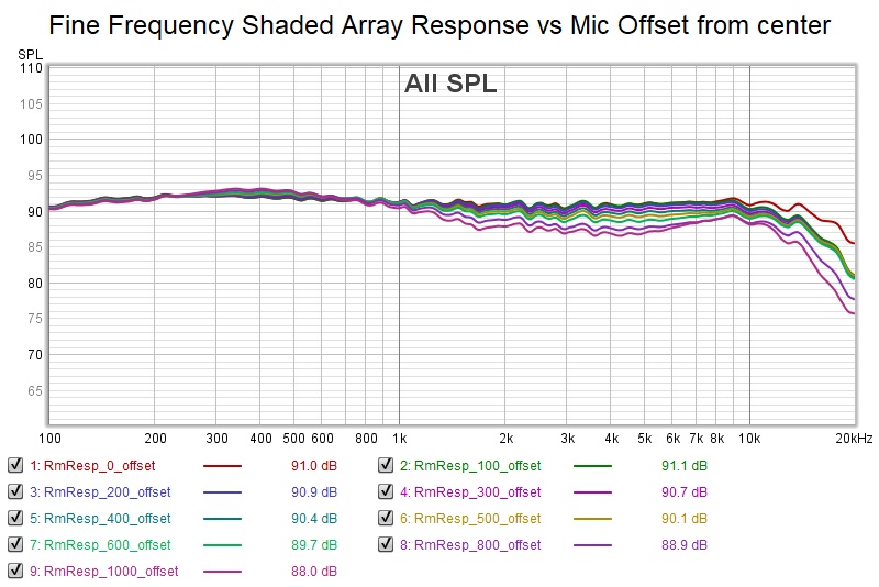
Strangely, if you move your ear up or down relative to array center height, it seemingly widens its vertical directivity to accomodate you or rather, its axis of symmetry moves in the opposite direction. Somehow this helps...
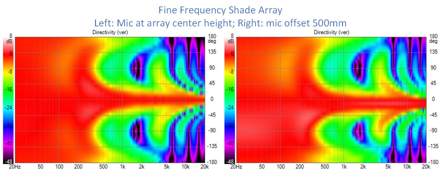
My expectation is that adding ground image drivers won't change this aspect much but we shall see.
Strangely, if you move your ear up or down relative to array center height, it seemingly widens its vertical directivity to accomodate you or rather, its axis of symmetry moves in the opposite direction. Somehow this helps...
My expectation is that adding ground image drivers won't change this aspect much but we shall see.
Attachments
Last edited:
I don’t think resistive shading is a good idea and that is what the plots are showing. For a true expanding array, the response of the outer drivers should roll off. Can you sim 5 driver groups with an inductor to simulate the roll off? By the time you get to the center, the directivity is determined by the tweeter and waveguide combo.
The other, purer, way to improve this topology is to use smaller drivers. Tmyphany has some Good candidates here in the 1 and .75 inch range. Cost is a concern though because you need 100+ drivers for two arrays. But I bet that would push combing above 10 kHz.
The other, purer, way to improve this topology is to use smaller drivers. Tmyphany has some Good candidates here in the 1 and .75 inch range. Cost is a concern though because you need 100+ drivers for two arrays. But I bet that would push combing above 10 kHz.
The last array described in this thread does not use resistor/amplitude shading but frequency shading. This frequency shading eliminates combing on responses coming directly from the driver but not on those longer delayed reflections from floor and ceiling reflections. I have a spreadsheet that calculates the delta path length and corresponding quarter wave frequency for each driver allowing me to set low pass filter cutoff frequencies before the phase shift from any driver reaches 90 degrees.
I've shown resistive shading isn't as good as frequency shading even when paralleling the resistors with inductors to undo the shading at low frequencies. Amplitude shading reduces but doesn't eliminate destructive/subtractive combination from distant drivers. In frequency shading I see a strong advantage for using linear phase filters in frequency shading because of the lack of filter delay. I suspect that this can be worked around to some extent with compensating delays in the center driver channel but haven't seriously tried that yet.
Yes, smaller drivers would help get a wider response and you really just need them in the center. MTMing the center triplet gets some control of the vertical directivity. An unrestrained tweeter has too wide and tall a response. A small waveguide would be ideal but I need directivity files to incorporate one into the sim.
If you want to look at an array of small drivers, consider the Dayton DMA45. Its 1.5" and has a nice response. I've tested one but not listened to it to any degree. My attention though is going to be on this frequency shaded expanding array. The overall response will be better. Its not just the elimination of combing, its more uniform response vs elevation and distance.
Last edited:
A quick word about implementation. Right now it stands at 6 amplifiers per side, with 3 channels needing linear phase filters and IIR/passive sufficing for the rest. My gut tells me that the outermost two groups could be combined without ill effect. I have an 8 channel amp and various 2 channel amps. A 2nd 8 channel amp of the same quality would be almost $2K so I'm not in a hurry to go there.
For standalone DSP, I would look at miniDSP. One $375 OpenDRC-DA8 per side would do the job as well as providing a DAC. There are any number of chip amp boards available from Parts Express or on Ebay. The problem there would be choosing the best. There would be a risk because its not clear what quality of amp is good enough for something like this. I don't think the single ended RCA interconnect would be a problem with DA8 and chip amps in close proximity and good grounding practice.
For standalone DSP, I would look at miniDSP. One $375 OpenDRC-DA8 per side would do the job as well as providing a DAC. There are any number of chip amp boards available from Parts Express or on Ebay. The problem there would be choosing the best. There would be a risk because its not clear what quality of amp is good enough for something like this. I don't think the single ended RCA interconnect would be a problem with DA8 and chip amps in close proximity and good grounding practice.
Cool - this will be interesting!!! Do you own a TC-9 by any chance? Would be nice to hear your view on sound difference between these...
//
Pls start a new thread on your build!?
No, I do not own a TC-9 line array, I have never actually heard one.
I will start my own thread indeed. I have some different ideas about integrating them in the living room, and curious if and how they will work out.
The thread has become quite long, so I may have missed it. Have you simulated some "capacitive shading", like applied in this project?
Bauanleitung | Visaton
I reckon it is only 6dB/octave, but probably much simpler.
Bauanleitung | Visaton
I reckon it is only 6dB/octave, but probably much simpler.
I don’t think resistive shading is a good idea and that is what the plots are showing. For a true expanding array, the response of the outer drivers should roll off. Can you sim 5 driver groups with an inductor to simulate the roll off? By the time you get to the center, the directivity is determined by the tweeter and waveguide combo.
The other, purer, way to improve this topology is to use smaller drivers. Tmyphany has some Good candidates here in the 1 and .75 inch range. Cost is a concern though because you need 100+ drivers for two arrays. But I bet that would push combing above 10 kHz.
And here I cant help start thinking about a ribbon /planar...
//
lets distinguish continuous line source from infinite length line
its the continuous line source that doesn't comb regardless of how many ceiling and floor reflections contribute to the total SPL, multiplying its effective length. But I would bet that those reflections do mitigate the combing for a discrete line source, filling in the nulls to some extent. Another mitigating factor for combing is that the frequency of onset increases the further away you listen. What remains disappears under ERB and like smoothings that purport to reveal the response that we hear, so I concur it isn't audile except in the very near field.
A discrete line source will always show some combing in source summation analysis like Vituix performs unless frequency shaded like I simulated. Combing actually increases with line length.
Your electrostatics are continuous sources (aren't they? or are they a fine grid?) so they wouldn't comb; they might be too wide to be considered lines.
I'd like to see that Danley article. I think it is effective length that has to do with uniformity vs height but its driver spacing that has to do with combing. At the lower end of the combing scale, where it is just starting to be visible, we see frequency response ripple that we equalize and that ripple may contribute to response variation with height (not sure, need to run a couple sims to check), but anyway, its not clear cut.
What is going on in the VHF is that driver directivity, especially for something as large as the TC9 is doing some frequency shading. The VHF from the most extreme drivers is attenuated at the mic increasingly with frequency as frequency rises.
Good stuff...thx.
Continuous line vs line length....
I take continuous line to mean that 1/4WL or less, center-to-center spacing, exists for all frequencies up to and including highest frequency of interest.
Which for 20kHz would require c-to-c spacing of about 4mm, or impossible for anything other than ribbons, planars, or maybe a crazy long AMT.
I take length as the length of the continuous line.
Those definitions what you had in mind? Seems so...
The Danley reference about a line reaching at about 40-50 wavelengths, what he terms sufficiently long enough to achieve "acoustic infinity", comes from "Handbook for Sound Engineers" Fifth Edition, edited by Ballou.
Tom and Doug Self authored a 30 page chapter on speakers covering a number of topics. He also briefly discusses tapered arrays using frequency shading, saying the goal should be an invariant ratio between the effective length of the array and the wavelength's produced by the shaded elements.
Book has a second chapter on speakers by Ralph Heinz...mostly about arraying, lines, steering, etc. Looks well written, he's super respected in the proaudio install world.... I need to read it 😀
One pair of my electrostats uses continuous vertical wires for the grid, the other uses a perforated plate.
I consider them line arrays only in the vertical sense. Because the one that uses vertical wires has three flat panels splayed a bit, each about 9" wide. And the other has a curved frontal width.
It really is dramatic though, how VHF just disappears on both, once ear is above the top of them.
Back of few pages I showed results using a Dayton PTmini planar tweeter coaxial with a line of TC9s acting as mid-bass up to 4900 Hz. It worked well but did show combing at HF. Shading reduced/eliminated that combing but narrowed the vertical window. I don't believe I tried frequeny shading with it, just amplitude shading. To my mind, the PTmini has too wide a response for my small room.
I have also tried passive/IIR filter shading and the results were not encouraging. The slow roll off and the group delay are problematic. The shading I just showed is by far the best and to me at least, with miniDSP and chip amps not cost prohibitive.
On top of that though, I more than half believe that what combing exists at 3m or longer listening distance isn't audible. Except for the purist, it may not be worth fixing. Except looking deeper, there are other benefits to shading. But I am a purist 🙂 at least in simulation where it isn't expensive.
(sorry, back on my pulpit)
Combing results from destructive/subtractive combining of delayed responses from the more distant drivers relative to the central driver. Shading, as I'm doing it, eliminates that destructive combining, except what might result from HF floor and ceiling reflections if no absorption on these surfaces. Not only is combing eliminated but so too are the frequency response ripple at lower frequencies and the loss of vertical directivity seen in unshaded arrays at higher frequencies. This latest implementation showed a higher degree of response uniformity with height and distance than I've seen or hoped for which wasn't the case in prior models that used fewer amps and DSP channels. These are significant benefits independent of whether or not the combing at HF is audible.
What I meant is the effective line length. Say you have a 2m tall line. If its on a perfectly reflective floor ( a ground plane). The ground reflection, which I model with a set of mirror image drivers, doubles its effective length to 4m. Then there is also the ceiling reflection. With that added to the ground image, the effective length is tripled. Consider what happens with true sound mirrors for floor and ceiling: even the reflections have reflections. That is how one gets to the infinite length model. But you can't get there because of imperfect reflection and driver directivity. Its really hard to know what the effective length of an array in a particular room is; its usually going to be long enough that vertical directivity extends low enough to eliminate floor and ceiling bounce nulls but not long enough that response is invariant vs height. Its best to have a thin layer of absorber on floor (carpet) and ceiling (ceiling tile) to absorb instead of reflect starting at several khz.Good stuff...thx.
Continuous line vs line length....
I take continuous line to mean that 1/4WL or less, center-to-center spacing, exists for all frequencies up to and including highest frequency of interest.
Which for 20kHz would require c-to-c spacing of about 4mm, or impossible for anything other than ribbons, planars, or maybe a crazy long AMT.
I take length as the length of the continuous line.
.
By continuous line I meant exactly that, what you get from a ribbon or planar. A discrete line approximates a continuous line, at least at LF and MF. That approximation begins to break down at 1/4 wave spacing and is completely gone by 2 wavelength spacing.
The reason I drew the distinction was to emphasize that the effects of being finite instead of infinite are different than the effects of being discrete vs continuous.
Thanks for reference to the book. I will have to get a copy
I think your point above about how good an amp is "good enough" is valid. This becomes a difficult and potentially expensive experiment to find out that the one you chose was not good enough.
The differences between amps and DAC's to me are not night and day when they are well designed but the differences are there and those differences don't seem to be replicated in EQ and can ultimately be a bottleneck in the system.
Multi channel active seems like such a no brainer until you try and do it 🙂
I find myself these days looking for systems that cut down the number of active channels required at least in the main speakers. I am sorely tempted to try the purifi amp to see if that is good enough.
One thing I have wondered in these sims is does vituix predict the frequency dependent gain that you get with a floor to ceiling line. The same shape appears in all real measurements but I haven't noticed it in your graphs. Did you EQ it away or was it not there to begin with? Or did I just not see it.
- Home
- Loudspeakers
- Full Range
- Full range line array for wall or corner placement