Trying to adjust to the new Virtuixcad, I can't quite understand the driver offset. As all drivers move up or down, but my ceiling and floor stay put.
Wouldn't it have been easier if the mic just moved up or down?
The problem was the mic height could not be changed with floor and ceiling reflections on. Now it just complicated my work, having to move 3 parameters for one little change, what do I not get here?
Wouldn't it have been easier if the mic just moved up or down?
The problem was the mic height could not be changed with floor and ceiling reflections on. Now it just complicated my work, having to move 3 parameters for one little change, what do I not get here?
I made many more simulations today. Overall it turned out to be quite hard to improve upon an unshaded array, once the ceiling reflection was added as well.
I may have found an improvement though, but it is less than I first anticipated. I'm going to try a little harder, but breaking up the symmetry kills the standing listening position. Even though I did sim my non true floor to ceiling, as it falls a little short in height.
I may have found an improvement though, but it is less than I first anticipated. I'm going to try a little harder, but breaking up the symmetry kills the standing listening position. Even though I did sim my non true floor to ceiling, as it falls a little short in height.
Last edited:
Trying to adjust to the new Virtuixcad, I can't quite understand the driver offset. As all drivers move up or down, but my ceiling and floor stay put.
Wouldn't it have been easier if the mic just moved up or down?
The problem was the mic height could not be changed with floor and ceiling reflections on. Now it just complicated my work, having to move 3 parameters for one little change, what do I not get here?
It was a quick fix for Kimmosto, who are we to complain?
Today I addressed my concern for the SPL capability of the expanding array. Concerns about the single center driver handling multiple octaves alone had been addressed by changing to the very robust SB26 tweeter in a waveguide. I didn't voice my concern but I was certainly aware that that left the pair of TC9's flanking the tweeter working alone on the 3 khz to 6 khz octave.
The Vituix enclosure tool has a checkbox in its lower left corner that allows you to focus on a single driver in the crossover schematic and see its excursion and power curves. Focussing on one of the tweeter flanking TC9s, I found that I had to reduce the axial SPL to 93 db to keep its power consumption below 30W. That is not good enough. For this to be a viable design, I would have to find a more robust device to flank the tweeter. No doubt such devices exist but I don't feel like looking for one. For the moment at least, I'm content with having uncovered not so much the Achilles heel of expanding arrays but their fundamental difference with a line array. In the line array, all drivers are the same. The expanding array is optimized when the characteristics of each driver are selected based on their position in the array.
So I wll go back and join Wesayso in assessing whether shading is beneficial for (almost) floor to ceiling arrays and trying to ultize new features in Vituix to improve array simulation accuracy.
Taking a look at the responses with and without floor and ceiling reflections enabled.
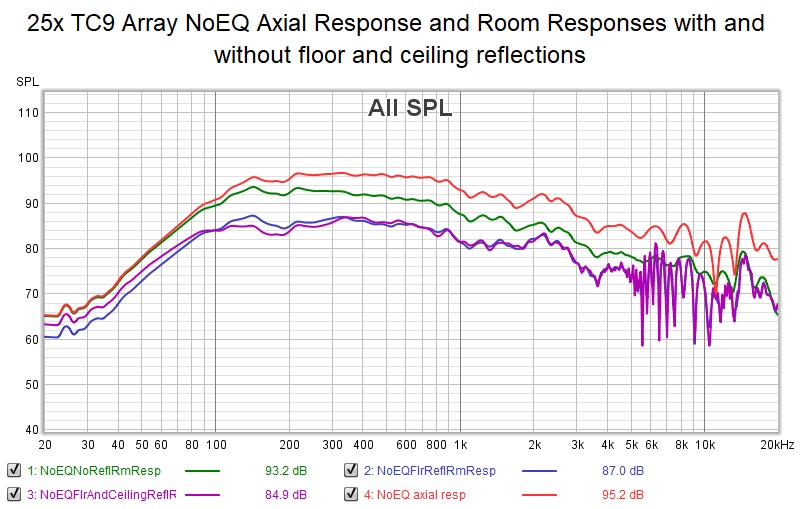
Did anyone ever wonder why the level of the room response curve drops when these reflections are enabled? I've been puzzling over this for a while and I finally realized its because the reflections are delayed long enough to combine subtractively. Fortunately I already have the delta path lengths for the floor image in a spreadsheet
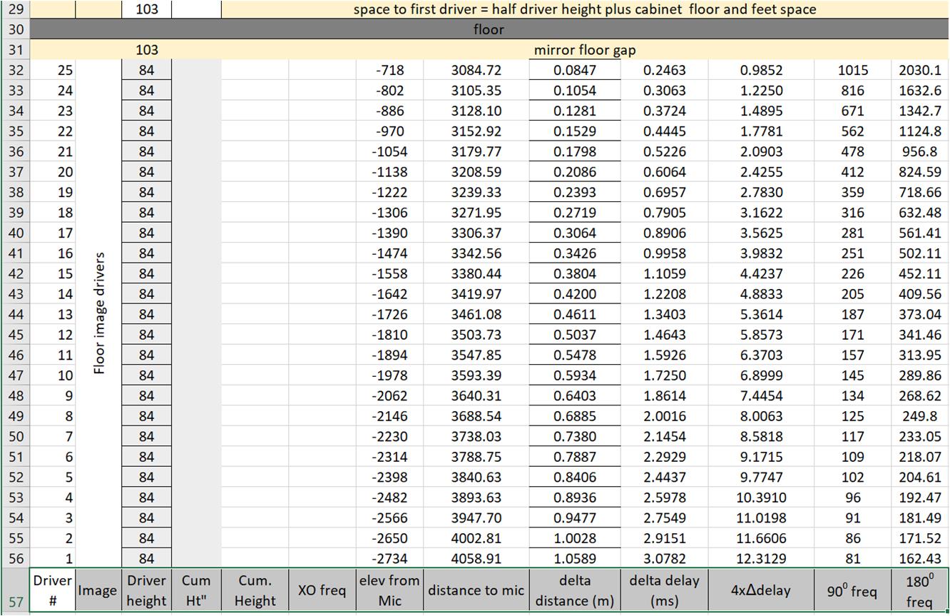
below 500 hz all but the bottom 4 drivers combine subtractively below 500 Hz. By symmetry, if it were precisely symmetrical, then all but the top 4 drivers would combine subtractively in the ceiling reflection summation.
That is an interesting thing to understand. When I first saw this, I thought it might be a Vituix anomaly but its not, its real. You might never notice it though without simulation unless you compared indoor and outdoor measurements.
The other prominent effect is the increased combing amplitude and frequency above 5 khz. This is why I've been recommending a thin layer of floor and ceiling absorption.
Did anyone ever wonder why the level of the room response curve drops when these reflections are enabled? I've been puzzling over this for a while and I finally realized its because the reflections are delayed long enough to combine subtractively. Fortunately I already have the delta path lengths for the floor image in a spreadsheet
below 500 hz all but the bottom 4 drivers combine subtractively below 500 Hz. By symmetry, if it were precisely symmetrical, then all but the top 4 drivers would combine subtractively in the ceiling reflection summation.
That is an interesting thing to understand. When I first saw this, I thought it might be a Vituix anomaly but its not, its real. You might never notice it though without simulation unless you compared indoor and outdoor measurements.
The other prominent effect is the increased combing amplitude and frequency above 5 khz. This is why I've been recommending a thin layer of floor and ceiling absorption.
Attachments

I'm looking for simple solutions, that produce a better overall result. This one was quite effective despite floor and ceiling reflections:
A clear reduction in reflections, same properties were set for floor and ceiling.
As I do want to keep a good standing result the optimisation is limited. However it does make a clear difference and it makes a standing result at 4m (and further) distance even better than it is right now.
The schematic:
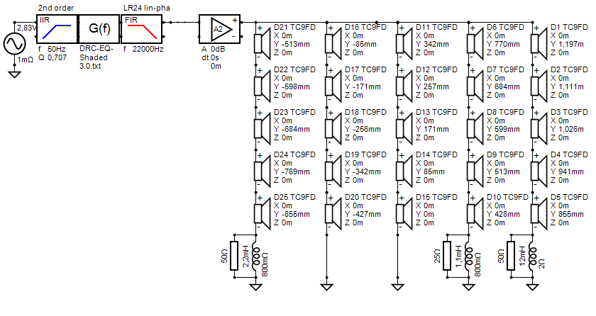
This is something I could go for. But hey, maybe we can whip up better results. All properties are a match to my room/my arrays. Except that I don't know how much floor and ceiling reduce their reflections. Treatment there is no option for me. That's why I went with these arrays in the first place 😀.
Did you try adding the back wall? It does match my room results pretty good.
Can we export the in room orange curves (middle graph) somehow? That's the actual one that is used as a base for processing in my reality 😉.
Never mind, yes we can. Found them under export. Sadly no IR export, just a txt file. Do I remember there being a tool inside this program than can
create the impulse? I'll find it 🙂.
A clear reduction in reflections, same properties were set for floor and ceiling.
As I do want to keep a good standing result the optimisation is limited. However it does make a clear difference and it makes a standing result at 4m (and further) distance even better than it is right now.
The schematic:
This is something I could go for. But hey, maybe we can whip up better results. All properties are a match to my room/my arrays. Except that I don't know how much floor and ceiling reduce their reflections. Treatment there is no option for me. That's why I went with these arrays in the first place 😀.
Did you try adding the back wall? It does match my room results pretty good.
Can we export the in room orange curves (middle graph) somehow? That's the actual one that is used as a base for processing in my reality 😉.
Never mind, yes we can. Found them under export. Sadly no IR export, just a txt file. Do I remember there being a tool inside this program than can
create the impulse? I'll find it 🙂.
Attachments
Last edited:
I have tried a sort of expanding array too, but I wouldn't even want to go there.
No standing result was acceptable plus we'd lose too much top end capacity.
(I crossed the outer 2 drivers of each unshaded group of 5 with a capacitor. It did raise the volume.
Sadly I couldn't find a mix where there was a good compromise for standing/sitting listening positions.
In that case I would rather build something looking much like the Dunlavy speakers 🙂.
Last edited:
......
For the moment at least, I'm content with having uncovered not so much the Achilles heel of expanding arrays but their fundamental difference with a line array. In the line array, all drivers are the same. The expanding array is optimized when the characteristics of each driver are selected based on their position in the array.
.....
I came to the conclusion that an expanding array is basically just a WMTMW.
(provided the definition of expanded array means different sized drivers are used.)
In that case I would rather build something looking much like the Dunlavy speakers 🙂.
Yes, that is where expanding array leads. Snell, KEF and the JBLs that H-K developed the H-k XO for, as well.
I'm glad you got me on this sim mission, nc535! With it, I can explain so much more of what I've encountered. It also holds the answer why I have the toe-in set like I did. It's pretty revealing of some of the things that I've wondered about. Great stuff! And I'm only on my 3rd day of simming 🙂.
I only guessed at my off angles so far, I'll measure what I really have and go from there. Fun to be able to see this in sims.
With a bit of practise I guess we can get pretty far to extract a good DSP recipe from it too.
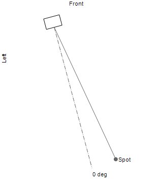
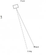
My guesses were right, arrays turned in 15 degree. Measurement position is at a 10 degree angle.
I only guessed at my off angles so far, I'll measure what I really have and go from there. Fun to be able to see this in sims.
With a bit of practise I guess we can get pretty far to extract a good DSP recipe from it too.
My guesses were right, arrays turned in 15 degree. Measurement position is at a 10 degree angle.
Attachments

Last edited:
Taking a look at the responses with and without floor and ceiling reflections enabled.
One more line for yesterday's graph - 50 drivers with floor and ceiling reflections.
I wanted to see if the response reaches a limit as more drivers and reflections are added. Then I will know we are modelling enough drivers, or at least there is no point to adding more.
From this picture we are just about there - the 50 driver trace lowered 3 db aligns nicely with the 25 driver trace in the midbass and has the same character, so to speak, up higher.
Attachments
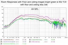
Here's a comparison at the listening spot for a frequency shelf-shaded array vs unshaded:
The upper results are the shelf-shaded array, bottom is the unshaded array.
These are the in-room results of positions between -100 to +100mm around the 1000 mm height measurement spot. I'd say it looks to be worth the trouble. The results of the 15 degree array toe-in and 10 degree off axis listening is much more in line with what I had expected.
The results are more even than the prior angle I used (on axis sims). Pretty much in line with my toe-in experience a long long time ago. The 10 degree off axis was my subjectively preferred listening angle, having the array cross behind the listening spot. (or in front but due to how strange that looked I did not dare let that pass judgement on the WAF front)
Edit: these simulations keep a reasonable tonal balance up to 1700 mm. That's the rule number one: it should work standing up.
A by-product of the shaded array is much better tonal performance standing up and at 4 m distance. So room sound could improve too.
Attachments

Last edited:
I wanted to see if the response reaches a limit as more drivers and reflections are added. Then I will know we are modelling enough drivers, or at least there is no point to adding more.
From this picture we are just about there - the 50 driver trace lowered 3 db aligns nicely with the 25 driver trace in the midbass and has the same character, so to speak, up higher.
So you're still building your own floor reflections? Now that I can vary the microphone height, I've just been using the floor and ceiling options within Virtuix. It has a limit with one value for reflections of both ceiling and floor, but it is useful enough to see trends.
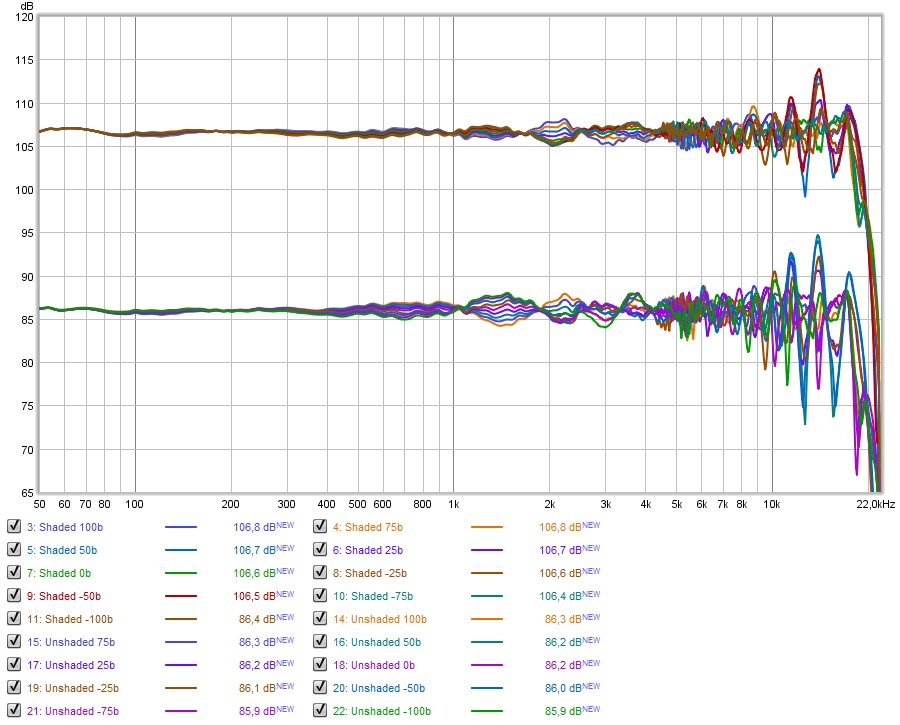
Belonging to the above graph, comparing shaded vs unshaded the 6-pack from Virtuixcad:
The in-room results were averaged and used for EQ correction in both plots.
So to recap:
I applied a pré-eq to get a somewhat flat result. Next I exported the Listen win SPL, which I altered in value to see a window of +/- 15 degree horizontal and +/- 5 degree vertical.
The listen-win IR was then corrected by DRC-FIR. The result of that was convolved with the pré-EQ to get a total correction.
This total correction was applied within Virtuixcad to the sim. Next I exported the in-room results looking at the height-differences from -100, -75, -50, -25, 0, 25, 50, 75 up to 100.
These results were averaged (non vector) and I let REW do auto EQ on that result, with a few quick tweaks. That EQ was applied to all measurements and the correction as seen in the upper six-pack(s).
Same procedure for both sims, Shaded and Unshaded.
Lots of work, but I need to find out if operating on the arrays is worth the trouble.
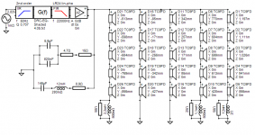
In the shaded version I've included my impedance correction schematic.
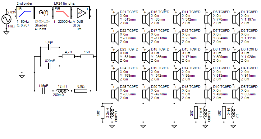
It is what I run, so I included it in the sim.
The above is with the earlier mentioned toe-in:

The in-room results were averaged and used for EQ correction in both plots.
So to recap:
I applied a pré-eq to get a somewhat flat result. Next I exported the Listen win SPL, which I altered in value to see a window of +/- 15 degree horizontal and +/- 5 degree vertical.
The listen-win IR was then corrected by DRC-FIR. The result of that was convolved with the pré-EQ to get a total correction.
This total correction was applied within Virtuixcad to the sim. Next I exported the in-room results looking at the height-differences from -100, -75, -50, -25, 0, 25, 50, 75 up to 100.
These results were averaged (non vector) and I let REW do auto EQ on that result, with a few quick tweaks. That EQ was applied to all measurements and the correction as seen in the upper six-pack(s).
Same procedure for both sims, Shaded and Unshaded.
Lots of work, but I need to find out if operating on the arrays is worth the trouble.
In the shaded version I've included my impedance correction schematic.
It is what I run, so I included it in the sim.
The above is with the earlier mentioned toe-in:
Attachments
It looks like a performance upgrade worth the trouble. A nice reduction of peak values in the upper end, plus better performance overall.
I simmed way more than this to be honest, been at it like crazy. Trying to find improvement in the top end but I couldn't nail it entirely.
An almost 30% wobble reduction should do nicely though 😀.
I simmed way more than this to be honest, been at it like crazy. Trying to find improvement in the top end but I couldn't nail it entirely.
An almost 30% wobble reduction should do nicely though 😀.
- Home
- Loudspeakers
- Full Range
- Full range line array for wall or corner placement