You'll need to determine what you will do with the specific side wall reflections, floor and ceiling, then.Farfiled I took as 1m. My baffle is "infinite" as built in flush with wall. Gated to deal ? with room effects
With delay adjusted, straight except where the response rolls off or changes.OK understand. How should it look if phase is good?
This will wrap it again.. You could just leave it, or if you want to put that processing to work, you could adjust phase, not delay.So do you delay the high output? 360 degrees = how many secs?
Also says:
"The main advantage of LR filters is, when usind them as low-pass and high-pass crossover filters (with the same cut-off frequency) your total filter response will be flat."
That's what i said. Additionaly, the phase rotation of the drivers matches to each other, because LR slopes are created to be in-phase.
So all you need is to create LR(4) responses from the driver responses. The easiest way with DSP is to flatten the driver responses before apply the xo filters.
Please show the flattened responses without xo filters or show the xo filtered responses with target response overlay.
Delay is for compensate the different acoustical center distances at the desired axis.
The phase from each section will move away in opposite directions.Additionaly, the phase rotation of the drivers matches to each other, because LR slopes are created to be in-phase.
Hi Alan,
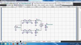
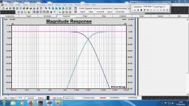
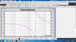
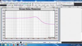
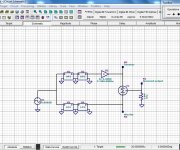
Please see attached sim of LR4 crossover. Note that all three phase resonses and group delay responses from LPF, HPF and Summed output, overlap each other.
Since the group delay and phase response of the summed output are not flat, but the summed output magnitude is, the response is therefore not minimum phase.
Peter
Attachments
Last edited:
Hi Peter,
Thanks for the simulatuion, it's very useful to see what's happenening.
Can you please delay the high-passed driver's response with one cycle (360 degree, 1/2000=0.5 ms or 500 us) like Steve asked?
If all is true, then we'll see why crossover delay compensation doesn't work that way.
Thanks for the simulatuion, it's very useful to see what's happenening.
Can you please delay the high-passed driver's response with one cycle (360 degree, 1/2000=0.5 ms or 500 us) like Steve asked?
If all is true, then we'll see why crossover delay compensation doesn't work that way.
Last edited:
Hi Denibeni
You said flatten to one octave beyond cutoff freq. So I suppose a lot of Boost/Cuts? To what precision? +/- 1dB or +/- 0.1dB? Manufacturers curve pretty flat. My measured curves, not flat.
You said flatten to one octave beyond cutoff freq. So I suppose a lot of Boost/Cuts? To what precision? +/- 1dB or +/- 0.1dB? Manufacturers curve pretty flat. My measured curves, not flat.
Hi Denibeni
You said flatten to one octave beyond cutoff freq. So I suppose a lot of Boost/Cuts? To what precision? +/- 1dB or +/- 0.1dB? Manufacturers curve pretty flat. My measured curves, not flat.
Hi!
In my opinion, +/- 1dB is usually enough. But with the flat response and good phase tracking we just try to create a starting point. Flat on-axis response does not guarantee a good sound even if the phase tracking is good.
Thank you PLB. It's good to have someone watching me. I'm not on the crossover phase of my latest build cycle but I'm trying to keep up. I could use some re-training 😱Hi Alan,
Please see attached sim of LR4 crossover.
Hi Denibeni,
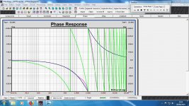
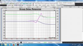
Here are the sims with a 500uS delay added to the HP section. I think these results clearly show that the phase tracking between the HP and LP through the crossover region is completely chaotic, resulting in the magnitude and group delay response irregularities through this region as shown. What this does highlight though is the need to compensate for the difference in acoustic centers between the various drivers.
Hope this helps.
Peter
Attachments

Thanks Peter!
That's what I thought. As we can see, the phases are overlaps only at 2kHz, anywhere else the condition is chaotic.
This is why the delay is only used to compensate for acoustic center distances with symmetrical slopes or to provide minimal correction when the crossover curves are asymmetric and the phases do not overlaps at xo frequency.
Thanks Denibeni, Peter, Charlie, Allen, Draki and Juhazi.
Now I'm more confused. Is there a book where I can learn all this and not have to ask so many questions?
If for example the 4thOrder LR XO results in 360degree phase shift, one period delay in low output, I would have thought that delaying the high output would eliminate the shift???? Obviously not from Peter's simulations. What have I missed?
And if nothing is done about the 360 shift, is it audible?
Thanks Denibeni, Peter, Charlie, Allen, Draki and Juhazi.
Now I'm more confused. Is there a book where I can learn all this and not have to ask so many questions?
If for example the 4thOrder LR XO results in 360degree phase shift, one period delay in low output, I would have thought that delaying the high output would eliminate the shift???? Obviously not from Peter's simulations. What have I missed?
And if nothing is done about the 360 shift, is it audible?
You can't eliminate the 360 degree phase shift but you can't hear it either, so don't worry.
Peter's simulations shows what happens in the real world, i tried with my speakers.
Concentrate on to get LR4 responses now.
Thx, this fixed thread will help you a lot
So you want to design your own speaker from scratch!
No, crossovers done right are transparent, you can't hear that phase shift. There is controversy about different xo topologies sounding different with music, but it is mostly about how well they have been implemented in each speaker contruction and specific drivers.
Thx, this fixed thread will help you a lot
So you want to design your own speaker from scratch!
No, crossovers done right are transparent, you can't hear that phase shift. There is controversy about different xo topologies sounding different with music, but it is mostly about how well they have been implemented in each speaker contruction and specific drivers.
Yeah this, and i think the main audibility reason for different topologies is the different power responses and how well the driver nastyness been filtered out.
Last edited:
Ok, what?The main reason is that few people do their crossovers in three dimensions.

Is there a book where I can learn all this and not have to ask so many questions?
https://www.amazon.com/Loudspeaker-Design-Cookbook-Vance-Dickason/dp/1882580109
https://www.amazon.com/High-Performance-Loudspeakers-Martin-Colloms/dp/0470094303
https://www.amazon.com/Introduction-Loudspeaker-Design-John-Murphy/dp/0966377346
et al...
Thanks for that. I'll give a go. It's the "electronics" I have most trouble with. The acoustics I understand. For example it's only recently that DeniBeni has convinced me to flatten the individual useable freq of each driver first. I suppose for phase reasons, whereas I thought that I apply XOs first in order to deal (equalise) less freqs as most would be "cut out" of the processing by the high and low passes. Awful lot of boost/cuts to use to flatten
Hi Steve!
Yes, we flatten it for phase and frequency response to make sure that the lowpass and highpass match as well as possible. We flatten it out because we can do it with DSP, as someone has said before. Of course, there is no need to follow this path, as all this has its advantages and disadvantages. A DSP crossover can be done similarly (but not exactly) as a passive crossover.
A passive crossover is made quite differently. There you have to take into account the specific driver curves (both frequency and impedance), simulating passive components into the circuit and observing what comes out, then adjusting and then trying out new components and topologies until you get what you want or what the curves dictate (broadly speaking).
That's why in many cases, with an electrically 2nd order passive crossover, you can achieve, for example, a 4th order acoustic curve because you combine the driver curves with the crossover curves.
If you want to do it this way, there will surely be someone who explains how to do it or is just reading it.
One of the great advantages of a DSP crossover is that the speaker driver dictates less about topologies and crossover points. Because if you have a straight "curve" as a frequency response, from this point on you can try almost any crossover filtering very easily and the impedance response can be almost ignored.
With DSP, both methods (combining or flattening) are pretty much the same task, but the flattening method has more potential for experiment IMHO.
- Home
- Loudspeakers
- Multi-Way
- Freq measurements and Hypex Filter Design adjustments